| PLEASE NOTE: The images presented on this page are of low resolution and, as a result, will not print out very well. If you wish to have higher resolution files then you may purchase them for only $2.95 per patent by using the "Buy Now" button below. All purchases are via PayPal. These files have all been cleaned up and digitally enhanced and are therefore suitable for printing, publication or framing. Each zip package contains all the images below (some packages may contain more), and purchased files can be downloaded immediately. |
UNITED STATES PATENT OFFICE.
_________________
BENJAMIN F. BEE, OF HARWICH, MASSACHUSETTS.
PLANE FOR FINISHING GROOVES IN PATTERNS &c.
_________________
Specification of Letters Patent No. 8,503, dated November 11, 1851.
_________________
To all whom it may concern:
Be it known that I, BENJAMIN F. BEE, of Harwich, in the county of Barnstable, in the State of Massachusetts, have invented a new and Improved Mode of Confining and Adjusting the Irons of Carpenters’ Planes and Molding Tools; and I do hereby declare that the following is an exact description thereof, reference being had to the accompanying drawings, and to the letters of reference marked thereon.
The nature of my invention consists in introducing upon each side, in the throat of carpenters planes — (in molding tools in the center of throat) a metallic plate movable perpendicularly to the plane of the iron or cap: the two plates being connected by a metallic bar on which pressure may be produced by a lever, containing an adjusting screw acting upon the principle of the cam, by which screw the pressure upon the iron may be increased or diminished :– the foregoing apparatus to be used in connection with a set screw placed at the back of the iron, the head of the screw working in a slot near the top of the iron by which the iron may be adjusted with ease and delicacy, and retained in its position after adjustment.
To enable others skilled in the art to make and use my invention, I will proceed to describe its construction and operation:
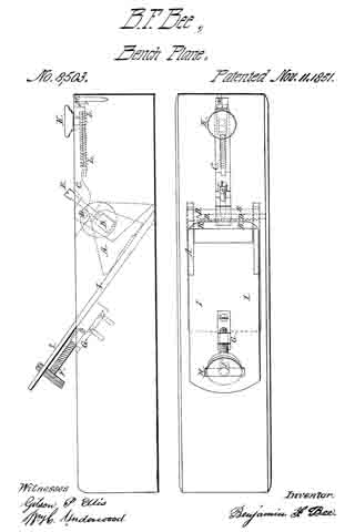
I construct my plane in any of the known forms, with the exception of removing from the throat, that portion of wood usually left for obtaining the action of the wedge upon the iron. I introduce on each side of the throat, into grooves adapted to the purpose, a metallic plate as shown at A, in the accompanying drawings. These plates are perforated near the upper edge by a rectangular hole, through which by means of an oblong mortise leading from the side of the plane stock, I place a metallic bar B, of such length as to reach to the outside of each plate, and of such strength as to sustain the amount of pressure necessary, to confine the iron firmly to the stock. This pressure I produce by the lever C, turning upon the pin D, as a fulcrum, containing the set screw E, acting on the principle of the cam; by which the pressure may be graduated at the will of the operator, according to the circumstances of the several parts.
In molding tools but one of these plates are necessary, the screw E, acting directly upon the upper edge of the plate A. When the rectangular bar B, and the pin D, have been put in their respective places they are retained there, and kept from exposure by a metallic plate, or disk, secured to the stock by screws or otherwise.
In connection with the aforesaid apparatus, I use the set screw F, working in the nut G, placed at the back of the iron; the head of this screw being of such size and shape, as to project through a slot H, near the upper end of the iron, by means of which the iron I may be adjusted to any degree of rankness, and retained in its position after such adjustment.
Whenever the operator would remove the iron from the stock, for the purpose of sharpening, clearing, or whatever else; he places his thumb upon the knob K, by drawing which toward the fulcrum of the lever, the sliding catch L, is released from the dog M; the iron is then liable to be withdrawn, by raising the upper end, so as to clear it of the set screw F. The iron may be returned to its place by a counter process, and confined there by pressing upon the knob K, in such a manner, as to force the catch L, under the dog M; retaining the same degree of rankness as before removal, abating whatever may have been whetted or ground away, and susceptible of any subsequent adjustment by means of the set screw F.
What I claim as my invention, and derise to secure by Letters Patent; is —
The application to carpenters’ planes, and molding tools, of a new method of confining the iron, by a metallic apparatus, acting upon the principles of the lever and cam; in combination with the set screw for adjusting the same, as herein described; using for the purpose, the aforesaid contrivance or arrangement of parts, or any other substantially the same, and which will produce the same effects in like manner.
BENJAMIN F. BEE.
Witnesses:
WM. H. UNDERWOOD,
STEPHEN C. ELLIS.


