
| PLEASE NOTE: The images presented on this page are of low resolution and, as a result, will not print out very well. If you wish to have higher resolution files then you may purchase them for only $2.95 per patent by using the "Buy Now" button below. All purchases are via PayPal. These files have all been cleaned up and digitally enhanced and are therefore suitable for printing, publication or framing. Each zip package contains all the images below (some packages may contain more), and purchased files can be downloaded immediately. |

United States Patent Office.
WILLIAM DUTTON, OF BOSTON, MASSACHUSETTS.
Letters Patent No. 86,741, dated February 9, 1869.
_________________
IMPROVEMENT IN BOX-SCRAPER.
_________________
The Schedule referred to in these Letters Patent and making part of the same.
_________________
To all whom it may concern:
Be it known that I, WILLIAM DUTTON, of Boston, in the county of Suffolk, and State of Massachusetts, have invented a new and useful Irnprovernent in Combined Planer and Scraper; and I do hereby declare that the following is a full, clear, and exact description thereof, which will enable those skilled in the art to make and use the same, reference being had to the accompanying drawings, forming part of this specification.
This invention relates to a new and useful improvement in tools used for scraping and planing boxes or barrels, and for removing the marks therefrom; and the invention consists in attaching to a single stock or handle an adjustable scraper, and an adjustable “planing-iron,” as will be hereinafter more fully described.
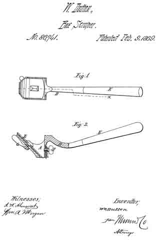
Figure 1 represents a top view of the tool.
Figure 2 is a longitudinal side view, (in section through the line x x,) so as to show the position and method of fastening and adjusting the scraper and planer-“bits.”
Similar letters of reference indicate corresponding parts.
A is a metallic stock, or shell, so formed that a planing-iron, or bit, is confined to it at about the same angle it would occupy in a joiner’s plane.
B represents the iron, or “bit,” of the plane.
C is the scraper.
D is the shank, to which a handle, of wood or other material, may be attached, or the shank may be extended, so as to form a handle itself.
E is the handle.
Both of the bits, B and C, have slot-holes, so that they can be adjusted or set, for properly operating on the wood.
They are fastened by the thumb-screw F and the screw-lever G, as seen in the drawing.
The manner of operating with the tool will be readily understood from the drawing.
I claim as new, and desire to secure by Letters Patent —
The stock A, adapted to receive the adjustable bits B C, all the parts being constructed and arranged as described, for the purpose specified.
WM. DUTTON.
Witnesses:
ALBERT O. NORTON,
MARTHA A. NORTON.