No. 5,620 – Joiner’s Plane (William A. Cole) (1848)

[paiddownloads id=”22″]5620


UNITED STATES PATENT OFFICE.

_________________

WILLIAM A. COLE, OF NEW YORK, N. Y.

JOINER’S PLANE.

_________________

Specification of Letters Patent No. 13,957, dated December 18, 1855.

_________________

To all whom it may concern:

Be it known that I, WILLIAM A. COLE, of New York, in the county of New York and State of New York, have invented a new and Improved Plane for Planing Curve or Level Surfaces; and I do hereby declare the following to be a full, clear, and exact description of the same, reference being had to the annexed drawings, making a part of this specification, in which —

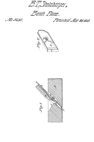
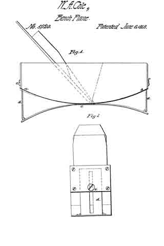
Figure 1 is a side elevation of the plane. Fig. 2 is an end view.

Similar letters refer to similar parts, in both figures.

The nature of my invention, consists in an improvement in the construction of the plane, by which I am enabled to curve the face of the plane either concave or convex, and regulate the face of the said plane so as to plane various curves with the same plane.

In making my improvements I take an ordinary plane, with the plane irons, &c., as usual, I then cut a convex face upon it as seen at (a–b). To the face thus prepared I attach a plate of metal (c), at the center, the length and width of the plane; at the center there is a slot cut across through which the edge of the cutting iron may pass. At each end of the plate (c) there is a slide (d) connected, which passes up against the front and back of the plane, beneath a plate of brass, space being left sufficient to allow it to pass up and down.

In operating this plane, the face plate (c) is set to the desired curve, by pushing the pieces (d) down, these are then confined in their places, by a screw (e) upon the ends of the plane as represented. It will be seen that concave and convex surfaces can be planed by this instrument, and that it can be adjusted to any desired curve, as set forth and described above.

What I claim as my invention and improvement, and desire to secure by Letters Patent, is —

The adjustable metallic spring plate, secured to the face of the plane for the purpose of planing with one plane, various curves either concave or convex, substantially as herein described and set forth.

WM. A. COLE.

Witnesses:
A. W. KELLOGG,
I. P. PIRSSON.

No. 5,486 – Joiner’s Plane (Benjamin F. Shelabarger) (1848)

[paiddownloads id=”21″]5486


UNITED STATES PATENT OFFICE.

_________________

BENJ. F. SHELABARGER, OF MIFFLINTOWN, PENNSYLVANIA.

JOINER’S PLANE

_________________

Specification of Letters Patent No. 5,486, dated March 28, 1848.

_________________

To all whom it may concern:

Be it known that I, BENJ. F. SHELABARGER, of Mifflintown, in the county of Juniata and State of Pennsylvania, have invented a new and useful Improvement in Planes for Working Lumber ; and I do hereby declare the following to be a full, clear, and exact description thereof, reference being had to the accompanying drawings, making a part of this specification.

The nature of my invention consists in combining an adjustable metallic throat piece, with a plane iron and stock, in such a manner that the discharging aperture for the shavings will not be rendered imperfect or enlarged by the wearing away of the plane stock.

In the accompanying drawings Figure 1, is a vertical longitudinal section of a plane having my improved adjustable throat piece, combined with the same, and Fig. 2, is a perspective view of the throat piece detached.

A, is the plane stock.
a is the adjustable throat piece.
b, is the plane iron.
c, is a set screw, securing the plane iron to the throat piece.
e, is a slot in the plane iron, through which the screw c, passes.
d, is the tightening wedge, which secures the plane iron and throat piece within the plane stock.

The throat piece has a bearing surface a’ at its lower end, between which and the front side of the plane iron there is a space for the shavings to pass between, and out through the aperture g, in the throat piece, into the enlarged discharging throat f, in the plane stock. The enlarged discharging throat f, descends to about one half the depth of the stock; from the bottom of this enlarged throat, there is carried down to the base of the plane, a mortise with parallel sides, just large enough to receive the adjustable throat piece with the plane iron attached to it. It will readily be perceived therefore, that the bearing surface of the throat piece in front of the cutting edge of the plane iron, can be adjusted, as the stock wears away, so as to be always on a line with the face of the plane stock. The aperture between the bearing surface a’, of the throat piece, and the plane iron, — for the passage of shavings, — will remain perfect and of the same size till the plane stock is worn out; when the throat piece may be placed in a new stock. The advantage of having a perfect shaped discharging aperture in planes for the escape of the shavings, is so apparent, and so well known by all who are familiar with the use of this tool, that it is not necessary to dwell upon the subject. With planes, as now constructed, the discharging aperture for shavings, immediately in front of the plane irons, is constantly increasing in size, by the wearing away of the base of the plane stock. My adjustable metallic throat piece perfectly obviates this difliculty. My adjustable throat pieces I intend to apply to planes of all shapes and descriptions; the bearing surface of the throat piece, in all cases to correspond with the face of the planes. The aperture g, in the throat piece, extends upward a suflicient distance to allow the shavings to escape freely into the space.

What I claim as my invention and desire to secure by Letters Patent, is —

The combination of an adjustable metallic throat piece, with the irons and stocks of planes of all descriptions, substantially in the manner and for the purpose herein set forth.

BENJAMIN F. SHELABARGER.

Witnesses:
R. BARNARD,
SAML. C. FORREY.