No. 6,459 – Bench Plane (Charles S. Beardsley) (1849)
UNITED STATES PATENT OFFICE.
_________________
C. S. BEARDSLEY, OF AUBURN, AND S. WOOD, OF NEW YORK, N. Y.
BENCH PLANE.
_________________
Specification of Letters Patent No. 6,459, dated May 22,1849.
_________________
To all whom it may concern:
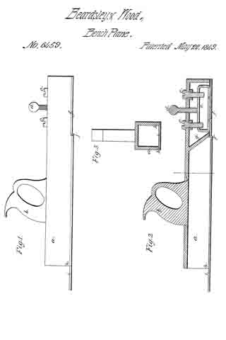
Be it known that we, CHARLES S. BEARDSLEY, of Auburn, in the county of Cayuga, and SIMEON WOOD, of the city, county, and State of New York, have invented new and useful Improvements in Hand and Bench Planes, and that the following is a full, clear, and exact description of the principle or character which distinguishes them from all other things before known, and of the manner of making, constructing, and using the same, reference being had to the accompanying drawings, making part of this specification, in which —
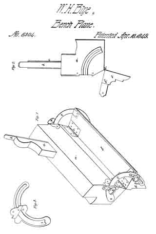
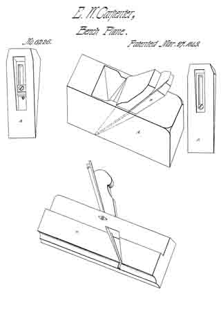
Figure 1 is a side elevation of a hand plane on our improved plan; Fig. 2, a longi-tudinal vertical section; and Fig. 3, a cross section.
The same letters indicate like parts in all the figures.
In the hand plane as heretofore and now universally used the entire surface is on the same level, and the bit or cutting edge projects beyond it to the extent of the thickness of the shaving intended to be cut, the consequence of this is that the forward part of the surface of the plane can rest on the surface of the board forward of the shaving for that constitutes the gage to determine the thickness of shaving to be cut; but back of the cutting edge the surface of the board is reduced below the level of the forward part to the extent of the thickness of the shaving cut while the surface of the plane back of the cutting edge is on the same level with the forward part, and therefore if the back part of the plane be borne down it must be depressed and only rest on the planed surface at the back edge instead of along its entire length. The rear part, which runs on the planed surface, should be the guide to direct the plane, and for this purpose should have its whole surface running on the board and the forward part should only act as a gage and should therefore be on a higher level; but with the construction of the common plane this is not possible for the reasons mentioned.
The object of our invention is to avoid the defect of the common plane, and to this end the nature of the iirst part of our invention consists in making the surface of the plane from the cutting edge back on a level with the cutting edge, and the surface forward of the cutting edge parallel with the rear part, but movable and adjustable that it may be set so much above the level of the rear part as to determine the thickness of the shaving to be cut and constitute a gage for this purpose, and thus permit the entire surface of the plane back of the cutting edge to rest and run on the planed surface while the forward part or gage runs on the part from which the shaving has not been cut. And our invention also consists in making one surface of the planing bit or cutter the rear part of the surface of the plane, when this is combined with the making of the rear part of the stock, from the throat of the plane to the back, hollow for the passage and discharge of the shavings.
In the accompanying drawings (a) represents the stock of the plane which is made of iron and hollow. It is provided at top with a handle (b) in the usual manner, and the forward part is provided with these screws (c, c) and (d), the two (c, c) are tapped into a projection (e) of a gage plate (f) so that by the turning of these screws the gage plate will be elevated, and the other screw (d) is tapped into the stock and its end bears on the top of the projection (e)
for the purpose of forcing it down. In this way the gage plate can be regulated and set with accuracy. The side edges of the gage plate are adapted to slide freely and accurately within the hollow stock, and the rear edge which should be made at right angles with the sides of the stock, is so formed as to constitute, when in place, the continuation of a partition plate or flanch (g) which connects the two sides of the stock, and the rear face of this partition or flanch is inclined back toward the rear of the stock and gradually looses itself in the top plate of the stock which then runs horizontally to the back end. This forms what takes the place of the forward face of the throat of the ordinary plane.
The sides (h, h) of the hollow stock, inside and near the lower edge are grooved to receive the plane bit or cutter (i) which is a flat plate of metal, with the lower face perfectly true and parallel with the face of the gage plate while its upper face is parallel with the under face except at the forward end (j) where it is beveled down to form the cutting edge. This bit or cutter is thus inserted by sliding it in the grooves of the stock until the cutting edge is brought so near the rear edge of the gage plate as to form the throat of the plane for the passage of the shavings. In this way the throat is formed by the rear edge of the gage plate the flanch and the bevel of the bit or cutter, and the continuation of this throat for the delivery of the shavings at the rear is formed by the hollow stock. The lower edges of the sides of the stock should be chamfered off slightly in an upward direction at the sides of the cutting end of the bit, and then run to the forward end so much above the level of the face of the plane as to be above the greatest height to which the gage plate may be set for the greatest thickness of shaving. The under face of the gage plate should be parallel with the face of the plane back of the cutting edge but this is not indispensable. The planing bit may be inserted in the stock in any other manner as this does not constitute an essential part of our invention, and so of the gage plate it may be connected with the stock in any other desired manner, as for instance, it may be provided with projections at the sides fitted to slide in inclined grooves in the cheeks of the stock, and provided with a set screw to move toward or from the cutting edge of the bit, the inclination of the grooves having the effect to depress or elevate it while at the same time it reduces or increases the size of the throat.
The first part of our invention may be applied without the second by making the surface back of the cutting edge a part of the stock and inserting a separate bit, which may be done either by making a mortise through the sides or cheeks of the stock, or by inserting the bit and making the throat in the usual manner.
It will be obvious to those acquainted with the art of making and using planes that our improvements are applicabie to all kinds of hand planes for plain and ornamental work, the same construction and arrangement being applicable to all varieties, and the variations required being simply in the form.
We claim:
Constructing and applying the bit or cutter, substantially as described, that its lower surface may constitute that part of the surface of the plane back of the cutting edge, in combination with the hollow stock for the passage and delivery of shavings, substantially as described.
CHARLES S. BEARDSLEY.
SIMEON WOOD.
Witnesses:
A. P. BROWN, Sr.,
A. E. PETERS.