No. 7,543 – Scraper Used By Cabinetmakers (Hiram Carver) (1850)

[paiddownloads id=”5″]7543


UNITED STATES PATENT OFFICE.

_________________

HIRAM GARVER, OF EDINBURG, VIRGINIA.

SCRAPER USED BY CABINETIVIAKERS.

_________________

Specification of Letters Patent No. 7,543, dated August 6, 1850.

_________________

To all whom it may concern:

Be it known that I, HIRAM CARVER, of Edinburg, county of Shenandoah, and State of Virginia, have invented a new and useful Improvement in Cabinetmakers’ Scraping-Tools, and that the following is a full, clear, and exact description thereof, reference being had to the accompanying drawings, which make part of this specification.

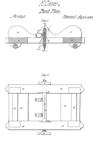
The scraper in common use is a plate of steel of any convenient size and generally of uniform thickness, like a piece of common saw plate. An edge of this plate having been made straight or slightly curved, convexly outward is burnished on the edge with a piece of polished steel so as to raise a slight ridge or feathering on each corner as seen at e, e, and e’, e”, Fig. 1. Such plate is, when used to smooth off furniture, coach bodies, panelings and other work requiring to be brought to a smooth surface, usually held by the workmen between the thumbs and fingers of his two hands, and with the top inclined from him is operated by pushing, while the lower inclined feathered corner scrapes the surface and removes the irregularities left by the plane. This mode of using the scraper is excessively fatiguing to the lingers and thumbs and without great strength cannot be long pursued, nor without great steadiness of hand can the work be made of uniform smoothness. To remedy these inconveniences, and to make the scraper a convenient and efficient tool I furnish the scraping plate A with a stock (B) in which it is set, and held fast by set screws (C) or other equivalent device. The stock-frame D is a little wider than the plate A, and the stock has a slot quite through it, allowing the plate to come above the upper edge, as well as to descend below the lower edge of the stock.

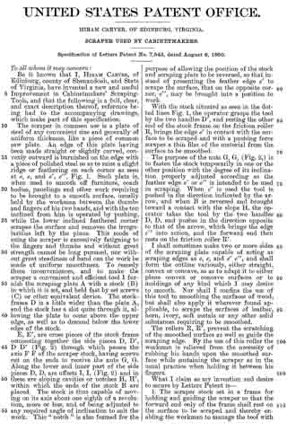
E, E’, are cross pieces of the stock frame connecting together the side pieces D, D’, D D’ (Fig. 2) through which passes the axis F F of the scraper stock, having screws cut on the ends to receive the nuts G, G.

Along the lower and inner part of the side pieces D, D, are offsets I, I, (Fig. 2) and in these are sloping cavities or notches H, H’, within which the ends of the stock B are placed. The stock is thus capable of moving on its axis about one eighth of a revolution, more or less, and of being adjusted to any required angle of inclination to suit the work. This “notch” is also formed for the purpose of allowing the position of the stock and scraping plate to be reversed, so that instead of presenting the feather edge e’ to scrape the surface, that on the opposite corner, e”, may be brought into a position to work.

With the stock situated as seen in the dotted lines Fig. 1, the operator grasps the tool by the two handles D’, and resting the other end of the stock frame on the friction roller R, brings the edge e’ in contact with the surface to be scraped and with a pushing force scrapes a thin film of the material from the surface to be smoothed.

The purpose of the nuts G, G, (Fig. 2,) is to fasten the stock temporarily in one or the other position with the degree of its inciination properly adjusted according as the feather edge e’ or e” is intended to be used in scraping. When e’ is used the tool is pushed in the direction indicated by the arrow, and when B is reversed and brought toward a contact with the slope H, the operator takes the tool by the two handles D, D, and pushes in the direction opposite to that of the arrow, which brings the edge e” into action, and the forward end then rests on the friction roller R’.

I shall sometimes make two or more sides of the scraping plate capable of acting as scraping edges as e, e, and e’ e”, and shall form the outline variously, either straight, convex or concave, so as to adapt it to either plane convex or concave surfaces or to moldings of any kind which I may desire to smooth. Nor shall I confine the use of this tool to smoothing the surfaces of wood, but shall also apply it wherever found applicable, to scrape the surfaces of leather, horn, ivory, soft metals or any other solid substances requiring to be smoothed.

The rollers R, R’, prevent the scratching of the smoothed surface as well as guide the scraping edge. By the use of this roller the workman is relieved from the necessity of rubbing his hands upon the smoothed surface while sustaining the scraper as in the usual practice when holding it between his fingers.

What I claim as my invention and desire to secure by Letters Patent is —

1. The scraper stock set in a frame for holding and guiding the scraper so that the forward end only of the frame shall rest on the surface to be scraped and thereby enabling the workman to manage the tool with the whole hand, and apply a steady force; instead of using the fingers only as heretofore for that purpose.

2. I also claim reversing the position of the scraper stock and plate in the frame, whereby I am enabled to use both feather edges or corners of the plate successively without taking the plate from the stock as herein set forth.

HIRAM CARVER.

Witnesses:
WALTER R. JOHNSON,
JOHN B. STONER.

No. 7,432 – Plane For Tonguing And Grooving Boards (James A. Woodbury) (1850)

[paiddownloads id=”4″]7432


UNITED STATES PATENT OFFICE.

_________________

JAMES A. WOODBURY, OF BOSTON, MASSACHUSETTS.

PLANE FOR TONGUING AND GROOVING BOARDS, &c.

_________________

Specification of Letters Patent No. 7,432, dated June 11, 1850.

_________________

To all whom it may concern:

Be it known that I, JAMES A. WOODBURY, of Boston, in the county of Suffolk and State of Massachusetts, have invented certain new and useful Improvements in Apparatus for Tonguing and Grooving Boards, Planks, &c., and that the following description, taken in connection with the accompanying drawings hereinafter referred to, forms a full and exact specification of the same, wherein I have set forth the nature and principles of my said improvements by which my invention may be distinguished from others of a similar class together with such parts as I claim and desire to have secured to me by Letters Patent.

The figures of the accompanying plate of drawings represent my improvements.

Figure 1 is a side elevation of hand plane arranged with my improvements for cutting, or forming tongues in boards or planks. Fig. 2 is a top view of the same.

Fig. 3 is an isometrical perspective view of a gouge used in said plane, and Fig. 4 is a similar view of a smoothing chisel set behind this gouge in said plane; and Fig. 5 is a plan of the underside of said plane, and Fig. 6 is an end view of the same. Precisely similar views of a hand plane for forming grooves in boards or planks, to those represented in Figs. 1, 2, 3, 4, 5 and 6, are shown respectively in Figs. 7, 8, 9, 10, 11 and 12.

As the implements for forming tongues and grooves are now arranged, there is but a single cutting chisel of the ordinary shape or construction, the edge of which penetrates into the wood, and tears out the shaving from the sides of the groove or tongue, and leaves said sides rough and imperfect. While in cross-grained lumber and wet wood it is almost impossible to form a tongue or groove with the tools now in common use.

The defective operation of the tools heretofore devised, in the particular above noted, has long been sought to be remedied, and by my improvements the difliculties and imperfections above referred to are entirely obviated.

In my improved apparatus I use two cutting tools or chisels. That which first enters the wood is a gouge-cutter with a semi-circular cutting edge, which operates to take out the greater portion of the shaving required to be removed from the groove, or on each side of the tongue. And behind this gouge cutter is set a smoothing cutter havlng a common chisel edge at the bottom, and on each side thereof a cutting or face, the chisel edge operating to smooth the bottom of the groove &c., and the cutting lips serving to smooth the sides of the grooves and tongues.

The two hand planes shown in the drawings, are constructed in most respects, in the plane stocks, like those in common use for forming tongues and grooves. The handles of both stocks are shown at a a–a a, Figs. 1 and 7, and the guiding ledges which fit against the face of the boards or planks, are shown at b b–b b, in said figures, and in Figs. 5, 6, 11 and 12. They are both also contrived in the usual way, with the wooden wedges, c c c &c., Figs. 1 and 2, 7 and 8, for confining the cutting tools in proper position. The plane for forming the tongue has two sets or series of gouges and smoothing chisels, above referred to, as shown at d, e–d, e, Figs. 1, 2 and 5, and two throats, f f–g g, on each side for the delivery or escape of the shavings, as shown in said Figs. 1 and 2. It also has the usual groove, h h, Figs. 5 and 6, on its under side, which fits, and plays over the tongue as it is made.

The grooving plane requires discharging throats but on one side, and has the usual tongue, i i, Figs. 7, 11 and 12, along its under side through which the cutting tools pass, and which fits into, and plays through the groove, as it is made deeper and deeper in the board or plank.

As before suggested, and explained, the main feature of my invention consists in the use of gouges, d–d, in the tonguing plane, and k, in the grooving plane, to precede a smoothing tool, e–e and l, in said tonguing and grooving planes respectively; the said smoothing tools having lips to cut smoothly on the sides of the grooves and tongues to be formed. The gouges, d–d and k, have semi-circular cutting edges, and should be so set in the plane stocks, see Figs. 1 and 5, 7 and 11, as that the corners should penetrate into, and engage with the wood first, so as to turn the shavings up into the discharging throats freely. The smoothing irons in the tonguing plane have but one smoothing lip or face, as shown at m, Figs. 4 and 5, there being two such tools the front or cutting edge of the lip of one of which cuts on each side of the tongue, while the grooving plane has but one such tool, with a lip, n–n, on each side, the front or cutting edge of which serves to smooth each side of the groove. The smoothing tools which are set behind the gouges in both plane-stocks, shown in the drawings, should, like the gouges, to be so fixed in position, as the upper corners of the front or cutting edges of the side lips, m–n, n, shall first engage with, and penetrate the wood, as, by thus arranging them a “drawing stroke,” (so to speak,) is produced, as the planes are moved along, and the shavings, as before suggested, are more freely discharged through the throats formed in the stocks for the purpose.

It will be evident to any mechanic versed in the arts of carpentry or joinery, that the arrangement of tools for forming tongues and grooves hereinabove suggested, and described, may be used in stationary positions in a manner which will be readily understood, on the sides of power planing machines; or a series of alternate gouges smoothing cutters constructed as above described, may be set in a revolving frame or stock, and produce a much improved result on that which is now effected in such machines. A sufficient number of alternate gouges and smoothing cutters, should be used to out the tongue or groove of any required depth, by passing the board or plank once through the machine. The great end attained by any of the arrangements above described being the removal first by the gouges of the larger portion of the shaving, and then smoothing the sides and bottom of the grooves and sides faces of the tongues and the sunken or rebated edges adjacent to the same, by the smoothing tool, having the lips as described.

Having thus described my improvements, in tonguing and grooving apparatus, I shall state my claim as follows:

What I claim as my invention, and desire to have secured to me by Letters Patent in said apparatus, is —

The combination of a gouge or gouges, (for removing the bulk or greater portion of a shaving in forming tongues or grooves in boards or planks,) with smoothing tools having a chisel edge, a cutting and side lip on either or both sides thereof, (for smoothing the sides and bottom of the grooves, and the edges about the tongues, as set forth) ; said gouges being set in front of said smoothing tools, and the whole being arranged, and operating substantially, as hereinabove set forth.

Boston March 13th 1850.
JAMES A. WOODBURY.

Witnesses:
EZRA LINCOLN,
ROBERT L. HARRIS.