
No. 644,191 – Carpenter’s Plane (Abraham W. Stauffer) (1900)
UNITED STATES PATENT OFFICE.
_________________
ABRAHAM W. STAUFFER, OF PHILADELPHIA, PENNSYLVANIA.
CARPENTER’S PLANE.
_________________
SPECIFICATION forming part of Letters Patent No. 644,191, dated February 27, 1900.
Application filed May 6, 1899. Serial No. 715,818. (No model.)
_________________
To all whom it may concern:
Be it known that I, ABRAHAM W. STAUFFER, a citizen of the United States, residing at Philadelphia, in the county of Philadelphia and State of Pennsylvania, have invented a certain new and useful Improvement in Carpenters’ Planes, of which the following is a specification.
My invention relates to a new and useful improvement in carpenters’ planes, and has for its object to provide a simple and effective means for adjusting the blade of the plane either up and down or sidewise and for clamping and holding the blade firmly in position.
With these ends in view this invention consists in the details of construction and combination of elements hereinafter set forth and then specifically designated by the claims.
In order that those skilled in the art to which this invention appertains may understand how to make and use the same, the construction and operation will now be described in detail, referring to the accompanying drawings, forming a part of this specification, in which —
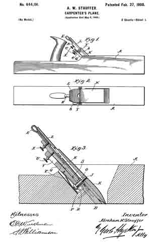
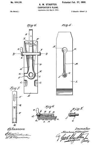
Figure 1 is a side view of the plane having my improvements embodied therein; Fig. 2, a plan view thereof; Fig. 3, an enlarged section of a portion of the stock of the plane, showing my improvements in section and in position; Fig. 4, a detail view of the bed-block removed from the stock and showing the device for adjusting the bit; Fig. 5, a similar view of the back of the bit; Fig. 6, a section at the line y y of Fig. 4; Fig. 7, a detail view of the clamping-bar, and Fig. 8 represents the clamping-screw.
In carrying out my invention as here embodied, A represents the plane-stock, having fitted therein the bed-block B, which is adjustably secured within the throat of the plane by means of suitable screws passing through the slots C and into the stock. The upper surface of the bed-block is recessed, as shown at D, so as to receive the adjusting-lever E, which has a fulcrum extension F, upon which this lever rocks when being manipulated, said extension fitting within the recess G, formed for that purpose. The adjusting-lever has a hole H formed therein, which registers with the elongated hole I, formed in the bed-block, and through these two holes passes the clamping-screw J, the latter being threaded into the clamp-plate K. This plate is adapted to fit upon the upper surface of the bit L when the latter is in position upon the bed-block, forming a cap therefor, and the clamping-screw J passes through the slot M, formed in the bit, the upper end of which slot is enlarged, as at N , in order that the head of the screw may be withdrawn from the bit. A washer O is placed around the screw and bears against the under side of the bit, and a bushing P is interposed between this washer and the head of the screw in order that when the said screw is run into the clamp-plate the washer will be firmly bound against the under side of the bit, while the clamp-plate will be as firmly bound against the upper surface of the bit, thus tightly securing these parts together. When not assembled, the washer lies within the hole H in the adjusting-lever, permitting the latter to swing thereon.
Q is the clamping-bar, slotted at its lower end, as indicated at R, so as to embrace the screw and bushing thereon and be adapted to draw downward upon the head of said screw. This bar has a ridge S thereon, which acts as a fulcrum, bearing against the under side of the bed-block, so that when the outer end of the bar is forced upward, as hereinafter set forth, the lower end will be swung downward, as will be readily understood, thereby drawing with it the clamping-screw, and consequently the clamp-plate and bit. This action will force the bit firmly against the bed-block, thus holding it against any movement while the plane is in use. A plate-spring T is secured to the under side of the clamping-bar, so as to hold the latter in position and yet permit its movements when being operated to bring about the above-named results.
In order that the outer end of the clamping-bar may be drawn upward with sufficient force to accomplish the results aimed at, a thumb-screw U is passed through the slot V, formed in the bar and threaded in the bed-block, as clearly shown in Fig. 3, and, as is obvious, when this screw is run upon the bed-block it will draw the outer end of the bar upward, the purpose of the slot being to permit the withdrawal of the clamping-bar from the stock when it is desired to release the clamping-screw, and thereby permit the removal of the bit and parts carried thereby.
The upper portion of the bed-block is slotted, as shown at W, and through this slot passes a thumb-screw X, its inner end being threaded into the adjusting-lever E, so that when said lever has been swung to the position which properly adjusts the bit it may be there held by properly manipulating this thumb-screw.
While the bit under ordinary conditions will be held in its adjustment by the clamp-plate, the use of the screw X to hold the adjusting-lever will permit said lever also to act as a means for holding the bit in its adjustment, since so long as the adjusting-lever is held against movement the bit cannot have any lengthwise movement on account of the washer O fitting snugly within the hole H.
The means which I provide for the sidewise adjustment of the bit, which enables the cutting edge of the latter to be properly trued up, is as follows: A cross-slide Y is fitted in dovetailed grooves formed in the bed-block and has lips a formed upon its ends, which embrace the bit, and the movements of this slide are controlled by the spiral cam b, which projects into the groove formed in the slide, said cam being pivoted to the bed-block by the screw d. A thumb-lever e is formed with the cam for its manipulation, so that by drawing this lever to one side or the other the slide will be moved crosswise of the bed-block, and thereby swing the bit upon the washer O as the fulcrum, which, as is obvious, will adjust the cutting edge of the bit, and thereby permit the truing up of the same.
From this description it will be seen that effective means are provided for the adjusting of the bit vertically and also for the truing up of the same, as well as providing for firmly clamping the bit in any adjustment, the latter being especially true since the entire under surface of the clamp-plate fits against the bit, while the under surface of the bit fits against the bed-block, so that when the clamp-plate is drawn downward it will firmly hold said bit.
Having thus fully described my invention, what I claim as new and useful is —
1. In combination with a plane of the character described, a bed-block adjustably secured within the stock, an adjusting-lever fitted within a recess formed in the bed-block, an extension formed with the adjusting-lever and fitted within the recess in the stock, said lever having a hole therethrough, a bit having a central slot therein, a clamp-plate adapted to fit upon the upper surface of the bit, a clamping-screw threaded into the plate, a washer surrounding the screw and adapted to bear against the under side of the bit and fit within a hole formed in the adjusting-lever, a bushing also surrounding the screw and bearing against the washer, a clamping-bar fulcrumed against the under side of the bed-block having its lower end slotted to engage the head of the screw, and means — such as a thumb-screw for drawing the upper end of the clamping-bar toward the bed-block whereby the lower end thereof will be caused to draw the screw and the parts carried thereby downward, as and for the purpose set forth.
2. In combination with a plane of the character described, a bed-block adjustably secured within the stock, an adjusting-lever, an extension formed with the adjusting-lever, a bit adjusted thereby, a clamp-plate, a clamping-screw, a washer and bushing surrounding said screw, a clamping-bar and means for operating the same.
In testimony whereof I have hereunto affixed my signature in the presence of two subscribing witnesses.
ABRAHAM W. STAUFFER.
Witnesses:
MARY E. HAMER,
S. S. WILLIAMSON.