No. 591,663 – Plane (Andrew Turnbull) (1897)

UNITED STATES PATENT OFFICE.
_________________
ANDREW TURNBULL, OF NEW BRITAIN, CONNECTICUT,
ASSIGNOR TO JUSTUS A. TRAUT, OF SAME PLACE.
PLANE.
_________________
SPECIFICATION forming part of Letters Patent No. 591,663, dated October 12, 1897.
Application filed June 30, 1897. Serial No. 642,947. (No model.)
_________________
To all whom it may concern:
Be it known that I, ANDREW TURNBULL, a citizen of the United States, residing in New Britain, in the county of Hartford and State of Connecticut, have invented certain new and useful Improvements in Planes, of which the following is a specification.
This invention relates to planes; and the object thereof is to provide a simple and efficient means for holding the cutter-clamp firmly in engagement with the cutter; and it consists, essentially, of a cam-lever supported by the clamp, a locker preferably separate from and actuated by the cam-lever, and means on the clamp to cause the lever to approach and to recede from the clamp when the lever is turned.
In the form of the invention illustrated the locker alluded to consists of a pivot for the cam-lever loosely extending through an opening in the clamp and headed at its lower end, the lever having a cam portion adapted to be engaged by means on the clamp when the lever is turned in one direction, so that the lever will be caused to approach the cutter and thereby force the head of the pivot tightly against the cutter to hold the same.
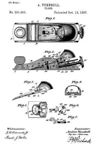
In the drawings accompanying and forming part of this specification, Figure 1 is a plan view of a plane embodying my present improvements. Fig. 2 is a longitudinal central section of the same. Fig. 3 is a longitudinal central section of the cutter-clamp. Fig. 4 is a transverse section taken in line x x, Fig. 3. Fig. 5 is a bottom view of a portion of the cutter-clamp. Fig. 6 is a plan of the cam-lever, and Fig. 7 is a side elevation of the same.
Similar characters designate like parts in all the figures of the drawings.
The body of the plane is designated in a general way by B, and it consists of the usual base or sole 2, having the transverse mouth 3, through which the cutting edge of the plane-iron can pass, and the longitudinal side walls 5.
The cutter or plane-iron C, which is supported in any usual manner, as shown in Fig. 2, and the clamp-lever D may be of ordinary construction. The cutter C is supported against the inclined face 7 on the inside of the sole 2, said cutter, also bearing intermediate its opposite ends against the obliquely-disposed slide 12, working in a slide-way 13 of the boss or projection 14 on the sole 2. The boss or projection 14 has a longitudinally-threaded opening 15 to receive the threaded end 16 of the screw or spindle 17 , having at its outer end the disk or wheel 13, by which the screw 17 can be turned into and out of its seat, said screw having a peripheral groove 19 to receive a projection 20 on the slide 12, the other end of the slide being furnished with an oppositely-extending projection 21, adapted to be seated in one of the parallel notches 22, transversely formed in the under side of the cutter or plane-iron C, so that by turning the screw or spindle 17, through the medium of the disk or wheel 18, the cutter C can be moved back and forth, as occasion demands.
The foregoing description relates to a common form of smooth-plane to which my present improvements are adapted, although it is obvious that they may be applied to various sorts of planes. The clamp-lever D is held in place longitudinally by a screw 23, seated in a threaded aperture in the boss 10, said screw extending through an elongated or keyhole slot 24; near the forward end of the clamp.
The clamp D carries or supports a cam-lever L, consisting of a disk portion 30, centrally through which is passed the pivot-pin 31, constituting a locker, and a forwardly-extending curved operating-arm 32, passing through the segmental or curved slot 33 in the clamp, said operating-arm having a thumb-piece 34, to which pressure can be applied to turn the cam-lever L, so that the disk or working portion 30 of the lever will be caused to approach or recede from the cutter or plane-iron C in accordance with the direction in which the arm 32 is moved.
The pivot-pin 31 of the cam-lever loosely passes transversely through the clamp, it extending through the opening 35 in the bridge-piece or arch 36, which is on and is located above the normal plane of said clamp. The pivot-pin, which constitutes a cutter-locker, is headed or shouldered at its lower end, as at 37, and the disk or cam portion of the lever L, when the latter approaches the cutter, will act against the head 37 of the pivot-pin to force the same firmly against the cutter. The upper end of the pivot-pin is headed, as at 37’, to prevent it from dropping on the removal of the clamp.
For the purpose of obtaining the necessary motion of the lever toward the cutter the clamp is preferably provided with means adapted to engage a cam portion on the lever, as will now appear. The bridge portion 36 is furnished with the rounded projections 38 and 39, extending oppositely from the pivot-opening 35, and adapted to cooperate with the cam portions on the disk 30 of the cam-lever L. The upper face of the disk 30 is intersected by the radial cam-recesses 40 and 41 of differential depth, thereby to form the cam-faces 42 and 43, cooperative, respectively, with the projections 38 and 39.
When the parts are to be assembled, the clamping-screw 23 is passed through the wide portion of the slot and the clamp slid forward until the screw is in the narrow part of the slot 24, as shown in Fig. 1, the operating-arm 32 of the cam-lever during this time being in a position substantially agreeing with that shown by the dotted lines in said figure, at which time the two projections 38 and 39 on the bridge-piece are in line with the deepest portion of the cam-recesses. When the operating-arm 32 is grasped and thrown to the position shown by the full lines in Fig. 1, the cam portions 42 and 43 will be caused to ride against the projections 38 and 39,respectively, so that the disk portion 30 of the lever will be lowered and acting against the head 37 of the pivot-pin 31 will cause said head to bind against the cutter to lock the same firmly in position, the operating-arm of the lever also tightly wedging against the clamp to thereby prevent the retraction of the lever by ordinary jars. It will be observed that the operating-arm 32 of the cam-lever L, which extends forward and passes through the longitudinal slot 33 in the clamp, bears against the plate portion 33′ of the clamp, as indicated in Fig. 2, so that the clamp or plate portion thereof acts as a support for said operating-arm and materially decreases its liability of breakage.
Having described my invention, I claim —
1. A plane embodying a cutter; a clamp therefor provided with a bridge-piece or arch located above the normal plane of the clamp, the bridge-piece having a pivot-opening and also having projections on its under face; a lever consisting of a disk portion and an operating-arm passing through a slot in the clamp, the disk portion of the lever having a pivot-opening and a plurality of cam-recesses; and a pivot- pin extending through said pivot-openings and headed at its lower end, the pin being disposed transversely to the cutter, whereby when the lever is turned in a direction to lock the cutter the under face of the disk portion will be carried against the head of the pin to move the latter into locking engagement with said cutter.
2. A plane embodying a cutter; a clamp therefor provided with a bridge-piece having a pivot-opening, the bridge-piece having on its under face oppositely-disposed projections at each side of the pivot-opening, said clamp being also slotted; a lever consisting of a disk portion and an operating-arm extending through the slot in the clamp, the disk portion of the lever having a pivot-opening and a plurality of cam-recesses; and a pivot-pin extending through said pivot-openings and headed at its lower end.
3. A plane embodying a cutter; a clamp therefor having a slot; a cam-lever supported by the clamp, the latter having means to cause the working end of the lever to approach and recede from the clamp on the manipulation of the lever, and the lever being provided with a forwardly-extending arm passing through the slot and bearing against and sustained by the clamp; and a locker for the cutter, operated by said lever.
ANDREW TURNBULL.
Witnesses:
H. C. HINE,
W. A. PRIMM.


