
No. 20,493 – Bench Plane (H. Lee Kendall) (1858)
UNITED STATES PATENT OFFICE.
_________________
H. L. KENDALL, OF BALTIMORE, MARYLAND.
BENCH-PLANE.
_________________
Specification of Letters Patent No. 20,493, dated June 8, 1858.
_________________
To all whom it may concern:
Be it known that I, H. L. KENDALL, of the city of Baltimore and State of Maryland, have invented a new and useful Improvement in Bench-Planes; and I do hereby declare that the following is a full, clear, and exact description of the construction and operation of the same, reference being had to the annexed drawing, forming part of this specification, in which —
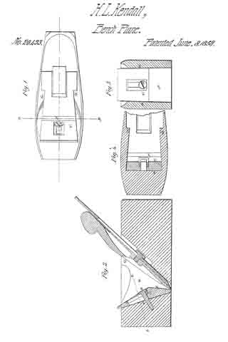
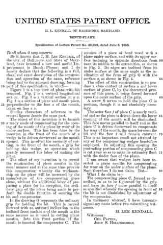
Figure 1 is a top view of plane with bit removed. Fig. 2. is a vertical longitudinal section. Fig. 3 is a vertical section on y y. Fig. 4 is a section of plane and mouth piece, perpendicular to the face on of the mouth, taken on line z z.
Similar characters of reference in the several figures denote the same part.
The object of this invention is to furnish a ready mode of compensating for the opening of the mouth of the plane by wear of its under surface. This has been done by the insertion in the front of the mouth of a wedge to be driven downward as the mouth opened. This involved the necessity of cutting, in the front of the mouth, a grip for holding this wedge, an operation which greatly increased the labor of making the plane.
The effect of my invention is to permit the construction of plane mouths in the usual manner and at the same time provide this compensator, whereby the workmanship on the plane will be increased by the manufacture of the compensating piece alone, without the additional labor of preparing a place for its reception, the ordinary grip of the plane being made to perform the double function of securing the bit and compensator.
In the drawing G represents the ordinary grip for holding the bit. This is carried forward with an outward inclination to the inclined front surface a of the mouth in the same manner as is usual in cutting plane mouths. Into this front portion of the mouth is inserted the compensator C. This consists of a piece of hard wood with a plane under surface, and with its upper surface. inclining in opposite directions from near its middle to its extremities, as shown in Fig. 2. Its edges are inclined from its under surface at the same angle as the inclination of the faces of grip G with the surface a, as shown in Fig. 4.
The effect of this construction is to produce a close contact of surface a and lower surface of piece C, by the downward pressure of this piece, it being forced forward upon the outer surface of the grip.
A screw S serves to hold the piece C in position, though it is not absolutely necessary.
The outer face f of piece C is nearly vertical and as the piece is driven down the lower opening of the mouth will be diminished. This face moves parallel to itself and as the piece C is driven downward to compensate for wear of the mouth, the space between the bit and the face f will remain constant. This is an important result not attained by any of the compensating wedges heretofore employed. In adjusting this opening the protruding portion of compensating piece C is cut away so as to make its extremity flush with the under face of the plane.
I am aware that wedges have been inserted in plane mouths for compensating for wear on the under surface of the plane. Such therefore I do not claim. But —
What I do claim is —
The compensating piece C, formed as described, so as to be tightened by the grip and have its face f move parallel to itself as specified whereby the opening in front of the bit is not diminished by adjustment of the compensator.
In testimony whereof, I have hereunto signed my name before two subscribing witnesses.
H. LEE KENDALL.
Witnesses:
GEO. PATTEN,
JOHN S. HOLLINGSHEAD.