No. 380,811 – Chisel-Gage (Charles L. Mead) (1888)

[paiddownloads id=”433″]380811


UNITED STATES PATENT OFFICE.

_________________

CHARLES L. MEAD, OF NEW YORK, N. Y., ASSIGNOR TO
THE STANLEY RULE AND LEVEL COMPANY, OF NEW BRITAIN, CONNECTICUT.

CHISEL-GAGE.

_________________

SPECIFICATION forming part of Letters Patent No. 380,811, dated April 10, 1888.
Application filed January 26, 1888. Serial No. 261,982. (No model.)

_________________

To all whom it may concern:

Be it known that I, CHARLES L, MEAD, a citizen of the United States, residing at New York, in the county of New York and State of New York, have invented certain new and useful Improvements in Chisel-Gages, of which the following is a specification.

My invention relates to improvements in chisel-gages for use in blind-nailing, and the main object of my improvement is to prevent the shaving turned up from breaking off.

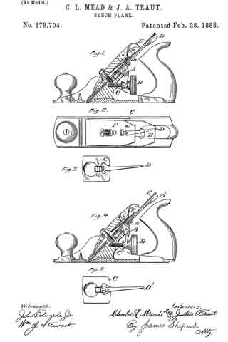
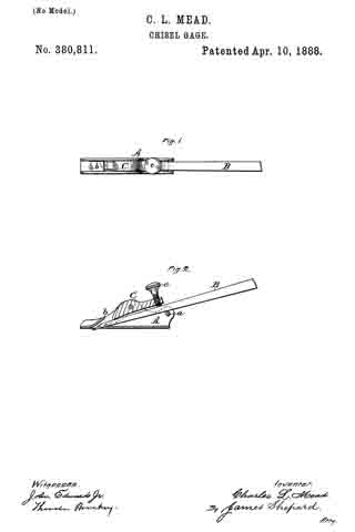
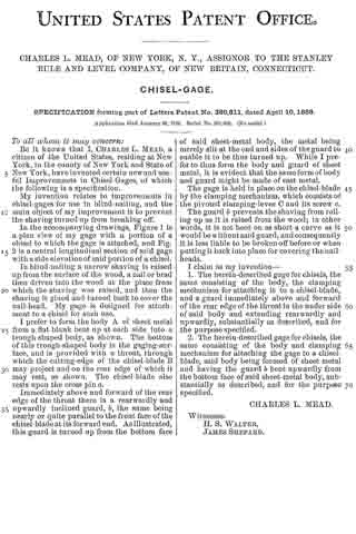
In the accompanying drawings, Figure 1 is a plan view of my gage with a portion of a chisel to which the gage is attached, and Fig. 2 is a central longitudinal section of said gage with a side elevation of said portion of a chisel.

In blind-nailing a narrow shaving is raised up from the surface of the wood, a nail or brad then driven into the wood at the place from which the shaving was raised, and then the shaving is glued and turned back to cover the nail-head. My gage is designed for attachment to a chisel for such use.

I prefer to form the body A of sheet metal from a flat blank bent up at each side into a trough-shaped body, as shown. The bottom of this trough-shaped body is the gaging-surface, and is provided with a throat, through which the cutting-edge of the chisel-blade B may project and on the rear edge of which it may rest, as shown. The chisel-blade also rests upon the cross pin a.

Immediately above and forward of the rear edge of the throat there is a rearwardly and upwardly inclined guard, b, the same being nearly or quite parallel to the front face ofthe chisel-blade at its forward end. As illustrated, this guard is turned up from the bottom face of said sheet-metal body, the metal being merely slit at the end and sides of the guard to enable it to be thus turned up. While I prefer to thus form the body and guard of sheet metal, it is evident that the same form of body and guard might be made of cast metal.

The gage is held in place on the chisel-blade by the clamping mechanism, which consists of the pivoted clamping-lever C and its screw c.

The guard b prevents the shaving from rolling up as it is raised from the wood; in other words, it is not bent on as short a curve as it would be without said guard, and consequently it is less liable to be broken off before or when putting it back into place for covering the nail-heads.

I claim as my invention–

1. The herein-described gage for chisels, the same consisting of the body, the clamping mechanism for attaching it to a chisel-blade, and a guard immediately above and forward of the rear edge of the throat in th under side of said body and extending rearwardly and upwardly, substantially as described, and for the purpose specified.

2. The herein-described gage for chisels, the same consisting of the body and clamping mechanism for attaching the gage to a chisel-blade, said body being formed of sheet metal and having the guard b bent upwardly from the bottom face of said sheet-metal body, substantially as described, and for the purpose specified.

CHARLES L. MEAD.

Witnesses:
H. S. WALTER,
JAMES SHEPARD.

No. 378,704 – Bench-Plane (Charles L. Mead And Justus A. Traut) (1888)

[paiddownloads id=”429″]378704


UNITED STATES PATENT OFFICE.

_________________

CHARLES L. MEAD, OF NEW YORK, N. Y., AND JUSTUS A. TRAUT,
OF NEW BRITAIN, CONNECTICUT.

BENCH-PLANE.

_________________

SPECIFICATION forming part of Letters Patent No. 378,704, dated February 28, 1888.
Application filed August 24, 1885. Serial No. 175,142. (No model.)

_________________

To all whom it may concern:

Be it known that we, CHARLES L. MEAD, of New York, in the county of New York and State of New York, and JUSTUS A. TRAUT, of New Britain, in the county of Hartford and State of Connecticut, both citizens of the United States, have invented certain new and useful Improvements in Bench-Planes, of which the following is a specification.

Our invention relates to improvements in adjusting the plane-irons laterally.

In the accompanying drawings, Figure 1 is a vertical section, partly in elevation, of a bench-plane which embodies our invention. Fig. 2 is a plan view of the same with the holding-cap removed. Fig. 3 is a face view of a portion of the frog and the laterally-adjusting lever. Fig. 4 is a vertical section, partly in elevation, showing a modification of our invention; and Fig. 5 is a face view of a portion of the frog and laterally-adjusting lever of the plane represented in Fig. 4.

We have illustrated our improvement as applied to a Bailey plane, in which the cutter is adjusted up and down by means of the lever A and the nut B; but it may be used in connection with planes having different mechanism for adjusting the cutter up and down. At the upper end of the frog C we pivot the laterally-adjusting lever D, the handle of which lies under the upper end of the cutter E. On the short end of this lever there is an upwardly-projecting pin or stud, a, the length of which pin is longer than the thickness of the cutter E and nearly equal to the combined thickness of the cutter E and the cap-iron F. In use this cap-iron and cutter are secured together by a screw in the ordinary manner. The cap-iron F is provided with a T shaped slot, (shown most clearly in Fig. 2,) the transverse portion of which slot receives the upper end of the adjusting-lever A, while that portion of the slot which extends longitudinally with the cap-iron receives the upper end of the pin a. Inasmuch as the cap-iron has but a very slight up and down movement, the slot for this pin can be made quite short. By turning the lever B to the right or left, as may be required, the upper end of the cap-iron and cutter may be carried to either side, so as to bring their edges square with the stock.

In Figs. 4 and 5 we have shown a modification of our invention, in which we have a similar lever, D’, pivoted in like manner to the frog C; but instead of having a pin in its short end said end is slotted, as shown in Fig. 5, and the cap-iron F has rigidly secured to it a pin, a’, which extends downward through the ordinary slot in the cutter and into the slot of the laterally-adjusting lever. In both constructions the laterally-adjusting lever is made to engage directly with the cap-iron, and is connected thereto by a pin-and-slot connection.

We are aware of the patents to Traut, No. 306,877, October 21, 1885; Gage, No. 323,804, August 4, 1885, and Nicht, No. 173,177 , February 8, 1876, and hereby disclaim all that is shown and described in said patents. By our improvements the construction of the laterally-adjusting lever and its connection is so simple as to be produced at the smallest possible cost. It is also as convenient to use as that of any prior plane. In these prior devices when the lever or the fulcrum block on the lever takes into the slot of the cutting-bit the end of the lever or block must be properly fitted to the slot of the cutter, and when a cutter with a slot of different width is employed the adjusting-lever will not fit it. By our improvement different cutters may be used without reference to the width of the ordinary slot in the cutting-bit.

While the Gage patent shows the laterally-adjusting lever connected with the cap-iron, it necessitates the employment of an additional element — viz., the fulcrum block — not required in our combination.

In the Traut and Nicht patents the laterally-adjusting lever bears against the side edges of the slot in the cutter at some considerable distance each side of a longitudinal line passing through the fulcrum-pin. In our device the bearing of said laterally-adjusting lever on the pin which connects its slotted end with the cap-iron is nearly on said longitudinal line, and consequently said lever works with greater ease and less friction and with less wear.

We claim as our invention —

In at bench-plane, the laterally-adjusting lever pivoted to the frog just underneath the cutter and connected directly with the cap-iron by a pin-and-slot connection, the pin of which extends through the slot in the cutter, but does not engage the cutter, substantially as described, and for the purpose specified.

CHAS L. MEAD.
JUSTUS A. TRAUT.

Witnesses:
JAMES SHEPARD,
CHAS B. STANLEY.

No. 311,136 – Bench-Plane (Charles L. Mead) (1885)

[paiddownloads id=”523″]311136


UNITED STATES PATENT OFFICE.

_________________

CHARLES L. MEAD, OF NEW YORK, N. Y., ASSIGNOR TO
THE STANLEY RULE AND LEVEL COMPANY, OF NEW BRITAIN, CONNECTICUT.

BENCH-PLANE.

_________________

SPECIFICATION forming part forming part of Letters Patent No. 311,136 , dated January 20, 1885.
Application filed June 16, 1884. (No model.)

_________________

To all whom it may concern:

Be it known that I, CHARLES L. MEAD, a citizen of the United States, residing at New York, in the county of New York and State of New York, have invented certain new and useful Improvements in Bench-Planes, of which the following is a specification.

My invention relates to improvements in bench-planes; and the object of my invention is to produce a simple and efficient mechanism for adjusting the cutting-edge of the bit to square it with the stock. I attain this object by the simple construction illustrated in the accompanying drawings, in which —

Figure 1 is a side elevation of my improved bench-plane. Fig. 2 is a sectional view, partly in elevation, on line x x of Fig. 1. Fig. 3 is a sectional partial view on line y y of Fig. 2. Fig. 4 is a detached view showing the under side of the frog.

It is often difficult to grind the cutting-edge of a plane-bit exactly square, and consequently when set in place it does not stand square with the stock. In such cases the bits have been adjusted by rapping them edgewise from side to side with a hammer. A prior patent shows a mechanisrn for adjusting the bit edgewise to bring its end square with the stock, in which the under side of
the bit was slotted at its lower end and the bit was pivoted by the cap-screw. Such an adjusting mechanism is hereby disclaimed.

Aside from the addition of the adjusting-screw a, traveling block b, and the necessary modifications for securing them in place, my improved plane is the same as ordinary bench-planes. The particular plane I have taken for illustration is known to the art as “Bailey’s Patent Plane.” I provide the frog or seat A with lugs c c, which lugs are provided with smooth-bored holes at points a’ a’, into which I insert the adjusting-screw a, said holes forming bearings for the ends of the adjusting-screw. Upon the adjusting-screw a, I have placed the nuts d d, which nuts will allow the adjusting-screw a to rotate freely upon its axis, but will not allow the adjusting-screw to move longitudinally. Upon the adjusting-screw a, I have arranged a traveling block, b, said block being provided with a threaded hole, which receives the adjusting-screw a. I have provided the traveling block b with an upwardly-extending projection, f, whose height is about equal to the thickness of the cutter which engages with the ordinary slot, g, of the plane bit or cutter. The traveling block moves longitudinally in a slot formed in the frog. The bit or cutter and cap-iron of the plane are set in their places upon the frog or plane-seat in the ordinary manner, care being taken to have the engaging projection f of the traveling block b project upward into the ordinary longitudinal slot of the bit. The holding-cap B is then put into its proper place and clamps the bit and cap-iron firmly against the frog or plane-seat, said holding cap pressing then at each end. The point of pressure at the lower end of the cap is the point where the bit will pivot when its upper end is moved edgewise. When the parts are thus assembled in place ready for use, in order to adjust the bit edgewise to bring its edge square with the stock, it is only necessary to turn the adjusting-screw a, one way or the other, as the case may be, which readily adjusts the bit or cutter laterally and brings its edge square with the stock, as shown.

I am aware that a prior patent for bench-planes shows a mechanism for adjusting the cutting-bits endwise, which consists of a screw and a transverse slide having an oblique slot, which receives a projection from the under side of a second slide for carrying the plane-irons up and down, and the same is hereby disclaimed.

I claim as my invention —

In a bench-plane, the herein-deseribed mechanism for adjusting the cutting-bit laterally, consisting of the adjusting-screw a, the traveling block b, having the upwardly-extending projection f for taking into the longitudinal slot of the cutting-bit, said screw and block located at the upper end of the frog, and operating to adjust the cutting-bit laterally by the direct action of the block against the side walls of the slot in said bit at its upper end, substantially as described, and for the purpose specified.

CHARLES L. MEAD.

Witnesses:
H. S. WALTER,
H. C. HINE.