No. 1,026,053 – Router-Plane Cutter (Thomas Benjamin Saner) (1912)

UNITED STATES PATENT OFFICE.
_________________
THOMAS BENJAMIN SANER, OF CLIFTON, ARIZONA, ASSIGNOR TO THE STANLEY RULE &
LEVEL COMPANY, OF NEW BRITAIN, CONNECTICUT, A CORPORATION OF CONNECTICUT.
ROUTER-PLANE CUTTER.
_________________
1,026,053. Specification of Letters Patent. Patented May 14, 1912.
Application filed December 19, 1911. Serial No. 666,763.
_________________
To all whom it may concern:
Be it known that I, THOMAS B. SANER, a citizen of the United States, residing at Clifton, county of Graham, State of Arizona, have invented certain new and useful Improvements in Router-Plane Cutters, of which the following is a full, clear, and exact description.
My invention relates to improvements in router planes, and consists principally in an improved form of cutter therefor.
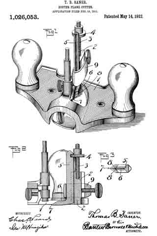
In the accompanying drawings, Figure 1 is a perspective view of a router plane with my improved cutter in place. Fig. 2 is a central vertical section. Fig. 3 is a plan view of the cutter foot, the shank being in section.
1 represents the main body of a router plane, the particular form of which is immaterial.
2 represents an upright cutter support or guide preferably provided with a screw thread 3 and an adjusting nut 4.
5 is the shank of the cutter.
6 is the foot of the cutter. The foot of the cutter projects forwardly and is pointed, as at 7. Leading back from the point 7 are two beveled inclines 8–8 on the top side of the foot, thereby forming two sharp cutting edges. The underside of the foot is, as shown in Fig. 2, pointed downwardly slightly, so that the toe end or point 7 will easily enter the wood to be cut. The guide 2 extends well down to the heel of the plane iron, as shown in sectional View Fig. 2; hence, the plane iron is given a powerful support throughout its length.
9 is a clamp, of any suitable form, for securing the cutter to the support 2. A part of the nut A projects into a notch at the back of the shank 5 of the cutter, so that as the nut is screwed up and down, the cutter will be correspondingly moved to vary the position of the point 7 of the cutter relatively to the sole of the plane.
As will be seen, in a cutter such as described, when the same is used in routing the material which is to be worked upon, an easy entrance into the material is guaranteed by the point 7. A double draw cut, which is the most effective in operation, is likewise secured by forming the point 7 substantially midway between the side edges of the foot 6. This arrangement has the further advantage of preventing any tendency toward deflecting that might otherwise exist. Again, when working across the grain, I have found by the use of this new type of cutter, all tendency to tear the wood is avoided. It is preferable that that part of the underside of the foot or toe immediately to the rear of the point 7 should be formed in a plane only slightly oblique to the sole of the plane body.
What I claim is:
In a cutter for a rabbet plane, a shank portion, a foot portion at the lower end of said shank portion and extending at an angle thereto, the toe of said foot portion being pointed, the opposite oblique sides of said foot being beveled on the top to form two oppositely arranged cutting edges, the underside of the toe immediately to the rear of the pointed cutting end being formed in a plane only slightly oblique to the sole of the plane body with which said cutter may be used whereby the two opposite side cutting edges and the pointed cutting end will lie in a substantially horizontal working plane.
THOMAS BENJAMIN SANER.
Witnesses:
EARL E. EATON,
H. W. EDWARDS.
Copies of this patent may be obtained for five cents each, by addressing the “Commissioner of Patents, Washington, D. C.”
_________________


