
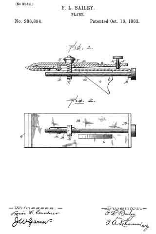
No. 286,894 – Plane (Fortune L. Bailey) (1883)
UNITED STATES PATENT OFFICE.
_________________
FORTUNE L. BAILEY, OF FREEPORT, INDIANA.
PLANE.
_________________
SPECIFICATION forming part of Letters Patent No. 286,894, dated October 16, 1883.
Application filed July 12, 1883. (No model.)
_________________
To all whom it may concern:
Be it known that I, F. L. BAILEY, of Freeport, in the county of Shelby and State of Indiana, have invented certain new and useful Improvements in Planes; and I do hereby declare the following to be a full, clear, and exact description of the invention, such as will enable others skilled in the art to which it pertains to make and use it, reference being had to the accompanying drawings, which form part of this specification.
My invention relates to an improveinent in planes; and it consists, first, in the combination of the bearing-plate having the adjusting-screw swiveled thereto, the slotted bit which is attached by means of a set-screw to the plate which bears against its top, and a screw-bolt which passes through both of the plates and the bit, and which has the adjusting-screw to pass through its lower end; second, in a bit having a nut passed through its outer end, and a set-screw passed through the nut, so as to have its lower end bear against the lower plate, and thus adjust the angle at which the bit shall set, as will be more fully described hereinafter.
The object of my invention is to provide an attachment for the bits of planes, whereby the bit can be adjusted back and forth and set it at any desired angle without having to remove the bit from the plane-stock.
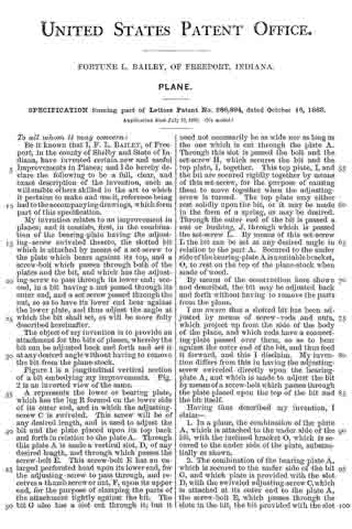
Figure 1 is a longitudinal vertical section of a bit embodying my improvements. Fig. 2 is an inverted view of the same.
A represents the lower or bearing plate, which has the lug B formed on the lower side of its outer end, and in which the adjusting-screw C is swiveled. This screw will be of any desired length, and is used to adjust the bit and the plate placed upon its top back, and forth in relation to the plate A. Through this plate A is made a vertical slot, D, of any desired length, and through which passes the screw-bolt E. This screw-bolt E has an enlarged perforated head upon its lower end, for the adjusting-screw to pass through, and receives a thumb screw or nut, F, upon its upper end, for the purpose of clamping the parts of the attachment tightly against the bit. The bit G also has a slot cut through it; but it need not necessarily be as wide nor as long as the one which is cut through the plate A. Through this slot is passed the bolt and the set-screw H, which secures the bit and the top plate, I, together. This top plate, I, and the bit are secured rigidly together by means of this set-screw, for the purpose of causing them to move together when the adjusting-screw is turned. The top plate may either rest solidly upon the bit, or it may be made in the form of a spring, as may be desired. Through the outer end of the bit is passed a nut or bushing, J, through which is passed the set-screw L. By means of this set-screw L the bit can be set at any desired angle in relation to the part A. Secured to the under side of the bearing-plate A is a suitable bracket, O, to rest on the top of the plane-stock when made of wood.
By means of the construction here shown and described, the bit may be adjusted back and forth without having to remove the parts from the plane.
I am aware that a slotted bit has been adjusted by means of screw-rods and nuts, which project up from the side of the body of the plane, and which rods have a connecting-plate passed over them, so as to bear against the outer end of the bit, and thus feed it forward, and this I disclaim. My invention differs from this in having the adjusting-screw swiveled directly upon the bearing-plate A, and which is made to adjust the bit by means of a screw-bolt which passes through the plate placed upon the top of the bit and the bit itself.
Having thus described my invention, I claim —
1. In a plane, the combination of the plate A, which is attached to the under side of the bit, with the inclined bracket O, which is secured to the under side of the plate, substantially as shown.
2. The combination of the bearing-plate A, which is secured to the under side of the bit G, and which plate is provided with the slot D, with the swiveled adjusting-screw C, which is attached at its outer end to the plate A, the screw-bolt E, which passes through the slots in the bit, the bit provided with the slot for the bolt to pass through, and the plate placed upon the bit, substantially as described.
3. The combination, with the bit, of a nut or bushing which is passed through its outer end, and the set-screw which is passed through the nut or bushing for the purpose of adjusting the inclination of the bit, substantially as specified.
4. The combination of the bearing-plate provided with a slot, the slotted bit, the set-screw, the plate which is placed upon the top of the bit, the screw-bolt which passes through both of the plates and the bit, the adjusting-screw for moving the bit back and forth, and the set-screw for regulating the angle at which the bit is placed, substantially as shown.
In testimony whereof I affix my signature in presence of two witnesses.
FORTUNE LEWIS BAILEY.
Witnesses:
MARCUS B. CHADWICK,
LEVI W. WHITE.