
No. 165,884 – Improvement In Bench-Planes (Hans Shogren) (1875)
UNITED STATES PATENT OFFICE.
_________________
HANS SHOGREN, OF PORTLAND, OREGON.
IMPROVEMENT IN BENCH-PLANES.
_________________
Specification forming part of Letters Patent No. 165,884, dated July 20, 1875; application filed March 19, 1875.
_________________
To all whom it may concern:
Be it known that I, HANS SHOGREN, of Portland, Oregon, and in the county of Multnomah of said State, have invented an Improvement in Bench-Planes, of which the following is a specification:
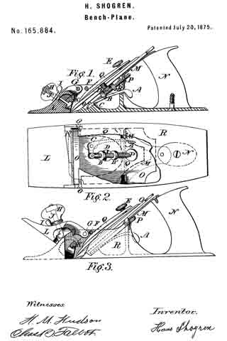
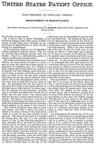
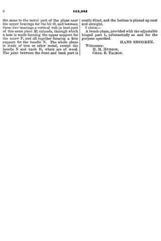
In the drawings, Figure 1 is a longitudinal section through or near the center. Fig. 2 is an inverted plan, looking upward from the bottom. Fig. 3 is a side elevation, partly in section, showing the movable front.
The nature and object of my invention are as follows: In many kinds of work it is necessary to bring the plane-bit O close against a glue-joint or projecting part of a rabbet, or other angular part rising above the surface to be planed, and with common planes this cannot be done, on account of the fore part of the plane in front of the bit, and after planing with them the end can only be finished with a chisel; but by the arrangement herein shown the work may be fully done by the plane itself. To accomplish this the fore part L of the plane R is hung on two screw-centers, G, situated one on either side of the plane opposite the opening for the shavings; and this part L is further provided with a knob, H, in which the nut and screw J are placed, and between H and L a small thumb wrench, I, is placed. The head of the screw J is a sort of eccentric or hook-shape, the sides of the screw-shaft being flattened in such manner that they ht the opening in the center of the wrench I.
Fig. 1 shows the plane when used as a common plane; and Fig. 2 shows the piece L closed in its place in front of the cross-rib K, which is a part of the back portion ofthe plane R. The head of the screw J is hooked. To change this, and put it in the position shown in Fig. 3, the following operation is gone through: First, the knob H, which carries the nut of the screw J, is turned so as to unscrew the nut, and while holding the knob H between the thumb and finger of one hand the other thumb turns the wrench I in such way as to still further unscrew the screw J, and this latter operation turns the screw half round, and disengages it from the cross-rib K. It may now be opened freely, as in the Fig. 3, or thrown entirely back on the top of the plane-iron, and in this position it may be used as now described. By looking at Fig. 2, and at the chip-opening in front of the bit O, an oblique line is seen crossing the under surface of the plane, and at its narrow end to run into the chip-opening. This is the joint between the front part L and the back part of the plane, so that if L were raised up or opened, as in Fig. 3, a portion of the chipway would be entirely open at the front, and half or more would have a narrow bearing in front of the plane-bit. In planing up to a projection this is so arranged that this part prevents the wood from lifting in front of the bit, and having planed to within a quarter of an inch or less of the object the plane is pushed sidewise, and in this way the chip is cut entirely out by the exposed part of the bit, the joint being so arranged that the bit is the foremost object on that side of the plane.
The next feature is the manner of fastening the bit O by means of the forked clamp Q, Fig. 2, screw E, and two pins, F, on theinside of the chip-opening, one on either side, so that the forked clamp Q passes under them somewhat after the manner of the wedge in a wooden plane, and to facilitate keeping Q in its place little hollows are formed on its upper surface, so that they will slightly engage with the pins F, and being so set under the pins F the screw E is tightened, and in this way the bit O is held firmly against its seat in the metal part R. The bit O is like those used in a common wood-plane, having at its back or under side the head of the clamp-screw D.
An arrangement for setting the bit O is as follows: A thumb-lever, A, projecting into the finger-opening in front of the handle N turning on a center, O, Fig. 2, carries a pitman-screw, P, in a joint of its shorter bent end. On the screw P are two nuts, B B’, which turn freely up or down, and are adjustable on the head of the clamp-screw D, and, being in proper adjustment, any movement of A raises the bit up or down. The center G is attached to the bottom of the plane, on the upper side, and beneath the bit O. A forked metal piece, M, Fig. 2, is fastened to the upper part of the handle N by a screw, and the corners or ends of the same to the metal part of the plane near the upper bearings for the bit O, and between these two bearings a vertical web (a bent part of this same piece M) extends, through which a hole is made forming the upper support for the screw P, and all together forming a firm support for the handle N. The whole plane is made of iron or other metal, except the handle N and knob H, which are of wood. The joint between the front and back part is neatly fitted, and the bottom is planed up neat and straight.
I claim —
A bench-plane, provided with the adjustable hinged part L, substantially as and for the purpose specified.
HANS SHOGREN.
Witnesses:
H. M. HUDSON,
CHAS. B. TALBOT.