
No. 383,234 – Bench-Plane (Thomas H. B. Millsap) (1888)
UNITED STATES PATENT OFFICE.
_________________
THOMAS H. B. MILLSAP, OF HARPER, KANSAS.
BENCH-PLANE.
_________________
SPECIFICATION forming part of Letters Patent No. 383,234, dated May 22, 1888.
Application filed April 13, 1887. Serial No. 234,678. (No model.)
_________________
To all whom it may concern:
Be it known that I, THOMAS H. B. MILLSAP, of Harper, in the county of Harper and State of Kansas, have invented a certain new and useful Improvement in Bench-Planes, of which the following is a full, clear, and exact description, reference being had to the accompanying drawings, forming part of this specification, and in which —
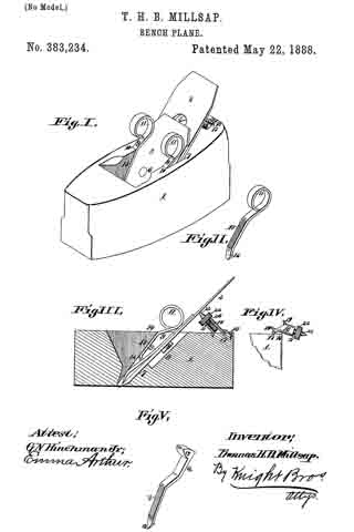
Fig. I is a perspective view of a bench-plane with my improved attachments, showing the action of the friction-spring side wedges in front and the pivoted adjustable abutment-clamp behind. Fig. II is a perspective view of one of the spring-wedges, showing its friction-surface for engagement with the abutment-shoulder of the stock. Fig. III is a longitudinal transverse section showing the bit-iron and the break-iron secured thereto, clamped intheirbcd in thestock by the spring-wedge and the adjustable abutting-clamp. Fig. IV is a detail side view, showing the adjustable abutment screw-clamp thrown back on its pivot in its inoperative position, and Fig. V is a modification of the friction spring adapted for use with heavy jointer-planes, &c. , having at its upper end an elongated bearing-surface that engages with the bit or break iron and a solid tapping-head, by striking which it is driven home to tighten the iron and back again to release it.
My invention relates to devices for adjusting and securing benchplane irons; and the invention consists in features of novelty hereinafter fully described, and pointed out in the claims.
Referring to the drawings, in which similar distinguishing figures indicate like parts in all the views, 1 represents the plane-stock, 2 the bit-iron, 3 the break-iron, which is adjustably secured to the bit-iron by the usual means, consisting of the coupling-screw 4, that works in the elongated slots 5 of the bit-iron and screws into the break-iron at 6.
7 is the inclined bed on which the bit-iron rests, and 8 is the elongated channe-groove in said bed to give adjustable room for the head of the screw 4.
9 are the friction-spring side wedges that conjointly press against the abutment-shoulders 10 of the stock and the bit or break iron. These springs are preferably made of good steel, and are looped around at top to provide circular handles 11 and curved upward onthe under side, both next the handles and the points 12, and thus form a semi-elliptic spring, which is flattened between said curves to present the friction surfaces 13 on their upper sides, which engage with the abutment-shoulders of the stock. The said friction-surfaces are roughened to give them grip-holds of the stock to prevent their slipping. (See Fig. I, II, and III.)
A rnodification of the springs is shown in Fig. V, and is intended for use with jointers and other large planes. The point, friction-surface, and arched curve are similar in these spring-wedge to those already described, but instead of the circular handle with which the former are provided, these are furnished at their upper ends with elongated bearing-surfaces 14 on their under sides that are seated on the bit or break iron, and they have also solid tapping heads 15, by striking which they are driven home to tighten the iron. and back again to loosen it.
16 is the adjustable abutting pedestal, which is connected by a pivot pin, 17, to the strap-hinge 18, that is secured to the stock. The pedestal is furnished with points 19 at its base, which points seat themselves in the stock under the pressure to which they are exposed, and with the re enforcement of the hinge by which the pedestal has pivotal connection with the stock is provided a firm vantage-ground, from which the abutting device connected with said pedestal can work.
20 is the thumb-screw whose screw-threaded end engages in the socket-screw 21 in the pedestal, and with its center point 23, which should be of hard tempered steel, and the said pedestal forms the abutting device to adjustably back the plane iron. The thumb-screw is operated by the friction disk 22, that is rigidly secured thereto.
The means of operating the device is as follows: The plane iron and break iron having been rightly adjusted and coupled in the usual manner and laid in their bed, the center point of the thumb-screw may be brought into close proximity with the back of the plane-iron by turning the friction-disk. The friction-spring side wedges are then driven down between the abutment-shoulders of the stock and the bit or break iron, and the abutting thumb-screw is turned to adjust the backing of the iron. The thumb-screw can be turned until its center point is exactly on a line with the inclined bed that the iron occupies in the stock, or it may, when preferred, be projected upward sufficiently to raise the upper end of theiron from its bed. In the latter position it furnishes a lively cutting-grip to the edge of the plane-iron, as the iron having play between the foot of the inclined bed to the point of contact of the abutment-screw gives a spring action to the edge not otherwise attainable. In either case, whether the iron is sprung above from its bed or not,the abutment screw, backing the iron at a point much higher than the usual backing against the inclined bed of the stock, furnishes a much firmer hold and efficient leverage on the iron than can be attained bythe shorter backing of the stock-bed. This feature is of special advantage in dressing cross-grained boards or timber, where the increased leverage that it gives to the hold of the iron prevents the trembling of the same.
Another, and it may be equally important, feature in the device is, that it leaves an open unobstructed vent for the escape of the shavings, which, with the wooden wedge hitherto used, that stretches across the whole slot of the stock, often becomes choked by the wedge, which blocks their ascent, and this causes the plane to choke.
The modification shown in Fig. V provides spring friction-wedges especially adapted for use in jointers and other heavy planes. It will be seen that except for the upper parts of the wedges they are counterparts of those shown in the other figures; but to adapt them to the heavy work which they are required to perform they are furnished at their upper ends with elongated bearing-surfaces on their under side, that are seated on the bit or break iron when the wedge is driven home, and, instead of the circular open head of the other wedges, have a solid head adapted to be tapped by a hammer or mallet when either driven home or released from its hold.
I claim as my invention —
1. In abench-plane, the combination, with the bit-iron and break-iron secured thereto, of spring-friction side wedges and pivoted abutment-pedestal having a center-pointed thumb screw adapted to adjust and secure said bit and break iron, substantially as set forth.
2. In a bench-plane, the combination, with the bit-iron, break-iron, and the stock having abutment-shoulders, of friction-wedges having spring-arches fiattened at their apices and adapted to engage with the abutment-shoulders of the stock, and an abutment-pedestal having a center-pointed thumb-screw, which, in conjunction with the said wedges, is adapted to adjust and hold the plane-irons to their place in the stock, substantially as set forth.
3. The combination, with the stock having abutment-shoulders and the bit and break iron, of a pivoted abutment-pedestal having a thumb screw adapted to engage the bit-iron, and spring-wedges engaging between the plane-irons and the abutment shoulders of the stock, said wedges being so arranged that there will be no intrusion on the chamber of the stock, to allow free vent for the shavings, substantially as set forth.
4. The combination, with the stock, bit and brake irons, of spring friction-wedges adapted to clamp the bit and break irons in front, a pivoted abutment-pedestal having a pointed projection adapted to engage the stock, anda pointed thumb-screw engaging in the end of said pedestal and adapted to adjust their backing and lengthen the lever-hold of said irons in the bed of the stock, and thereby steady their cutting action, substantially as set forth.
5. The combination, with the stock and its abutment-shoulders and the bit and break irons, of spring friction-wedges engaging between the front of the irons and the abutment-shoulders of the stock, leaving free vent between them for the escape of shavings, and a pivoted abutment-pedestal having a center-pointed rotary screw adjustable as an abutting support to the back of the irons, substantially as set forth.
THOMAS H. B. MILLSAP.
In presence of —
A. W. SKINNER,
F. W. HAWSER.