No. 289,332 – Joiner’s Plane (Henry B. Beach) (1883)
UNITED STATES PATENT OFFICE.
_________________
HENRY B. BEACH, OF MERIDEN, CONNECTICUT, ASSIGNOR TO
THE MERIDEN MALLEABLE IRON COMPANY, OF SAME PLACE.
JOINER’S PLANE.
_________________
SPECIFICATION forming part of Letters Patent No. 289,332, dated November 27, 1883.
Application filed September 10, 1883. (No model.)
_________________
To all whom it may concern:
Be it known that I, HENRY B. BEACH, of Meriden, in the county of New Haven and State of Connecticut, have invented a new Improvement in Joiners’ Planes; and I do hereby declare the following, when taken in connection with accompanying drawings and the letters of reference marked thereon, to be a full, clear, and exact description of the same, and which said drawings constitute part of this specification, and represent, in —
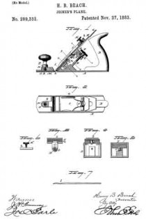
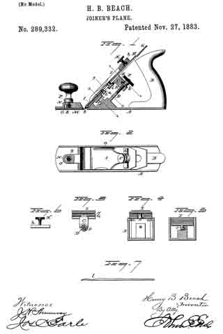
Figure 1, a sectional side view; Fig. 2, a top view; Fig. 3, a transverse section on line x x; Fig. 4, a transverse section on line y y; Fig. 5, a transverse section on line z z; Fig. 6, a transverse section through the clamping-bar h; Fig. 7, an edge view of the cap.
This invention relates to an improvement in that class of planes for joiners’ use in which the stock is made from cast metal, the object of the invention being a simple, ready, and positive adjustment and firmness of the plane-iron when once it is set in the required position; and the invention consists in the construction, as more fully hereinafter described, and particularly recited in the claims.
A represents the stock, made from cast-iron, fitted with the usual handle, B. Upon the inner surface of each side of the stock is a ledge, a, inclined in a line from the mouth, according to the pitch required for the plane-iron. These ledges form supports for the bed C, and on the upper surface of which the bed rests — that is to say, the bed lies upon these inclines. Below these inclined bearings a, and centrally between the two sides, a screw-stud, D. is set in a plane parallel with the inclines both vertically and horizontally, as seen in Fig. 1. From the under side of the bed a lug, E, extends downward, with an opening through it corresponding to the screw-stud D, and so as to pass freely over the stud.
F is a nut fitted to the screw-stud, and carrying a collar, b. The lug is recessed transversely to form a slot, d, to receive the collar b of the nut, and so that in placing the bed in its position the nut is first set into engagement with the slot d, then the bed moved down to carry the lug over the screw-stud, and so as to permit the nut to engage the screw; then turning the screw in one direction will move the bed downward, and in the reverse will draw it upward.
On the bed C the plane-iron G is placed, and over this the clamp H, and then upon that the clamp I, which is secured by a set-screw, K. The arrangement of the clamp whereby the plane-iron is secured to the bed may be any of the usual constructions.
As here represented, a headed stud, L, attached to the clamp I, passes through beneath the cap and iron and engages a slot in the bed below, so as to form a fulcrum for the clamp. Then the point of the clarnp bears upon the iron, the power being applied through the screw K to force the point into its clamping position — a usual and well-known construction. The bed is held down at its lower end by an L-shaped lug, e, engaging a corresponding L-shaped flange, f, on the stock. (See Figs. 1 and 5.)
In the usual construction of this class of clamps the screw is inade to bear at a central point and over a comparatively small surface. Unless the corresponding surfaces of the bed and plane-iron make a perfect fit between the two, the iron is easily thrown out of adjustment. To increase this bearing-surface of the adjusting-screw, I arrange a bar, h, in a slot transversely across on the under side of the head of the clamp, and it should be in length nearly the width of the plane-iron. This is engaged with the set-screw by upsetting the screw upon the under side of the bar, as seen in Figs. 1 and 6, but so as to leave the screw free to turn in the bar; hence by turning the screw in one direction the bar will be drawn into the slot, and turned in the opposite direction will be forced downward. This transverse bar affords a long surface of bearing upon the plane-iron, and so that the force of the screw is applied to that entire surface; hence so broad or extended a bearing upon the plane-iron is attained as to prevent the possibility of accidental displacement. In this class of planes in which a cap is employed in connection with the plane-iron a ditliculty is experienced in properly fitting the edge of the cap to the surface of the plane-iron, or to bring it into a firm and close bearing entirely across the face of the plane-iron, and if it be not thus perfectly fitted shavings will work between the two and inconvenience the workman. In the usual construction of cap the edge is drawn down thin and turned toward the plane-iron, so as to raise that portion of the cap back of its edge from the iron; then the set-screw i applied is relied upon to draw the cap properly onto the iron; but this set-screw is necessarily so far from the foot that unless both the iron and the cap are perfect in their construction the requisite fit cannot be attained. To overcome this difficulty I reduce the cap in thickness a little above the foot, as at l, Figs. 1 and 7 , so as to weaken the cap at that point. Then the screw is applied in the usual manner. The clamp bears upon the cap at this reduced point, as seen at Fig. 1, and applies a pressure which, because of the reduction in thickness of the cap, will cause the foot of the cap to spring into the shape to fit closely and entirely across the face of the plane-iron. This construction permits the cap to be drawn into close contact with the iron around the set-screw, as shown, thus making a firm connection between the cap and iron, so that dis-
placement of the cap is impossible, and the clamp serves to bring the foot of the cap into its proper relation to the face of the iron; and this construction also enables me to make the cap of thicker material than can be done where there is no such reduction in thickness, for without the reduction there must be sufficient spring in the cap to permit the screw which holds it in place to draw the cap down to the iron; but this reduction in thickness requires less power upon the screw, and also enables the clamp to properly hold the cap in place.
In adjustable mouth planes — that is, planes which have the bottom fore end adjustable, so as to take the forward edge of the mouth nearer to or farther from the iron, as occasion may require – a difliculty is experienced from the fact that the adjustable portion is liable to be forced against or into contact with the cutting-edge of the iron, consequently drilling the plane. To obviate this difficulty I construct the adjustable part M so as to be moved toward or from the mouth in the usual manner, and upon its upper surface form a socket, N, fitted with a female screw, the socket arranged to work in a longitudinal recess, O, in the stock, the recess being constructed with relation to the socket N so that the rear side of the socket will strike the rear end of the slot O just before the adjustable piece M will reach the edge of the iron, and through a slot, P, into the recess a set-screw, R, passes into the socket N to bind the adjustable part in any position to which it may be set.
The set-screw itself may form the stop, instead of the socket — that is, the slot P, through which the set-screw passes, may be of such length that the body of the screw will strike the forward end of the slot just before the adjustable piece M will reach the edge of the iron, it only being essential to this part of my invention that there shall be a stop to thus arrest the adjustable piece M.
I claim —
1. In a metal plane, the combination of the stock, constructed with inclined lugs a upon its two sides to support the bed, the bed C, arranged to ride upon said lugs, the screw-stud D, fixed in the stock and parallel with the plane of the bed, a lug, E, extending from the bed and arranged to work over said screw-stud, said lug constructed with a transverse recess, d, the nut F, constructed with the collar b, corresponding to the said recess d, and mechanism, substantially such as described, to clamp the iron upon the bed, all substantially as specified.
2. In a metal plane substantially such as described, the clamp I, by which the plane-iron is secured to the bed, combined with a transverse bar, h, and adjusting-screw K, substantially as specified.
3. In a joiner’s plane substantially such as described, the cap H, having its thickness reduced transversely near its foot, substantially as and for the purpose described.
4. In a joiner’s plane, the combination of a bed made adjustable, a plane-iron upon said bed, a clamp in connection with said bed, the cap H, reduced in thickness transversely near its foot, said clamp arranged to bear upon said cap near its reduced thickness, and mechanism, substantially such as described, to force said clamp to thus bear upon the cap, substantially as specified.
HENRY B. BEACH.
Witnesses:
E. A. MERRIMAN,
CHAS. WM. MANN.

