
No. 122,339 – Improvement In Bench-Planes (Charles E. Torrance) (1872)
UNITED STATES PATENT OFFICE.
_________________
CHARLES E. TORRANCE, OF HOLYOKE, MASSACHUSETTS.
IMPROVEMENT IN BENCH-PLANES.
_________________
Specification forming part of Letters Patent No. 122,339, dated January 2, 1872.
_________________
To all whom it may concern:
I, CHARLES E. TORRANCE, of Holyoke, Hampden county, Commonwealth of Massachusetts, have invented certain Improvements in Bench-Planes, of which the following is a specification:
My invention relates to the combination, with the bed piece and cutters of a metal plane, of two spurs or projections proceeding from the inner sides of the bed piece in front of the cap piece of the plane-iron, for the purpose of acting as a fulcrum; of a surface inclining from the rear side of the plane-iron within the bed piece tor the purpose of acting as a bearing for a wedge; and of a wedge extending across the plane-iron, also within the bed piece, and for the purpose of being inserted between the inclined surface behind the plane-iron and the plane-iron itself, to enable the size ofthe shaving to be regulated by the adjustment of the plane and cap-irons within the mouth of the plane; the object of my invention being to enable the construction of metal planes to be so simplified that when the bed piece is cast the addition of a wooden wedge is all that is needed to enable the cutters, when inserted, to be quickly and firmly adjusted to any bite.
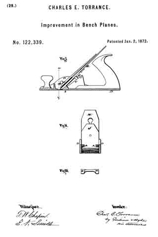
In the drawing, Fig. 1 is a side sectional view; Fig. II, a vertical cross-section on the line x y; and Fig. III, a view of the wedge.
D is the bed piece, cast in one piece with the projections A A opposite each other at points upon the inner sides of the bed piece, so that the cap-iron J bears against them near the upper end of its curve, and when the pressure needed for the most advantageous working of the plane-iron H can be obtained by the insertion or withdrawal of the wedge B. Cast also upon the bed piece are the surfaces C C, raised from the inner sides, as shown in Fig. I, and extending sufficiently far to enable the wedge to be accessible for adjustment. The sides of these upon which the wedge B slides are deflected from the inner side of the plane-iron to assist the action of the wedge. The stock in the base of the bed piece is made thicker on the inner face of the mouth to form the bearing b, which rises in contact with the inner surface of the plane-iron to hold the same when the cap-iron is compressed by the insertion of the wedge, and the point of contact between the bearing b and plane-iron H being below the projections A A the insertion of the wedge acts to compress the toes of the two irons H and J, and vary their points of contact, while both are securely braced against all possibility of buckling or rising from their bed. The wedge B, which I prefer to make of wood, as being lighter than metal and less apt to slip or slide upon a metal surface, is formed as shown in Fig. III, so as to, for convenience, constitute two wedges connected by a handle easily grasped.
There is nothing new in my plane in either the cutters, handle, or the knob; but by my improvements the cost of manufacture is reduced more than one-half, and a simple and effective tool is made that cannot get out of order, and having for its only detachable parts the wedge and the irons.
New having described my invention, what I claim as new, and desire to secure by Letters Patent, is —
In combination with the irons J and H, and cast-iron bed-plate D with its bearing surfaces c c and b, the projections A A cast upon the bed-plate and wedge B, the parts being constructed and arranged as shown and described.
CHARLES E. TORRANCE.
Witnesses:
R. F. HYDE,
E. N. SMITH.