No. 81,425 – Improvement In Planes (F. Smith And I. Carpenter) (1868)

United States Patent Office.
F. SMITH AND I. CARPENTER, OF LANCASTER, PENNSYLVANIA.
Letters Patent No. 81,425, dated August 25, 1868.
_________________
IMPROVEMENT IN PLANES.
_________________
The Schedule referred to in these Letters Patent and making part of the same.
_________________
TO ALL WHOM IT MAY CONCERN:
Be it known that we, F. SMITH and I. CARPENTER, of Lancaster, in the county of Lancaster, and State of Pennsylvania, have invented a new and useful Improvement in Joiners’ Planes; and we do hereby declare that the following is a full, clear, and exact description thereof, which will enable those skilled in the art to make and use the same, reference being had to the accompanying drawings, forming part of this specification.
The nature of our invention relates to improvements in joiners’ planes, whereby it is designed to render the stocks less liable to warp, to regulate the weight of the same, to provide for a more perfect delivery of the shaving, adjusting the some to be used as a single or a double plane, and adjusting the mouth, so as to govern the width of the same for the passage of the shaving.
And it consists in constructing the stock partly of iron, substituting, for the tapered notches of wooden stocks for holding the tightening-wedges, set-screws for holding the wedge, which is made of metal, and provided with an additional tightening-screw in its upper end, which works against the face ofthe plane-bit, or into a swivel-nut which slides in the slots of plane-bits, as ordinarily constructed, and providing a wooden wedge at the back side ofthe plane-bit, as will be more fully described on reference to the accompanying drawings, wherein —
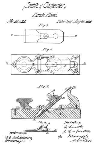
Figure 1 represents a plan view of our improved plane.
Figure 2, a central section ofthe same on the line x x of fig. 1.
Figure 3, a plan view of a part of our improvement applied to plane-bits, having the ordinary slot in the same; and
Figure 4 a section on the line y y of fig. 3.
Similar letters of reference indicate corresponding parts.
A represents the wood part of the stock, and B the iron portion of the same, which are secured together by the screws d d.
The part B may-be made of cast iron, and of different thicknesses, as may be desired to govern the weight of the plane.
The handle and knob may be secured to the part B in suitable sockets provided for them by the screws d d.
The part B is provided with lugs, a1 a1, through which set-screws, a2 a2, are arranged to hold the cap.
C represents a metal cap or wedge, provided with a set-screw, b, by which it may be, if desired, raised at its upper end from the bit D.
The said cap is provided with a raised portion, C’, in advance of the set-screw b, which rises by a gentle curve from the wedge portion of the same, so as to prevent the shavings from clogging against the screw.
When a plane-bit is used without a slot, as in figs. 1 and 2, we use a set-screw arranged as therein shown, but to adapt our improved tightening-wedge to plane-bits of the old construction, having the slot for set-screws as ordinarily constructed, we attach, to the ends of the set-screws, swivel-nuts, e, having slots in two edges of the same, which admit it to slide within the slot in the plane-bit, by taking the edges of the bit forming the side walls of the slot in the latter into the slots in the nut, the nut being of the proper size to be admitted through the enlarged portion of the slot in the plane-bit.
E represents a wedge, which may be made of wood or metal, and arranged in the bottom of the mouth of the stock under the plane-bit, and held there by the set-screw e1 passing through a slot in the said wedge, whereby it may be adjusted within the mouth ofthe stock.
The face of the wedge next the plane-bit is provided with a recess, e2, to admit the nut e of the set-screw.
The under side of the upper end of the metallic wedge C is provided with a recess, f, (see fig. 4,) when the nut e is used.
By the use of our improved wedge, the same plane-bit may be used for a double or single bit.
When used as a single bit, it may be applied as shown in fig. 2, and when used as a double bit, the set-screws a2 may be withdrawn, so that the wedge may be moved down sufficiently near to the edge of the bit to serve the purpose of a double bit.
By adjusting the upper end of the wedge by a set-screw, b, the width of the mouth may be adjusted to suit the different requirements of different kinds of work, or of different kinds of wood, or may be made of uniform width from bottom to top.
The same may be also adjusted by the wedge E to some extent, but the more important function of the wedge E is to govern the width of the throat at the cutting-edge of the bit, as at k, as will be readily understood.
In adjusting the wedge to the bit, when constructed as shown in figs. 3 and 4, the lower end of the wedge is placed at the right position with reference to the cutting-edge of the bit, and the thumb-screw turned to the left until the upper end of the wedge is screwed tightly to the bit. They are then inserted in the stock, the set-screws a2 adjusted to their right positions, when the set-screw b is turned in the opposite direction, and the wedge forced out against the set-screws a2.
The metallic part, B, of our stock may be taken off from a worn-out wood stock, and readily applied to a new one, or old plane-stocks of ordinary construction may be readily fitted to be attached to it.
We claim as new, and desire to secure by Letters Patent —
1. The adjustable cap, provided with the guard in front of the set-screw b, substantially as and for the purpose described.
2. The set-screws a2 in the lugs a1, arranged to clamp upon the adjustable wedge C, as herein shown and described for the purpose specified.
F. SMITH,
I. CARPENTER.
Witnesses:
P. G. EBERMAN,
F. R. GRUGER.


