
No. 392,425 – Carpenter’s Plane (James Hartness And John J. Tower) (1888)
UNITED STATES PATENT OFFICE.
_________________
JAMES HARTNESS, OF TORRINGTON, CONNECTICUT, AND JOHN J. TOWER,
OF BROOKLYN, NEW YORK; SAID HARTNESS ASSIGNOR TO SAID TOWER.
CARPENTER’S PLANE.
_________________
SPECIFICATION forming part of Letters Patent No. 392,425, dated November 6, 1888.
Application filed January 14, 1888. Serial No. 260,769. (No model.)
_________________
To all whom it may concern:
Be it known that we, JAMES HARTNESS, of Torrington, in the county of Litchfield and State of Connecticut, and JOHN J. TOWER, of the city of Brooklyn, and State of New York, have invented an Improvement in Carpenters’ Planes, of which the following is a specification.
Carpenters’ planes have been made in which the cutter-iron is held within the stock and is adjusted to cut thicker or thinner shavings by the action of a screw or a lever, and this cutter-iron is clamped to its place by a lever having hooks or lugs that catch behind the portion of the stock or movable cradle upon which the cutter-iron rests. A plane of this character is represented in Letters Patent No. 126,519, granted May 7, 1872, to O. R. Chaplin.
Our present improvement is made for preventing a difliculty that has been experienced in this character of plane-namely, that the cap-iron cannot easily be adjusted and held in the proper position to the cutting-edge of the cutter-iron, because the cap-iron has been attached to the clamp and is moved by and with the clamp when the same is placed upon the cutter-iron, and with planes, especially those having a wooden face, the cutting-edge is within the mortise and cannot be easily seen, and hence the cap-iron may slip down and injure the edge of the cutter, or it may be too far away from the edge of the cutter, and hence not act in the desired manner to break the shavings transversely and prevent the wood splitting.
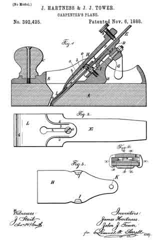
In the drawings, Figure 1 is a longitudinal section of our improved plane. Fig. 2 is a I detached view of the cap-iron and cutter. Fig. 3 is a separate view of the clamp. Fig. 4 is a section at the line x x, Fig. 1.
The face of the plane and the stock are of any desired character; but our improvement is especially available when the face A of the plane is of wood, to which the metal stock B is attached, having a handle, C, and the inclined bearing D for the cutter-iron E, and this inclined bearing D, is capable of being moved up and down by the action of a screw or lever. We have represented a screw-segment, F, and lever G for adjusting the cutter-iron, as in the aforesaid patent, and the clamp H is made slightly concave upon the under side and provided with hooks or lugs I, that hook behind the inclined bearing D by moving the clamp H down over the cutter-iron, so that the hooks pass along under the bearing D, and there is a screw, K, that acts against the face of the cutter-iron at the upper end of the clamp-lever to force the lower end of such clamp against the capiron L and cutter-iron E.
Instead of connecting the cap-iron L to the clamp H by pins or otherwise, as in said patent, we make the cap-iron L with a longitudinal slot, 2, and with a narrower upper portion, 3, within which such slot is formed, and the lower end, 4, of the cap iron L is of a width corresponding to the width of the cutter-iron E, and the under side of the cap-iron L is slightly concave, as usual in cap-irons, and we make use of a screw, O, passing through the slot 2, for fastening the cap-iron L firmly to the cutter-iron E, and the slot 2 allows for the adjustment of the cap-iron L to bring the end 4 to the proper distance from the cutting-edge of the cutter-iron E. This is done after the cutter has been sharpened and before it is placed in the plane-stock, and this operation in itself is thesame as that which is performed in ordinary carpenters’ planes, and it is usually preferred by carpenters to be able to adjust the cap-iron to the cutter in this manner; but an ordinary cutter-iron and cap-iron are not adapted to the stock and clamp with which our improvement is used, because the hooks I render it necessary to make the cutter-iron narrower at the upper part than in the lower part, and to adapt the cap-iron to the cutter-iron we make the cap-iron narrower, as shown at 3, so that it may extend upwardly the desired distance on the cutter-iron and not be in the way of the hooks I, and we place the screw O with the head above the cap-iron, so that the cutter-iron may rest down flat upon the inclined bearing D; and we may stiffen the upper portion of the cap-iron L by the ribs 5, that are bent up at the edges of the narrower portion, 3, of such cap-iron. The clamp H, being slightly concave on its under side, is adapted to set over the screw o and narrow portion of the cap-iron.
In the ordinary plane-irons the cutter-iron is slotted longitudinally and the screw passes through the slot in the cutter-iron into the cap-iron. This cannot be used in the character of plane upon which our improvement is made, because the screw in that case comes at the back or under side of the cutter-iron.
The ribs 5 upon the cap-iron stiffen the same sufficiently to insure the proper contact of the end 4 of such cap-iron against the surface of the cutter-iron, and the pressure is also increased by the lower end of the clamp-lever H, that is pressed upon the same to hold the cutter in place by the action of the screw K.
The adjustment of the cutter to cut the thicker or thinner shavings is effected in the usual manner without varying the distance between the end it of the cap-iron and the cutting-edge of the cutter-iron E.
We claim as our invention —
1. The combination, with the plane-stock and the inclined bearing D, of the cutter-iron E, the slotted cap-iron L, a screw passing through the slot and attaching the same to the cutter-iron, and the clamp H, made concave to set over the screw and narrow portion of the cap-iron, having hooks I, that catch behind the inclined bearing D, and the clamping-screw K at the upper end of the clamp H for pressing the lower end of the clamp upon the cap-iron and holding the same and the cutter in place, substantially as set forth.
2. The cap-iron L, having a slot, 2, and the ribs 5 at the edges of the narrower portion, 3, of said cap-iron, in combination with the cutter-iron E and the screw O, for connecting the cap-iron to the cutter-iron, and the clamp H, having hooks I, and the screw K, substantially as set forth.
3. The combination, with the cutter-iron E, of the cap-iron L, corresponding in width at its lower end to the width of the cutter and the upper portion, 3, being narrower and provided with a slot, 2, the screw O, for attaching the cap iron to the cutter, the clamp H, having hooks I, and the screw K, and the inclined bearing D and plane-stock, substantially as set forth.
Signed by us this 29th day of December, 1887.
JAMES HARTNESS.
JOHN J. TOWER.
Witnesses:
JOHN W. BROOKS,
W. H. COLE.