No. 763,721 – Plane-Iron-Adjusting Device (John W. Carleton And George E. Trask) (1904)

[paiddownloads id=”605″]763721


UNITED STATES PATENT OFFICE.

_________________

JOHN W. CARLETON AND GEORGE E. TRASK, OF NEW BRITAIN, CONNECTICUT, ASSIGNORS TO
UNION MANUFACTURING COMPANY, OF NEW BRITAIN, CONNECTICUT, A CORPORATION.

PLANE-IRON-ADJUSTING DEVICE.

_________________

SPECIFICATION forming part of Letters Patent No. 763,721, dated June 28, 1904.
Application filed October 26, 1903. Serial No. 178,477. (No model.)

_________________

To all whom it may concern:

Be it known that we, JOHN W. CARLETON and GEORGE E. TRASK, citizens of the United States, residing at New Britain, in the county of Hartford and State of Connecticut, have invented certain new and useful Improvements in Plane-Iron-Adjusting Devices, of which the following is a specification.

Our invention relates to improvements in plane-iron-adjusting devices; and the object of our improvement is convenience and efficiency in use.

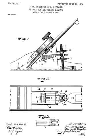
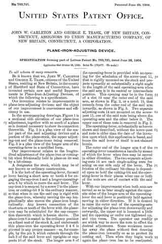
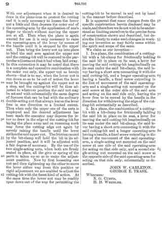
In the accompanying drawings, Figure 1 is a sectional side elevation of our plane-iron adjustment, together with so much of a plane as is deemed necessary to show its connection therewith. Fig. 2 is a plan view of the major part of the said adjusting devices and a portion of the plane-stock, the upper adjusting-nut and the plane-irons being removed. Fig. 3 is a plan view of the longer arm of the operating-lever in a modified form.

Our improvement relates to the longitudinal adjustment of the plane-iron or cutting-bit when frictionally held in place on its seat by a bit-clamp.

A designates the stock, which may be of any known or ordinary construction.

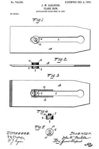
3 is the hub of the operating-lever, the said lever having a short arm or tooth 4 for engaging the cap-iron 5 and a longer operating-arm 6 by which to move the said lever. The cap-iron 5 is secured by a screw 7 to the plane-iron or cutting-bit 8 in the ordinary manner, so that when in use the said cap is rigid with the plane-iron, whereby moving the cap longitudinally also moves the plane-iron longitudinally. Any known connection of the short arm or tooth of the lever with the plane-iron may be substituted for the cap connection therewith which is herein shown. The plane-iron 8 is seated in the ordinary position on a fixed seat of the stock A, and underneath this plane-iron the operating-lever 3 4 6 is pivoted in any proper manner — as, for example, by the pin 9, which extends through the hub 3 of the said lever and uprights or supports 10 of the stock. The longer arm 6 of the operating-lever is provided with an opening for the admission of the screw-post 11 that is rigidly mounted on the stock and projects upwardly at substantially a right angle to the length of the said operating-arm when the said arm is in its central or intermediate position. This opening may be in the form of a slot 12 near the outer end of the said arm, as shown in Fig. 2, or a notch 13, that extends from the outer end of the said arm inwardly, as shown in Fig. 3. Two separate adjusting-nuts 14 are mounted on the screw-post 11, one of the said nuts being above the operating-arm and the other below it. The upper one of these nuts is removed in Fig. 2.

The operating-lever, substantially as herein shown and described, without the screw-post and nuts is older than the date of the invention upon which this application is based, and hence the said lever of itself is not claimed herein.

The outer end of the longer arm 6 of the operating-lever constitutes a handle by means of which the lever when free may be moved in either direction. The two separate adjusting-nuts 14 are each single-acting nuts for acting on one side only of the lever. The friction of the ordinary bit-clamp is depended upon to hold the cutting-bit and the operating-lever in their places when one or both of the nuts are out of contact with the said lever.

With our improvement when both nuts are turned so as to bear snugly against the opposite sides of the longer arm of the operating-lever the said lever is positively held against moving in either direction. If it is desired to raise the outer end of the operating-arm for adjusting the plane-iron downwardly and outwardly, the upper nut is loosened a little and the opposing or under nut tightened up, and vice versa. The operator can readily see which way to move the nuts to effect the desired adjustment. Some workmen never lay away the plane without first drawing the plane-iron inwardly so as to protect its cutting end. Then when they begin work again the plane-iron has to be readjusted. With our adjustment when it is desired to draw in the plane-iron to protect the cutting end it is only necessary to loosen the lower nut a little and then depress the outer end of the operating-arm by the application of one’s finger or thumb without moving the upper nut at all. Then when the plane is again wanted for use it. is only necessary to raise the operating-arm of the lever by means of the handle until it is stopped by the upper nut. Then bring the lower nut up into place to bind the said arm against the upper nut and the cutting-bit will be restored to the particular adjustment that it had when laid away. In this connection it may be noted that there is a complete and operative combination with the outer nut only, the upper nut as herein shown-that is to say, when the lower nut is run down so as to be out of action the lever may be brought up against the upper nut as a stop, and the cutting-bit will be thus adjusted to whatever position the said nut may be set and with substantially the same degree of fineness that can be had with the ordinary double-acting nut that always leaves the lever free in one direction to a limited extent. Thus when only the upper one of the nuts is employed and the desired adjustment has been made the operator may depress the lever to draw in the edge of the cutting-bit for laying the plane away and on resuming work may force the cutting edge out again by merely raising the handle until the lever strikes the said upper nut. The friction caused by the bit-clamp will hold the bit in its adjusted positien, and it will be adjusted with a fair degree of accuracy. By the use of the two single-acting nuts, when both are firmly seated in place, all the give or spring of the parts is taken up so as to make the adjustment positive. Now by first loosening one nut and then tightening up the other to move the lever either way from this positive or rigid adjustment we are enabled to adjust the cutting-bit with the iinest kind of action. At the same time the lower nut may be readily spun down out of the way for permitting the cutting-bit to be moved in and out by hand in the manner before described.

It is apparent that some changes from the specific construction herein disclosed may be made, and therefore we do not wish to be understood as limiting ourselves to the precise form of construction shown and described, but desire the liberty to make such changes in working our invention as may fairly come within the spirit and scope of the same.

We claim as our invention —

1. In a plane, the combination of a cutting-bit with a bit-clamp for frictionally holding the said bit in place on its seat, a lever for moving the said cutting-bit longitudinally on its seat under the said bit-clamp, the said lever having a short arm connecting it with the said cutting-bit, and a longer operating-arm having a handle, a fixed screw extending in the line of movement of the said operating-arm and a single-acting nut mounted on the said screw at the outer side of the said arm and acting on the said side only, leaving the lever free to be moved by the handle in the direction for withdrawing the edge of the cutting-bit substantially as described.

2. In a plane, the combination of a cutting-bit with a bit-clamp for frictionally holding the said bit in place on its seat, a lever for moving the said cutting-bit longitudinally on its seat under the said bit-clamp, the said lever having a short arm connecting it with the said cutting-bit and a longer operating-arm having a handle, a fixed screw extending in the line of the movement of the said operating-arm, a single-acting nut mounted on the said screw at one side of the said operating-arm for acting on that side only, and a second single-acting nut mounted on the said screw at the opposite side of the said operating-arm for acting on that side only, substantially as described.

JOHN W. CARLETON.
GEORGE E. TRASK.

Witnesses:
N. G. CURTIS,
H. H. WHEELER.

No. 746,286 – Plane-Iron (John W. Carleton) (1903)

[paiddownloads id=”594″]746286


UNITED STATES PATENT OFFICE.

_________________

JOHN W. CARLETON, OF NEW BRITAIN, CONNECTICUT, ASSIGNOR TO
UNION MANUFACTURING COMPANY, OF NEW BRITAIN, CONNECTICUT,
A CORPORATION OF CONNECTICUT.

PLANE-IRON.

_________________

SPECIFICATION forming part of Letters Patent No. 746,286, dated December 8, 1903.
Application filed September 19, 1903. Serial No. 173,821. (No model.)

_________________

To all whom it may concern:

Be it known that I, JOHN W. CARLETON, a citizen of the United States, residing at New Britain, in the county of Hartford and State of Connecticut, have invented certain new useful Improvements in Plane-Irons, of which the following is a specification.

My invention relates to improvements in plane irons or cutters; and the object of my improvement is to facilitate securing the bit-adjusting bolt to the body of the cutting-bit or plane-iron.

In the accompanying drawings, Figure 1 is a plan view of my plane-iron. Fig. 2 is a side elevation of the same. Fig. 3 is a reverse plan view of the same. Fig. 4 is a detached side elevation of the adjusting-bolt with the nut removed. Fig. 5 is a plan view of the same.

A designates the cutting-bit, having the usual longitudinal slot 6, within the lower end of which is the bolt 7, by which to connect the said cutting-bit with any ordinary devices for adjusting the said bit longitudinally. This bolt has its head 8 projecting from the under side of the bit and is provided with a slot 9 to receive a projection of the lever or other device for adjusting the bit longitudinally. A portion of the head is slabbed off on opposite sides, as at 10, Figs. 4: and 5, to let the said bolt-head into the slot 6 of the bit, with the said slabbed-off portions acting in connection with the sides of the slot to prevent the said bolt from rotating within the said slot. The end or body of the bolt 7 is screw-threaded and receives a nut 11, which rests upon smooth surfaces on the upper broad side of the cutting-bit or plane-iron and by which nut the said bolt may be adjustably secured at any desired position in the lower end of the said slot. This nut is provided with a screw-driver slot 12 to facilitate securing it in place. As shown, the periphery of the said nut is also provided with a knurled surface to facilitate turning the nut with one’s fingers.

Upon each side of the slot 6, from its lower end upwardly a part of the length of the said slot, there is formed a roughened face 13, Fig. 3, which may be simply a series of alternate fine grooves and ridges extending from the edges of the slot 6 outwardly about the same distance that the bolt-head 8 projects beyond the said edges. These roughened surfaces come under the non-rotating head of the bolt, which is drawn firmly against them by tightening up the nut. This nut bears on smooth surfaces, so that it turns smoothly when it is rotated to draw the bolt-head against the roughened surfaces on the opposite broad side of the cutting-bit, whereby the bolt can be readily and firmly secured in its adjusted position without applying excessive power to the nut. This bolt is designed to be set in the proper position to connect with the longitudinally-adjusting devices when the lower end of the cutting-bit is within its proper range of movement relatively to the throat of the plane-stock. When the cutting-bit is shortened up by wear and repeated grinding, so as not to have the proper range of movement relatively to the throat, the bolt can be readjusted accordingly.

I claim as my invention —

The herein-described cutting-bit having the central longitudinal slot with adjacent smooth surfaces on one broad side of the said bit, and roughened surfaces adjacent to the said slot on the opposite broad side of the said bit and the non-rotating bolt fitted to the said slot and provided with means for being connected with the longitudinally-adjusting devices for the said bit, the said bolt being arranged in the said slot with its head bearing on the said roughened surfaces on one broad side of the said bit and the nut bearing on the opposite broad side of the said bit.

JOHN W. CARLETON.

Witnesses:
JAMES SHEPARD,
SHEFFIELD H. CLARKE.

No. 746,285 – Plane (John W. Carleton And George E. Trask) (1903)

[paiddownloads id=”593″]746285


UNITED STATES PATENT OFFICE.

_________________

JOHN W. CARLETON AND GEORGE E. TRASK, OF NEW BRITAIN, CONNECTICUT,
ASSIGNORS TO THE UNION MANUFACTURING COMPANY, OF NEW BRITAIN, CONNECTICUT.

PLANE.

_________________

SPECIFICATION forming part of Letters Patent No. 746,285, dated December 8, 1903.
Application filed August 1, 1903. Serial No. 167,897. (No model.)

_________________

To all whom it may concern:

Be it known that we, JOHN W. CARLETON and GEORGE E. TRASK, citizens of the United States, residing at New Britain, in the county of Hartford and State of Connecticut, have invented certain new and useful Improvements in Planes, of which the following is a specification.

Our invention relates to improvements in planes; and the objects of our improvement are simplicity and economy in construction and convenience and efficiency in operation.

In the accompanying drawings, Figure 1 is side elevation of our plane. Fig. 2 is a central longitudinal section of the same, partly in elevation. Fig. 3 is a plan view of the same with the holding-cap, cap-iron, and cutting-bit removed. Fig. 4 is a side elevation of the middle portion of the iron frame of the stock. Fig. 5 is a side elevation of our plane when made with an iron stock without the wooden body. Fig. 6 is a sectional view of the same on the line x x of Fig. 5 when viewed in the direction of the dart in the said Fig. 5, the cutter being removed. Fig. 7 is a sectional side elevation of the middle portion of the stock and the adjusting-levers. Figs. 8 and 9 are plan and reverse plan views, respectively, of the cutting-bit with attached cap-iron and adjusting-nut, the same being adapted for use in both of the constructions herein shown. Fig. 10 is a plan view of the holding-cap and its screw.

A designates the wooden body, and B the iron frame, the said two parts together forming the stock of the plane. If desired, the wooden body A of the stock may be provided with a metal sole 5; but this is not essential. The frame B has an end plate 6 at its forward end provided with a hole for receiving the holding-screw 7 and also with a seat for the knob 8, the said seat being centrally perforated to receive the screw 9, that serves the double function of securing the said knob in place and of assisting to secure the said frame to the wooden body of the stock. At the rear end of the plate 6 there is a cross-rib 10, and extending rearwardly from the ends of the said cross-rib at opposite sides of the stock are the two side pieces 11 of the iron frame B, with the holding-lugs 12 on their confronting inner faces over the opening for the throat 13 of the stock. These side pieces 11 extend parallel to each other along the sides of the stock to a point in the rear of the middle of the length of the stock and then turn inwardly toward each other to the handle-seat 14 on the rear plate 15, near the end of which is the hole for the holding-screw 16. An ordinary handle 22 is secured to the handle-seat 14 by the rod 17, which is screw-threaded at its ends, one end being screwed into the threaded boss 18 on said handle-seat, while the other end is provided with the holding-nut 19.

The rear plate 15 extends forwardly to the side wings 20 of the frog, into which the said plate merges. An opening 21 is left in the rear plate between the said side wings 20 and rearwardly thereof. to near the handle 22. The side wings 20 of the frog are connected together near their upper ends by a bridge 23. The inclined front faces of the two side wings of the frog and the adjacent part of the rear plate form a seat for the cutting-bit in continuation of the inclined rear wall 24 of the throat of the stock. The side wings 20 of the frog are formed with a lug 25, Fig. 4, that extends below the base of the frame side pieces 11, and between these lugs we pivot a hub 26, having a short lever-arm 27 for engaging a slot in some device connected with the cutting-bit 28 or its cap-iron 29. The said hub is also provided with a longer lever-arm 33, that extends rearwardly from the hub for use as a handle in operating the said short lever-arm and cutting-bit for its endwise adjustment. Such levers of themselves, broadly speaking, are not of our invention. As shown, the short arm 27 of the lever engages a slot 36, Fig. 9, in the head of the screw 30, Fig. 2, which is held in the ordinary longitudinal slot of the cutting-bit 28 by means of the nut 31, the head of the said screw being shouldered by slabbing off on each side, as at 32, Fig. 2, so that the slabbed-off portion of the screw-head may enter the slot in the bit. On the upper face of the bridge 23 we pivot an ordinary laterally-adjusting lever 34. We secure the cutting-bit in place by means of a holding-cap C, the lower end of which is inserted under the confronting holding-lugs 12, after which the parts are tightened by turning in the holding-screw 35 at the upper end of the holding-cap C.

The stock Ba as shown in Figs. 5, 6, and 7, is wholly of iron and quite closely resembles the iron frame B, before described, only it is not adapted to have a wooden body secured thereto, and consequently its side pieces 11a are extended parallel to each other for nearly the whole length of the stock. These side pieces have on their inner faces the holding-lugs 12, before described. The side wings 20a of the frog are substantially the same as before described, only they are proportionally longer as the height of the inclined rear wall 24a of the throat 13 in the iron stock is less than in the wooden body of the stock first described. Like the side wings first described, a bridge 23 is provided to connect their upper ends. While there is an open space between the side wings 20a for pivoting the hub 26 of the lever 27 33, the pivot of the said lever comes higher up on the wings, and the lugs, which in the first-described construction project downwardly below the base of the wings, are omitted. The pivot-pin 37 for the hub 26 may for convenience of heading it pass through the side pieces 11a as well as the wings 20a The cutting-bit and connected parts and both of the adjusting-levers are the same as first described and have the same reference-numerals.

We claim as our invention —

1. In a plane, the frame of the stock having the side pieces 11, a frog between the said side pieces having the side wings with open space between, and the bridge 23 connecting the upper corners of the said side wings, which bridge forms a support for the laterally-adjusting lever.

2. In a plane, the stock having the side pieces, a frog between the said side pieces having the side wings with open space between, a bridge connecting the upper ends of the said side wings and forming a support for a laterally-adjusting lever, and an adjusting-lever consisting of a hub, short arm and longer operating-arm, the same being pivoted in the open space between the lower part of the said side wings and in front of the said bridge, with the body of said operating-arm working between the said wings while its handle end extends under the said bridge beyond the said wings at the rear thereof.

3. The herein-described plane, comprising the wooden body and iron frame of the stock, the said frame having the front and rear plates, connecting side pieces, and the frog between the said side pieces having the side wings with open space between and bridge at their upper corners forming a support for the laterally-adjusting lever.

4. The herein-described plane, comprising the wooden body and iron frame of the stock, the said frame having the front and rear plates with knob and handle seats, side pieces connecting the said plates and the frog between the said side pieces, the said frog having the side wings with open space between, the inclined front faces of the said side wings and the adjacent part of the said rear plate forming a direct seat for the cutting-bit, while the lower parts of the said side wings form a support for the longitudinaliy-adjusting lever.

5. The herein-described plane, comprising a wooden body and frame of the stock, the said frame having front and rear plates, connecting side pieces with the confronting holding-lugs on their inner faces, a frog between the said side pieces having the side wings with open space between, a bridge at the upper corners of the said wings forming a support for a laterally-adjusting lever, and lugs at the lower corners of the said wings for the longitudinally-adjusting lever.

6. In a plane, the stock having side pieces, a frog between the said side pieces composed mainly of a pair of inclined side wings with open space between, and aconnecting-bridge 23, at the upper ends of the said side wings that spans the said open space between them, the said side pieces forming a support for the longitudinally-adjusting lever and the said bridge forming a support for the laterally-adjusting lever, substantially as described.

7. In a plane, the stock having side pieces, a frog between the side pieces having the side wings with open space between, a longitudinally-adjusting lever with its long and short arms pivoted between the said side wings with the upper end of the said long arm projecting rearwardly from the space between the said side wings, a bridge connecting the upper ends of the said side wings, and a laterally-adjusting lever pivoted on the said bridge.

JOHN W. CARLETON.
GEORGE E. TRASK.

Witnesses:
JAMES SHEPARD,
SHEFFIELD H. CLARKE.

No. 740,087 – Scraper (John W. Carleton) (1903)

[paiddownloads id=”591″]740087


UNITED STATES PATENT OFFICE.

_________________

JOHN W. CARLETON, OF NEW BRITAIN, CONNECTICUT.

SCRAPER.

_________________

SPECIFICATION forming part of Letters Patent No. 740,087, dated September 29, 1903.
Application filed September 18, 1902. Serial No. 123,870. (No model.)

_________________

To all whom it may concern:

Be it known that I, JOHN W. CARLETON, a citizen of the United States of America, residing at New Britain, in the county of Hartford and State of Connecticut, have invented certain new and useful Improvements in Scrapers, of which the following is a specification.

The embodiment of the invention illustrated and described herein is in the form of a scraper for use in scraping floors, &c.

The object of the invention is to permit of a wide adjustment of the handle with respect to the blade.

It is clear that the invention is applicable to other uses than to scrapers.

Referring to the drawings, Figure 1 is a side view of a scraper. Fig. 2 is a front view of the same. Fig. 3 is a rear view. Fig. 4 is a top view with part of the hand-rest broken away.

Referring to the drawings, A denotes the blade; B, a clamping-head having on one side a threaded pin C, which projects through a hole in the blade and is engaged by the thumb-screw D, which bears on a washer E. The rear of the clamping-head B has the lug F, one side of which is milled, as at f in Figs. 3 and 4. The handle G is provided with a disk H, one face of which is milled to fit the milling on the lug F. The handle is held to the lug by the pin J and the thumb-nut K. On the upper edge of the plate is located a hand-rest M, to which is secured a strap N, which enters a recess in the washer E to prevent the hand-rest from slipping side-wise off the blade. It is readily seen from the drawings that the handle is capable of adjustment in a plane at right angles to the blade by turning it on the pin J and securing it in place by the thumb-nut K, also that it is adjustable in a plane parallel to the blade by turning the handle and the clamping-head B about the axis of the pin C and maintaining it in position by means of the thumb-nut D. Thus I am enabled to so adjust the handle of the scraper that it may be used under any and all conditions — as, for instance, against the base-board when scraping a fioor. I am aware that other devices have been produced for accomplishing this object; but they are expensive to manufacture. They are difficult of adjustment.

The device herein shown and described is very inexpensive to manufacture and can be readily adjusted and used by any one.

I claim as my invention —

In combination with the clamping-head, a lug carried thereby, a pin oppositely disposed on said lug, and a handle adjustably connected to said lug, a blade mounted on said pin, a washer engaging the outer face of said blade, a locking means frictionally engaging the said washer, a hand-rest carried by the blade, and a strap carried by the said hand-rest and engaging a recess in the said washer, substantially as and for the purpose specified.

In testimony whereof I affix my signature in presence of two witnesses.

JOHN W. CARLETON.

Witnesses:
J. E. COOPER,
ANNA C. MALMFELDT.