
No. 167,311 – Improvement In Bench-Planes (Leonard L. Davis) (1875)
UNITED STATES PATENT OFFICE.
_________________
LEONARD L. DAVIS, OF SPRINGFIELD, MASSACHUSETTS.
IMPROVEMENT IN BENCH-PLANES.
_________________
Specification forming part of Letters Patent No. 167,311, dated August 31, 1875; application filed March 3, 1875.
_________________
To all whom it may concern:
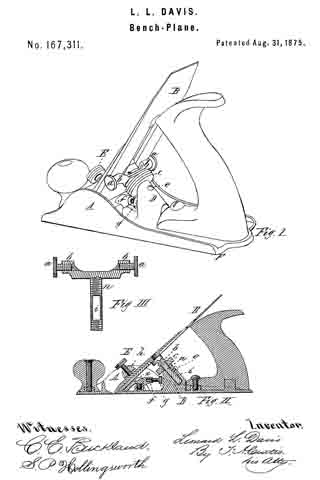
Be it known that I, LEONARD L. DAVIS, of Springfield, in the State of Massachusetts, have invented a new and useful Improvement in Bench-Planes; and I do hereby declare that the following is a full, clear, and exact description thereof, reference being had to the accompanying drawings making a part of this specification, and to the letters of reference marked thereon, in which —
Figure 1 is a perspective view of my invention. Fig. 2 is a longitudinal vertical section of the same; and Fig. 3 is a longitudinal section through the plane-iron support, showing the mechanism to adjust the plane-iron laterally.
My invention relates to the adjusting mechanism of a bench-plane; and it consists of an abutting piece made upon the plane, into which is inserted the threaded pin of a support, upon which the plane-iron rests, said support being provided with a threaded hole at each end, into which is turned a screw-guide. The threaded pin of the support is adjusted in or out of the abutment by means of a threaded nut, through which the pin is turned, the nut having a bearing against the abutment. The wedge, upon which the lower end ofthe plane-iron rests, is provided with a threaded hole, into which is turned a thumb-screw, abutting at its rear end against the before-mentioned abutment, so that the wedge may be thrust forward beneath the plane-iron more or less by turning said thumb-screw, and the wedge may be set or secured by a set-screw. A cross-bar, extending across from one side of the plane to the other, is provided with a threaded hole, into which is turned a thumb-screw, bearing against the front of the plane-iron.
In the drawings, A represents the sides of the plane, and F the base, upon which is made the abutment D, provided with a hole made obliquely therein, into which slides freely the thread-pin n. This pin is provided at the top with the cross-piece or support b, in each end of which is made a threaded hole, with a screw, a, turned therein, this screw a being provided with a large flanged head, as shown clearly in Fig. 1. A thumb-nut, c, is first turned upon the threaded pin n, and the latter is then inserted in the oblique hole made in the abutment; and to prevent the pin n from being accidentally lost out at any time a part of the pin is flattened at i, and a small screw, e, is turned into the abutment, and into the flattened part i, but not against the pin. As the pin at is thus arranged in the abutment, as shown in Fig. 2, the plane-iron B may rest upon the support b, between the screw-heads a a, one on each side. A thumb-screw, g, is turned into the rear part of the wedge f the rear end of the thumb-screw abutting against the abutment D, and slots are made through the wedge, through which set-screws as are turned into the base of the plane. A cross-bar, h, extends across from one side, A, of the plane to the other in front of the plane-iron, said bar having a threaded hole, into which is turned a thumb-screw, E, bearing against the plane-iron in front.
When it is desired to remove the plane-iron for sharpening the thumb-screw E is loosened, and the iron B may be taken out. The throat of the plane may be made larger or smaller by turning the thumb-nut c, moving the pin n either in or out of the abutment, as the case may be, and raising or depressing the support b, and the plane-iron resting thereon.
If one side of the plane-iron should protrude through the throat more than the other the screw a on that side is turned into the support b, and the opposite one turned out correspondingly, until the desired lateral adjustment is obtained. If, after the plane-iron has been adjusted to the desired angle with the base of the plane, it should be desired to change the size of the throat in front of the edge of the iron, the thumb-screw g is turned either in or out, forcing the wedge f forward or backward, as the case may be, and when adjusted to the right point it is secured by turning in the set-screw x firmly. After the desired adjustments have been made of the support b and the wedge f the thumb-screw E is turned in firmly against the front of the plane-iron, and it is ready for use.
It is evident that a small cam or similar mechanism may be used to force back the plane-iron upon the wedge and the support b, as that is the only object of the screw E; but I prefer the latter as more convenient.
I am aware that various kinds of adjusting mechanisms have heretofore been made and used, and I do not claim the same, nor any part thereof; irrespective of the arrangement herein shown and described; but,
Having described my invention, What l claim as new is —
1. The combination of the adjustable support b, the lateral adjusting-screws a a, and the screw E, substantially as set forth.
2. The combination of abutment D, the adjustable support b, the threaded pin n, nut c, the lateral adjusting-screws a a, the wedge f and its screw g, and the clamping-screw E, substantially as herein described.
LEONARD L. DAVIS.
Witnesses:
T. A. CURTIS,
C. E. BUCKLAND.