
No. 390,574 – Plane (Marten Doscher) (1888)
UNITED STATES PATENT OFFICE.
_________________
MARTEN DOSCHER, OF NEW YORK, N. Y.
PLANE.
_________________
SPECIFICATION forming part of Letters Patent No. 390,574, dated October 2, 1888.
Application filed February 3, 1888. Serial No. 262,855. (No model.)
_________________
To all whom it may concern:
Be it known that I, MARTEN DOSCHER, a citizen of the United States, residing at New York city, State of New York, have invented certain new and useful Improvements in Planes; and I do declare the following to be a full, clear, and exact description of the invention, such as will enable others skilled in the art to which it appertains to make and use the same, reference being had to the accompanying drawings, and to the letters and figures marked thereon, which form part of this specification.
My invention relates to planes; and the novelty consists in the means employed to accurately adjust the double plane-iron without removing it from the stock. All of the planes having such an adjustment of the double plane-iron which have come to my knowledge possess some disadvantage, in that they either require special irons to be made, some work to be done upon the binding-screw, or prevent the usual simple relative adjustment of the plane-bit and cap-iron. In my invention I have sought to remedy these defects by providing a simple device attachable to the head of the binding-screw of the double plane-irons, whereby it can be adjusted in place by means of a screw attached thereto actuated by a milled-headed nut turning in fixed bearings on the plane-stock. By the use of this device an ordinary double plane-iron can always be used with the one stock, and the user and purchaser is not restricted to the special irons made by one manufacturer. It is simple, cheap, and efficient.
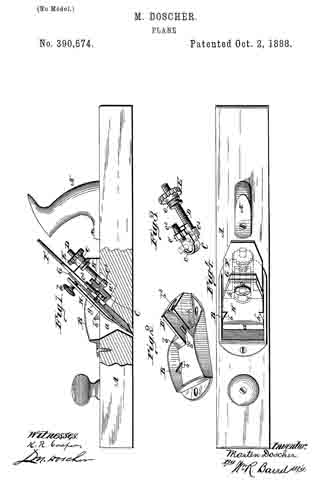
In the drawings, in which the same letters refer to the same parts in all the figures, Figure 1 is a vertical medial section and partial elevation of a plane containing my improved device. Fig. 2 is a perspective view of the top plate supporting and guiding the double plane-iron. Fig. 3 is a perspective view of the attachable clutch, and Fig. 4 is a top plan view of the stock containing the device.
A is the plane-stock, having the handle A’ and provided with the slotted opening a a’. On top of the stock and surrounding the opening is a casting, B B’, which I call the “top plate,” and which is securely fastened to the stock by screws or other suitable means. In front the top plate consists of the front wall and two side walls, B, each of which is provided with a wedge-shaped lug, b’, against which the wedge-iron H plays. In the rear the top plate consists of two side walls, B’, each of which terminates in a flange, lb, the upper surface of the walls and flanges serving as a guide and support for the double plane-iron. The rear side walls have each cast on their inside surfaces the lugs b3, serving to guide and support the attachable clutch C, and they have cast between them the rear wall, b2, hollowed out to form a bearing for the groove e of the milled-headed nut E. The cap-iron G and bit-iron F are of any usual form and are slotted and held together in the usual manner by the binding-screw g.
The attachable clutch C is provided with means to receive and firmly hold the head of the screw g. These consist of the semicircular flange c, which provides a broad bearing surface for the periphery of the screw-head, and the set-screw c2, with a slotted head moving in the fixed nut c’. On the under side of the clutch C, and preferably made integral with it, is the adjusting-screw D, operated by the milled-headed nut E, which turns in the bearing b2, formed in the rear wall of the top plate.
The method of using my device is obvious. The plane-bit F and the cap-iron G are iirst fastened together by the binding-screw g. The clutch C is then attached to the head of the screw g, the semicrcular flange c half surrounding the head and it being firmly secured in place by means of the set-screw c2, which has a slotted head at its outer end. The nut E is then placed upon the adjusting-screw D and the whole device is dropped into place in the slotted opening a a’ so that the bottom of the clutch C rests upon the lugs b3. The plane-bit F rests upon the flanges b, and the top surface of the side walls, B’, and the groove e fits into the bearing b2. The nut E is then turned until the double plane-iron is set at the desired position, when the wedge-iron H is put into place and tightened by means of the screw h, and the plane is ready for use.
I may vary the specific means employed to hold securely the head of the binding-screw in the attachable clutch without departing from the principle of my invention; but the means I employ seem to me to be the best and cheapest.
What I claim as new is —
1. In a plane, the combination, with the double plane-iron, of a binding screw the head of which is beneath the said double plane~iron, and an attachable clutch, as C, provided with suitable means for firmly holding the head of said binding-screw and adjusted by means of a set-screw, as D, operated by a nut, E, turning in fixed bearings on the plane stock.
2. I na plane, the attachable clutch C adapted to engage with and firnily hold the head of the binding-screw of the double plane-iron, the said clutch being provided with a top-flanged bearing-surface, as c, a set-screw, as c2, and an adjusting-screw, as D, actuated by a milled-headed nut, E, turning in fixed bearings.
3. In a plane, the top plate, B B’, provided with lugs b’ inside of its front side walls, adapted to serve with the wedge-iron of the plane, with other lugs, b2, inside of its rear side walls, adapted to serve as a guide and support to an attachable clutch, C, engaging the binding-screw of the double plane-iron, and the top surfaces of which walls serve as a guide and support to the said plane-iron, and the top rear wall of which constitutes a fixed bearing, b2, for the nut E, operating the adjusting-screw D of the said attachable clutch.
4. In a plane, the combination, with the double plane-iron and its binding screw, of an attachable clutch, as C, engaging the head of said binding-screw, and the top plate, B B’, having lugs, as b’ and b3, and the rear wall of which constitutes a fixed bearing for the operating-nut E of the adjusting-screw D of said attachable clutch, with said nut E, and adjusting-screw D, as set forth.
5. In combination with the binding-screw of a double plane-iron, whereof the plane-bit is slotted longitudinally and the cap-iron is provided with a threaded opening for the reception of said binding-screw, an attachable clutch, as C, placed beneath the double plane-iron, provided with suitable means for firmly holding the head of said binding-screw and other means for adjustment of the said clutch operated by the nut E, turning in fixed bearings.
In testimony whereof I affix my signature in presence of two witnesses.
MARTEN DOSCHER.
Witnesses:
JOHN H. COCHRAN,
L. M. DOSCHER.