
No. 167,772 – Improvement In Carpenters’ Planes (Matthias C. Mayo) (1875)
UNITED STATES PATENT OFFICE.
_________________
MATTHIAS C. MAYO, OF BOSTON , MASSACHUSETTS, ASSIGNOR TO J.
GARDNER WELD, OF SAME PLACE.
IMPROVEMENT IN CARPENTERS’ PLANES.
_________________
Specification forming part of Letters Patent No. 167,772, dated September 14, 1875; application filed July 14, 1875.
_________________
To all whom it may concern:
Be it known that I, MATTHIAS C. MAYO, of Boston, in the county of Suffolk and State of Massachusetts, have invented certain Improvements in Carpenters’ Planes, of which the following is a full, clear, and exact description, reference being had to the accompanying drawings, making part of this specification, in which —
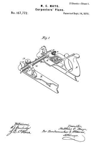
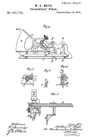
Figure 1 is a perspective view of a plane constructed in accordance with my invention. Fig. 2 is a side elevation of the same. Fig. 3 is a longitudinal vertical section on the line x x of Fig. 1. Fig. 4 is a transverse section on the line y y of Fig. 2. Fig. 5 is a transverse vertical section on the line z z of Fig. 2 ; Fig. 6, sectional detail.
My invention relates to that class of metallic planes for which Letters Patent of the United States were granted to Russell Phillips, August 13, 1867.
In these planes the adjustable gage which regulates the distance of the cutter from the edge of the work is supported upon a horizontal arm and secured, when adjusted, by a thumb-screw, the lower end of which enters a longitudinal groove or channel on the upper side of the arm.
This construction is, however, objectionable, as the point of the screw soon becomes worn, so that the gage cannot be securely confined upon the arm, and the tool becomes shaky; furthermore, the sides of the groove in the arm are liable to be indented by the screw, a ragged edge being thus produced, which interferes with the free movement of the gage.
The first part of my invention has for its object to remedy these difliculties; and consists in providing the sliding gage with a clamping device, which embraces the horizontal arm, and slides thereon with a spline or feather, by which construction any shifting of the gage, while the tool is being used, is effectually prevented.
My invention also consists in the peculiar construction of the gage by which the depth of the cut is regulated, this gage extending the entire or the greater portion of the length of the tool, and being provided with a clamping-screw near each end, the plate to which it is secured having a graduated scale at or near each end, by which means the tool is held perfectly level, and prevented from being tipped up at one end, as is liable to occur when the gage is placed just in front of the cutter, as heretofore, and the formation of a groove or out of equal depth throughout its entire length is thus insured.
My invention also consists in constructing the bottom plate of the plane with a lip or flange instead of with a square edge, as heretofore, the curvature of this lip corresponding to that of a portion of the edge of a bead-cutter of any size, the lip or flange serving as a guide for the cutter as soon as it begins to act, causing it to cut more gradually and smoothly than heretofore, and with less expenditure of power, thus forming a more perfect bead, while the narrow edge of the lip or flange admits of the formation of a wide bead with a narrow “quirk” or fillet, which it has not heretofore been possible to do with any tool made to cut beads of different widths.
My invention also consists in the peculiar construction of the lower end of the pivoted clamping-lever, which holds the cutter in place, whereby the clogging of the throat is effectually prevented.
To enable others skilled in the art to understand and use my invention, I will proceed to describe the manner in which I have carried it out.
In the said drawings, A represents the stock of the plane, which is formed of metal; B, the handle; and C, the bottom or sword plate. From one side of the stock A projects a horizontal arm or beam, D, which is held firmly in place by means of a screw-nut, a. Upon this arm D slides the metallic gage E, by adjusting the position of which the distance of the cutter b from the edge of the work may be regulated, as desired.
The gage is provided with a bracket, E’, supporting at its upper end a clamp, c, formed with a bearing, c’, and spline e, adapted to receive and embrace the longitudinal arm D. The upper portion of the clamp c, at c”, is cut through and provided with an extension, c”’, through which a tightening-screw, d, passes and engages with a corresponding extension, c””, formed on the bracket E’ and lower portion of the clamp-beaning c.
The gage is prevented from turning on the arm by the feather e on the arm D, which fits into a groove, f formed in the under side of the clamp; and by this device the gage is held rigidly upon the arm, and all liability of its position being changed while the tool is in use is effectually prevented; furthermore, when the screw d is loosened the gage E is always free to slide upon the arm D, which is not the case where the clamping-screw enters a groove in the arm, as heretofore.
The depth of the cut is regulated by an elongated gage, G, which is placed on one side of the plate C, and extends nearly its entire length.
From this gage project two vertical plates, g h, the plate g having a slot, i, through which passes a clamping-screw, k, and the plate h being provided with a clamping-screw, l, which passes through a slot, m, in the stock, and enters a slide, n, on the opposite side thereof, this slide having at its bottom a horizontal plate, P, which also serves as a gage, and, in connection with the gage G, effectually prevents the plane from being rocked laterally while in use, which would cause the opposite sides of the groove being cut to be of unequal depth; and, by means of the screws k l, the gages G P can be readily secured at any desired distance from the bottom of the plate G, so as to determine the degree of penetration of the cutter into the wood, the adjustment of the gage G being greatly facilitated by a graduated scale, q, near each end of the plate C.
By the employment of an elongated gage, G, extending the entire, or nearly the entire, length of the plate C, instead of a short gage placed just in front of the cutter, as heretofore, the operator is enabled to hold the tool perfectly level, and all liability of its being tipped up at one end, as was liable to occur with the old construction, is entirely avoided, and the formation of a groove or cut of equal depth throughout its entire length is thus insured.
The gage E is provided with a recess, r, for the reception of the gage P, which would otherwise prevent the gage E from being brought up as close to the plate C as might be desired.
The bottom of the plate C, instead of being made with a square edge, as heretofore, is formed with a projecting lip or flange, s, the curvature of which corresponds to that of a portion of the edge of a bead-cutter when secured in place, as seen in Fig. 6.
When a cutter of this description is employed, it is secured so as to project out on the inner side only of the plate G, as seen in Fig. 6, the cutting-points of the iron extending slightly below the bottom of the lip s, which thus serves as a guide for the cutter as soon as it commences to act, and also prevents the cutter from being forced deeply into the wood, as heretofore, which produces a rough and ragged edge, and the bead is thus caused to be cut gradually and smoothly and more perfectly than heretofore, and with less expenditure of power.
Any sized bead-cutter may be employed, and it will be seen that the narrow edge of the lip s will admit of the formation of a wide bead with a narrow quirk or fillet, which has heretofore been impracticable with any tool made to cut beads of various widths.
The cutter or iron b, which may be of any size or description desired, its into an inclined way, t, made to receive it, and is securely held by a clamping-lever, H, pivoted at 10 to the stock A.
Passing through the upper end of this lever is a thumb-screw, u, the lower end of which bears against the enlarged outer end of a spring-plate, v, secured to the under side of the lever, this plate, as the screw is turned, being brought down onto the upper end of the cutter, the further turning of the screw causing the lever H to be rocked in such manner as to bring its straight edge w firmly down upon the cutter at or near its center, the cutter being still further steadied in place by a groove in its under side, which fits over the edge 12 at the bottom of the way t.
The lever H thus admits of a cutter of any width or thickness being readily secured in place, while the enlarged end of the spring-plate v affords an extended bearing, so that the pressure of the screw may be exerted upon the entire width of the cutter.
The lower end of the lever H is provided with a concave or spoon-shaped enlargement, a’, arranged in such manner that it will receive the shavings as they issue through the throat b’ from the cutter b, and conduct the same sidewise clear of the upper surface of the throat, thereby effectually preventing any clogging of the throat by reason of the shavings accumulating above the same, as is the case with planes constructed in the usual manner.
On the side of each cutter is a pin, c’, by which it may be readily inserted, removed, or adjusted.
When the gage E and arm D are removed, which can be easily done, the plane can be ured as a dado, groover, rabbet, bead, V, or round plane, by merely inserting a cutter of the desired shape.
What I claim as my invention, and desire to secure by Letters Patent, is —
1. The divided clamp c, provided with bearing c’, slot f, and clamping-screw d, adapted to hold and embrace the arm D of a stock, A, substantially as shown and described.
2. The combination, with the sword-plate C, provided with a lip or flange, s, of the cutter b, pivoted clamping-lever H, provided with concave enlargement a’ and adjustable gage E, substantially as shown and described.
Witness my hand this 6th day of July, A.D. 1875.
MATTHIAS O. MAYO
In presence of —
N. W. STEARNS,
P. E. TESCHEMACHER.