
No. 636,830 – Bench-Plane (Henry Miller) (1899)
UNITED STATES PATENT OFFICE.
_________________
HENRY MILLER, OF MEXICO, PENNSYLVANIA.
BENCH-PLANE.
_________________
SPECIFICATION forming part of Letters Patent No. 636,830, dated November 14, 1899.
Application filed October 29, 1898. Serial No. 694,958. (No model.)
_________________
To all whom it may concern:
Be it known that I, HENRY MILLER, a citizen of the United States, residing at Mexico, in the county of Juniata and State of Pennsylvania, have invented a new and useful Bench-Plane, of which the following is a specification.
This invention relates to bench-planes; and it has for its object to equip a plane of this character with improved bit-adjusting mechanism which shall provide simple and efficient means for positively and quickly adjusting the bit or knife of the plane to a proper working position.
To this end the main and primary object of the invention is to provide an improved bit-adjusting device for planes having means for effecting a compound adjustment of the bit — to wit, a longitudinal adjustment to secure the proper “set” of the cutting edge in the bit-opening and a lateral adjustment to accurately center the bit.
A further object of the invention is to provide improved means in connection with the bit-adjusting device for securely holding the clamping-plate of the bit, so as to prevent longitudinal displacement thereof after the parts have been set and tightened up.
With these and other objects in view, which will readily appear as the nature of the invention is better understood, the same consists in the novel construction, combination, and arrangement of parts hereinafter more fully described, illustrated, and claimed.
While the improvements contemplated by the present invention are necessarily susceptible to modidcation without departing from the principle or scope of the invention, still the preferred embodiment thereof is shown in the accompanying drawings, in which —
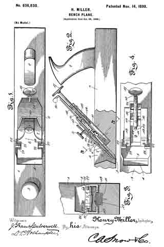
Figure 1 is a plan view of a bench-plane fitted with the improvements contemplated by the invention. Fig. 2 is a vertical longitudinal sectional view of the plane. Fig. 3 is a transverse sectional view on the line 3 3 of Fig. 2. Fig. 4 is a plan view of the plane-stock equipped with the improvements and showing the plane bit or knife and the clamping-plate therefor removed.
Referring to the accompanying drawings, the numeral 1 designates the plane-stock of an ordinary bench or smoothing plane, provided near its opposite ends with the usual handle and knob, (designated by the numerals 2 and 3, respectively,) and at an intermediate point the said plane-stock is provided with the mouth 4, communicating with the transverse bit-opening 5 at the under side of the stock and receiving therein the plane bit or knife 6. The plane bit or knife 6 is arranged in the usual inclined position within the mouth 4, with its cutting end disposed in the transverse bit-opening 5, and said plane bit or knife 6 has fitted to the upper side thereof the usual adjustable cap-plate or back iron 7, whose lower end is beveled and adjustable relatively to the cutting end of the bit or knife 6 in the usual manner, according to the character of the work required of the plane. Cooperating with the plane bit or knife 6 and the cap-plate 7 is the clamping-plate 8, which is arranged on top of the latter and carries at its upper end the clamping-screw 9, whose inner end works against a clamping-spring 10, secured fast at one end to the under side of the plate 8 and adapted to have its free end pressed by the screw 9 tightly against the cap-plate of the plane bit or knife to provide for clamping the same rigid after being set, this combination and arrangement of parts being common to most of the ordinary types of bench or smoothing planes.
To provide for adapting the adjusting device or mechanism to the parts of the plane just described, a guide-boxing 11 is securely fastened at its lower end by means of screws or other suitable fasteners within the plane-mouth 4, and said guide-boxing 11 is provided with a central longitudinal channel or way 12 and opposite side rest-flanges 13, which follow the inclination of the blade-seat next to the transverse bit-opening 5, so as to form an even rest or support for the plane bit or knife. The said guide-boxing 11, by reason of its inclination and the provision of the flanges 13, forms an extended inclined support or rest for the plane bit or knife 6, and the longitudinal channel or guideway of said boxing accommodates for movement therein a slide-block 14, to which is swiveled one end of an adjusting-screw 15, working through a fixed nut 16, secured fast to the boxing, near the upper end thereof, and the upper outer end of said adjusting-screw 15 carries an adjusting disk or wheel 17, which by being turned provides for the sliding movement of the block 14 in the direction desired.
The slide-block 14 has pivotally mounted thereon a laterally-swinging adjusting-lever 18, which lever is provided below its pivotal connection with the block with an upstanding stud 19, having a loose or pivotal engagement in the stud-opening 20, formed in the plane bit or knife G or the cap-plate thereof. At its upper outer end, which projects beyond the upper end of the boxing 11, the said lever 18 is provided with a laterally-deflected thumb-piece 21, which is grasped to provide for swinging or adjusting the lever on its pivot.
From the foregoing it will be readily understood that in order to secure the longitudinal adjustment of the plane bit or knife to provide for the proper set of its cutting edge in the bit-opening it is simply necessary to turn the disk or wheel 17, which will cause a longitudinal movement of the slide-block, as well as the adjusting-lever 18, carried thereby, and which connects with the plane bit or knife. To correct any angularity of the bit or knife and thereby properly center the same, a lateral movement of the adjusting-lever on its pivot will effect this result, and at this point it will be observed that the adjusting-lever and the plane bit or knife are arranged in substantial parallelism, thereby permitting the adjusting-screw a free play through the entire length of its threaded portion, while at the same time providing for exerting a direct longitudinal pressure on the bit in adjusting the same backward or forward, which would not be the case if the adjusting-screw were arranged at an angle to the plane of the bit.
In addition to the adjusting device described the present invention also contemplates the use of a pair of holding-arms 22. These holding-arms 22 are fitted to the guide-boxing, within the plane-mouth, at opposite sides thereof and at right angles to the inclination of the plane bit or knife, and at their upper ends the said holding-arms are provided with inwardly-projecting gripping-lugs 23, which overhang the side edges of the clamping-plate 8, and are provided with pointed edges 24, engaging superlicial serrations 25 at opposite edges of the clamping-plate 8. This construction prevents longitudinal displacement of the clamping-plate 8 after the parts have been properly set and tightened up by means of the screw 9.
From the foregoing it is thought that the construction, operation, and many advantages of the herein-described plane attachment will be readily apparent to those skilled in the art without further description, and it will be understood that changes in the form, proportion, and the minor details of construction may be resorted to without departing from the principle or sacrificing any of the advantages of this invention.
Having thus described the invention, what is claimed as new, and desired to be secured by Letters Patent, is —
1. In a plane, the combination with the stock and the bit or knife, of a channeled guide-boxing fitted to the stock, a longitudinally-adjustable slide-block completely housed and concealed within the channel of the boxing, and a laterally-swinging adjusting-lever pivoted between its ends to the block and provided at its lower end with an upturned stud loosely engaging with the bit or knife, substantially as set forth.
2. In a plane, the combination with the stock, and the bit or knife, of a channeled guide-boxing fitted to the stock, a fixed nut housed within the boxing at or near its upper end, a slide-block registering and concealed within the channel of the boxing, an adjusting-screw mounted in said nut and having a connection with the slide-block, and a laterally-swinging adjusting-lever pivoted between its ends to the block and provided with an upturned stud loosely engaging with the bit or knife, substantially as set forth.
3. In a plane, the combination with the stock, the bit or knife, and the clamping-plate, of a guide-boxing fitted to the stock, adjusting devices for the bit or knife arranged within the guide-boxing, and a pair of holding-arms fitted to the guide-boxing at opposite sides thereof, within the plane-mouth, and provided at their upper ends with inwardly-projecting gripping-lugs overhanging and engaging the side edges of the clamping-plate, substantially as set forth.
In testimony that I claim the foregoing as my own I have hereto affixed my signature in the presence of two witnesses.
HENRY MILLER.
Witnesses:
SAMUEL LAPP,
W. N. ZEIDERS.