No. 917,915 – Bench-Plane (Willem H. J. Vander Toorn) (1909)

UNITED STATES PATENT OFFICE.
_________________
WILLEM H. J. VANDER TOORN, OF FLUSHING, NETHERLANDS.
BENCH-PLANE.
_________________
917,915. Specification of Letters Patent. Patented April 13, 1909.
Application filed July 2, 1908. Serial No. 441,707.
_________________
To all whom it may concern:
Be it known that I, WILLEM H. J . VANDER TOORN, a subject of the Queen of the Netherlands, residing at Flushing, Netherlands, have invented certain new and useful lmprovements in Bench-Planes; and I do hereby declare the following to be a full, clear, and exact description of the same, reference being had to the accompanying drawings, forming a part of this specification, and to the figures and letters of reference marked thereon.
The present invention relates to bench planes, the objects of the invention being to provide a plane of strong and simple construction conveniently having a stock of wood and embodying an improved form of adjustable fore sole and side guide, all as will be hereinafter described in detail and pointed out particularly in the appended claims.
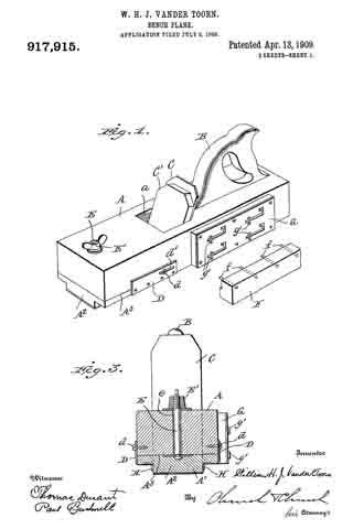
In the accompanying drawings: Figure 1 is a perspective view of a plane embodying the present improvement, the side guide being shown detached. Fig. 2 is a longitudinal section on a central plane. Fig. 3 is a transverse section through the front end of the stock. Fig. 4 is a cross section in rear of the plane iron or bit with the side guide in place.
Similar letters of reference in the several figures indicate the same parts.
The stock A of the plane is preferably of hardwood and has the usual handle or tool B and slot a, for the plane iron or bit C. This bit while shown as a single bit may be of the usual double type, and is held in place by the wedge C’ or other ordinary or preferred securing means. In accordance with the present invention the cutting edge of the bit is equal in length to the width of the sole and as a most convenient construction to accomplish this end the sole A’ is narrower than the body of the stock, as shown clearly in Figs. 3 and 4.
The portion A2 of the sole forward of the bit is made separate from the stock and is adjustably mounted thereon in a diagonal plane in order to raise or lower the same and to simultaneously adjust the width of the mouth. Conveniently, the forward end of the stock is made with its under face at a slight inclination to the plane of the sole and the upper face of the adjustable fore sole is correspondingly inclined, the two surfaces forming guide ways along the line A3, which is only slightly inclined to the sole, whereby an exceedingly accurate adjustment of the level of the fore sole is possible. For retaining the adjustable fore sole in its adjusted position it is provided with side plates D embracing the stock and set screws d working in slots d’, also with a bolt E extending upwardly through a slot e in the stock and provided at its upper end with a thumb nut E’.
In rear of the bit a downwardly projecting side guide F is removably clamped to the side of the sole under the overhang of the stock, the preferred means for holding the side guide in place embodying a series of pins f in the side guide adapted to enter sockets f’ in the sides of the sole. A plate G held to the side of the stock by square headed screws g passing through L-shaped slots g’ is adapted when dropped down to the position shown in Fig. 4. to clamp the side guide in position. When the plate G is in its lowered position the screws rest in the extremities of the L-shaped slots, whereby any movement of the plate backwardly or upwardly will be prevented, and no accidental displacement of the side guide can occur while the plane is being used.
To guide shavings into the mouth, thin angle iron side plates H may be located on each side of the knife, care being taken that the lower edges of the plates never project below the bottom of the fore sole.
Certain advantages result from the construction of the sole and cutting edge of the bit of the same width and from making the fore end of the sole adjustable in level with respect to the rear end. Thus were the sole of greater width than the bit some part would be in position to rest on the high levels of the work and consequently the plane would be unstable or would make a cut of uneven depth but with the cutting edge of the bit of a length equal to the width of the sole, as herein set forth, the fore end will rest squarely on the work in front of the cut, the rear end will rest squarely on the work in the cut, and the depth of the cut is accurately determined by the difference in level of the two parts of the sole.
As the cutting edge does not project below the rear part of the sole it is not in contact with the work during reverse movement of the plane, nor is it liable to be injured by the bench or other surface on which the plane rests when not in use.
Having thus described the invention, what is claimed, is:
1. A bench plane embodying a stock having a sole narrower than the body of the stock, the forward end of the sole being adjustable to different levels parallel with the plane of the rear portion and a bit having a cutting edge equal in length to the width of the sole.
2. A bench plane embodying a stock having a downwardly projecting sole and laterally projecting body, the portion of the sole forward of the mouth being adjustable longitudinally and vertically, means for clamping the fore end of the sole in adjusted position, and a bit having a cutting edge equal in length to the width of the sole.
3. A bench plane embodying a stock having a downwardly projecting sole and laterally projecting body, a bit of equal width to the sole, an edge guide removably secured to the side of the sole under the overhang of the body, and a vertically movable edge guide securing plate mounted on the side of the body.
4. A bench plane embodying a stock having a downwardly projecting sole and laterally projecting body, the end of the sole forward of the mouth being longitudinally and vertically adjustable, and an edge guide secured beneath the body and against the side of the sole in rear of the mouth.
WILLEM H. J. VANDER TOORN
Witnesses:
P. ROLDAUM
C. Y. FÉLIN


