No. 586,712 – Plane (Charles A. Paul) (1897)

UNITED STATES PATENT OFFICE.
_________________
CHARLES A. PAUL, OF ORLANDO, OKLAHOMA TERRITORY.
PLANE.
_________________
SPECIFICATION forming part of Letters Patent No. 586,712, dated July 20, 1897.
Application filed May 11, 1897. Serial No. 591,136. (No model.)
_________________
To all whom it may concern:
Be it known that I, CHARLES A. PAUL, a citizen of the United States, residing at Orlando, in the county of Logan and Territory of Oklahoma, have invented certain new and useful Improvements in Planes; and l do hereby declare the following to be a full, clear, and exact description of the invention, such as will enable others skilled in the art to which it appertains to make and use the same.
This invention relates to planes, and more particularly to plane-bits.
My object is to provide an improved and simple plane-bit which will be capable of quick and easy adjustment or removal.
The invention consists of certain novel features and combinations appearing more in detail hereinafter.
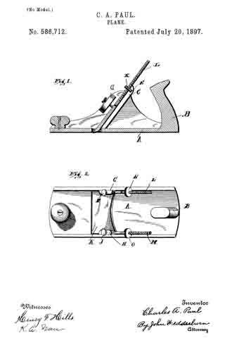
In the accompanying drawings, Figure 1 is a sectional side elevation, and Fig. 2 a top view.
A designates the plane-body, which is provided with the usual handle B.
The sides of the body are provided with respective rearwardly-inclined bit-slides C, which have arc-shaped notches E in their upper ends. I also proyide the sides with inwardly-projecting lugs G and H, through which pass respective clamping-screws I and J.
My improved bit K is provided with integral upwardly-projecting screws L and M, on which are located circular adjusting-nuts N and O, which project into the notches E and F.
The bit is adjusted in the following manner: The nuts are turned to advance or retreat the bit, and when properly adjusted the clamping screws are screwed down, thus holding the bit firmly in adjusted position. The bit is not quite the width of the plane-body, so that either nut can be adjusted to slightly tilt it either to the right or left, so that the cutting edge will lie parallel with the bottom of the plane.
Having thus described the invention, what is claimed as new is —
1. In a plane, the combination with a plane-body of inclined bit-slides securely fastened thereto, a bit having screw-threaded arms, located at opposite sides thereof and secured thereto and nuts carried on said arms and engaging with the bit-slides whereby either or both sides of the bit can be adjusted.
2. In a plane, the combination with a plane-body, of inclined bit-slides secured thereto, said slides being provided with notches, a bit movable on the slides and having screw-threaded arms secured thereto and located at opposite sides thereof, and circular nuts carried on the arms and loosely received in the notches.
3. In a plane, the combination with a plane-body, of inclined bit-slides securely fastened thereto, said slides being provided with notches, a bit movable on the slides and having screw-threaded arms at its opposite sides, nuts carried on the arms and loosely received in the notches, ears secured to the plane-body, and clamping-screws passing through the ears and binding on the bit-slides.
4. In a plane, the combination with a plane-body, of bit-slides secured to the body, a bit movable on said slides, said bit being provided with integral screw-threaded arms L and M, circular nuts N and O loosely received on the bit-slides, and clamping-screws I and J adapted to bind on the bit-slides.
5. The combination with the plane-stock having its sides provided with rearwardly-inclined bit-slides and arc-shaped notches at their upper ends and lugs projecting inwardly from the inner walls of the opposite sides, of a bit mounted for movement in said slides beneath said lug and provided with integral upwardly-projecting screws, one at each edge, nuts on said screws projecting into said notches and set-screws passed through said inwardly-extending lugs at right angles to the screws and bearing against the bit whereby the bit may be adjusted in either direction by manipulation of said nuts and also tilted to either the right or left to bring the cutting edge thereof parallel with the bottom of the plane, substantially as described.
In testimony whereof I have signed this specification in the presence of two subscribing witnesses.
CHARLES A. PAUL.
Witnesses:
J. D. TOWNSEND,
E. J. HEDRICK.


