
No. 640,546 – Hand-Plane (Philo F. Dresser) (1900)
UNITED STATES PATENT OFFICE.
_________________
PHILO F. DRESSER, OF GLENWOOD, IOWA.
HAND-PLANE.
_________________
SPECIFICATION forming part of Letters Patent No. 640,546, dated January 2, 1900.
Application filed November 1, 1898. Serial No. 735,127. (No model.)
_________________
To all whom it may concern:
Be it known that I, PHILO F. DRESSER, a citizen of the United States, residing at Glenwood , in the county of Mills and State of Iowa, have invented certain new and useful Improvements in Hand-Planes; and I do declare the following to be a full, clear, and exact description of the invention, such as will enable others skilled in the art to which it appertains to make and use the same.
This invention relates to improvements in hand-planes and more particularly to that class in which the bit or plane-iron is both longitudinally and laterally adjustable; and the object is to provide a simple, inexpensive, and effective means for accomplishing this purpose; and a further object is to rigidly secure the bit in the position to which it has been adjusted, so as to prevent accidental displacement while in use.
To these ends the invention consists in the construction, combination, and arrangernent of the device, as will be hereinafter more fully described, and particularly pointed out in the claim.
In the accompanying drawings the same reference characters indicate the same parts of the invention.
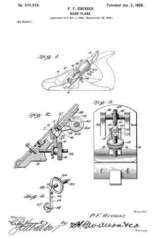
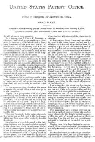
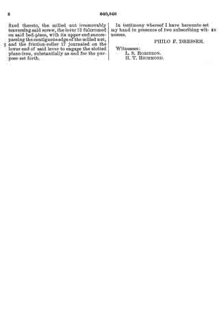
Figure 1 is a perspective view of a plane embodying my invention, the stock and bit being shown in dotted lines, while the bed-piece and the mechanism for adjusting the bit are shown in full lines. Fig. 2 is a longitudinal section through the bit and bed-piece. Fig. 3 is a bottom plan view of the bed-piece. Fig. 4 is a perspective detail view of the lever-operating mechanisrn for laterally adjusting the bit.
1 denotes the stock; 2, the wedge-clamp ; 3, the plane-iron or bit, and 4 the bed-piece, which may form a part of or be rigidly fixed to the stock.
5 designates a lever fulcrumed in the bed-piece, its inner arm 6 extending into a recess 7 in the plane-iron, while its outer arm 8 is bifurcated to encompass the cylindrical shank 9 of the milled-head nut 10, adjustably mounted on the threaded stud 12, rigidly fixed in the bed-piece. It will be seen that by adjusting the milled-head nut 10 on the fixed stud 12 a longitudinal adjustment of the plane-iron is effected.
13 designates a lever fulcrumed on a stud 14, fixed in the lower face of the bed, and its shorter arm is formed with a lateral boss 15, carrying a pin 16, on the projecting end of which is journaled an antifriction-roller 17, which extends into the usual longitudinal slot 18 in the plane-iron. The opposite or longer end of the lever 13 is formed with two parallel lugs 19 19, extending in an opposite direction to the boss 15 to encompass the sides of the periphery of the milled nut 20, mounted on the transverse screw 21, rigidly fixed in the parallel brackets 22 22, formed integral with the bed-piece. It will thus be seen that a rotary movement of the nut 20 causes it to travel longitudinally on the fixed screw 21 and carry the free end of the lever 13 with it. This movement causes the inner end of the said lever to move in a correspondingly-opposite direction and carry the plane-iron with it, thereby providing for the lateral adjustment of the plane-iron.
I am aware that the plane-iron has heretofore been adjusted by rneans of a lever, but the free end of the lever projected beyond the upper end of the bed-piece for convenience of manipulation and in this exposed position was liable to accidental displacement, there being no means provided for locking the free end of the lever. In the present construction it will be observed that the nut 20 when not rotating acts as a lock for the outer end of the lever 13, and thereby prevents its movement in either direction.
The accompanying drawings show my invention in the best form now known to me, but many changes in the details might be made within the skill of a good mechanic without departing from the spirit of my invention as set forth in the claim at the end of this specification.
Having thus fully described my invention, what I claim as new and useful, and desire to secure by Letters Patent of the United States, is —
In a hand or bench plane having a laterally-adjustable plane-iron, the bed-piece 4 fined to the stock and the transverse screw 21 rigidly fixed thereto, the milled nut irremovably traversing said screw, the lever 13 fulcrumed on said bed-piece, with its upper end encompassing the contiguous edge of the milled nut, and the friction-roller 17 journaled on the lower end of said lever to engage the slotted plane-iron, substantially as and for the purpose set forth.
In testimony whereof I have hereunto set my hand in presence of two subscribing wltnesses.
PHILO F. DRESSER.
Witnesses:
L. S. ROBINSON.
H. T. RICHMOND.