
No. 12,234 – Bench Plane (William C. Hopper) (1855)
UNITED STATES PATENT OFFICE.
_________________
WILLIAM C. HOPPER, OF PITTSBURG, PENNSYLVANIA.
BENCH-PLANE.
_________________
Specification of Letters Patent No. 12,234, dated January 16, 1855.
_________________
To all whom it may concern:
Be it known that I, WILLIAM C. HOPPER, of Pittsburg, in the county of Allegheny and State of Pennsylvania, have invented a new and useful Improvement in Planes; and I do hereby declare that the following is a full and exact description thereof, reference being had to the annexed drawings, forming part of this specification, in which —
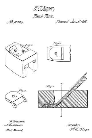
Figure 1, is a longitudinal sectional through the center of the plane; Fig. 2 is a perspective view of the mouth piece of my improved plane. Fig. 3, is a perspective view of a section of my plane through x. x, in Fig. 1, turned up so as to show the underside of the plane, and with the mouth piece removed. Fig. 4, is a representation of the underside or face of the plane to show the position of the mouth piece.
My invention is especially designed for planes to be used in fine work, where great smoothness of finish is required, but is also very applicable with great advantage to all kinds of planes, from the smoothing plane to the jack plane.
It consists in so arranging the parts of the plane that the chisel is placed in front of its wedge, and rests against the front shoulder in the cavity of the plane, in combination with the use of a mouth piece on the face of the plane in front of the edge of the chisel to serve as a rest for the chisel and to confine the throat of the plane.
In order to enable others skilled in the art to make and use my improved plane I will proceed to explain its construction and operation.
In the drawings a, is the mouth piece which may be constructed of iron, bone, brass, hardwood or other suitable material.
The shape of the mouth piece shown in Fig. 1, is that which I prefer, but any other shape may be adopted which will accomplish the same object, as I do not desire to confine my invention to the peculiar shape of mouth piece herein described. The mouth piece is attached to the plane by a screw s, which passes through the plate b, of the mouth piece. When set in the plane, the surface of the plate b, lies flush with the face of the plane, and rests on three wood screws s’, s’, s’, which are nicely adjusted so as to afford a firm bed for it, parallel to the face of the plane. The mouth piece is of the same width as the chisel or bit c. The two arms d, d, at either side of the mouth piece, project upward into the cavity of the plane, at the same angle to the face of the plane as that at which the chisel is to be set. These arms serve as rests for the end of the bit c.
The bit or chisel is inserted in the plane in front of the wedge e, and rests against the front shoulder, against which it is pressed by the wedge. The bit is thus held firmly in its place throughout its whole length, which prevents it having any spring, and causes it to work much more smoothly. A slight space is left between the points or edge of the bit c, and the edge of the face of the mouth piece, sufficient to allow of the passage of the chip or shaving between them into the cavity of the plane; but the mouth piece is so close to the edge of the bit as to prevent the plane ripping or splintering the wood, even in the slightest degree, which would be the case if the plane had an open throat; and this arrangement causes the plane to work so smoothly that it may be used even for planing veneers, which cannot be done at all with safety with any plane of the ordinary construction. My arrangement in combination with the use of a mouth piece also enables me to dispose with the use of a cap or double bit.
By constant use the face of a plane gradually wears away, in which case it will be necessary to sink the mouth piece lower down in the hole made for its reception. If the mouth piece were sunk down at right angles to the face of the plane, it is evident, that as the bit is set in the plane at an angle of about 45 degrees, the bit as the plane wears away would recede from the mouth piece; it would no longer rest against the arms of the mouth piece, and the throat of the plane, through which the shavings pass would become too wide. To remedy this inconvenience and enable the mouth piece to be accurately adjusted to the bit, I adopt the following arrangement: The extreme edge of the mouth piece is beveled to the same angle as that at which the bit of the plane is set, as will be seen in Fig. 1; the corresponding wall of the recess in which the mouth piece is sunk, (marked f, in Fig. 3,) is also inclined at the same angle.
When the plane requires to be refaced, the screw, s, is unscrewed, and the mouth piece is taken out. The adjusting screws, s’, s’, s’, are lowered as much as it is desired to sink the mouth piece, and the mouth piece is replaced. Now as the edge of the mouth piece which rests against the wall of its recess, as well as the wall f, itself is beveled, the mouth piece in sinking into its recess, is pushed forward toward the bit, just as far as the bit has receded, and their relative position is exactly maintained, so that the sides of the bit will rest as before against the projecting arms of the mouth piece. The screw s, is also set into the plane at an angle, so that it allows for this lateral adjustment of the mouth piece, and avoids the necessity of making a new hole for the screw s.
As I remarked before, the form of the mouth piece may be varied without altering the principle involved; the simplest form which can be used, is to screw a plate of metal, countersunk into the face of the plane, immediately in front of the edge of the bit; but this only partially accomplishes the object of my invention as it does not serve as a rest for the end of the bit, nor is it capable of so easy and accurate adjustment.
Having thus described my improvement in planes, what I claim as my invention and desire to secure by Letters Patent, is —
The constructing of planes with the chisel or bit set in front of its wedge, in combination with the use of a mouth piece, substantially in the manner and for the purposes hereinbefore described.
WM. C. HOPPER.
Witnesses:
N. B. KENASTON,
WM. N. HOWARD.