No. 637,463 – Router (Reuben Hegarty) (1899)

UNITED STATES PATENT OFFICE.
_________________
REUBEN HEGARTY, OF BIGLER, CLEARFIELD COUNTY, PENNSYLVANIA,
ASSIGNOR OF ONE-THIRD TO PEARL T. DAVIS, OF CLEARFIELD, PENNSYLVANIA.
ROUTER.
_________________
SPECIFICATION forming part of Letters Patent No. 637,463, dated November 21, 1899.
Application filed March 18, 1899. Serial No. 709,562. (No model.)
_________________
To all whom it may concern:
Be it known that I, REUBEN HEGARTY, a citizen of the United States, residing at Bigler township, in the county of Clearfield and State of Pennsylvania, have invented certain new and useful Improvements in Routers; and I do declare the following to be a full, clear, and exact description of the invention, such as will enable others skilled in the art to which it appertains to make and use the same.
The invention has relation to routers.
The object of the invention is to provide a simple, durable, and inexpensive tool of this character which will perform its work in an efficient and rapid manner, making a cut on each stroke, both forward and backward.
With this object in view the invention consists in certain features of construction and combination of parts, which will be hereinafter fully described and claimed.
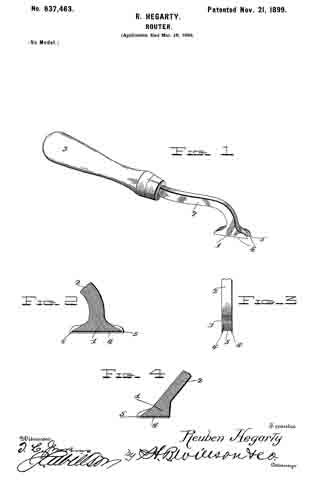
In the drawings, Figure 1 is a perspective view of my improved tool. Fig. 2 is a longitudinal sectional view through the cutting-head of the tool. Fig. 3 is an end view of the cutting-head of the tool. Fig. 4 is a modification.
In the drawings, 1 denotes the cutting-head of the tool, 2 its shank, and 3 its handle. The cutting-head of the tool is provided with two longitudinal vertical cutters 4 and with two chisel-shaped transverse end cutters 5 and 6, which are arranged above the cutting edges of the longitudinal cutters 4 and intermediate the extreme ends of said cutters 4.
In operation on the forward stroke of the tool the longitudinal cutters will make the vertical cut and the transverse cutter 5 will make the horizontal cut. On the return stroke of the tool the longitudinal cutters will make the vertical cut and the cutter 6 will make the horizontal cut. It will thus be seen that the tool cuts on its forward and backward stroke.
Various changes in the form, proportion, and the minor details of construction may be resorted to without departing from the spirit or sacrificing any of the advantages of this invention. For instance, if desired, the shank may be made straight, as shown in Fig. 4, and one (preferably the rear) transverse cutter rnay be dispensed with. Of course in this construction there would not be a cut at each movement of the tool.
Having thus described the invention, what is claimed, and desired to be secured by Letters Patent, is —
1. A tool consisting of a handle, a shank, and a cutter-head, the handle and shank projecting upwardly and rearwardly of the cutter-head, said cutter-head formed with longitudinal cutting edges and with transverse cutting edges arranged at either end of the head and above the longitudinal cutting edges, substantially as and for the purpose set forth.
2. A tool consisting of a handle, a shank, and a cutter-head, the handle and shank projecting upwardly and rearwardly of the cutter-head, said cutter-head formed with longitudinal cutting edges and with transverse cutting edges arranged at either end of the head above and between the sides of the longitudinal cutting edges, substantially as and for the purpose set forth.
3. A tool consisting of a handle, a shank, and a cutter-head, the handle and shank projecting upwardly and rearwardly of the cutter-head, said cutter-head formed with longitudinal cutting edges and with transverse cutting edges arranged at either end of the head and above and intermediate the ends of the longitudinal cutting edges, substantially as and for the purpose set forth.
4. A tool consisting of a handle, a shank and a cutter-head, the handle and shank projecting upwardly and rearwardly of the cutter-head, said cutter-head formed with longitudinal cutting edges and with transverse cutting edges arranged at either end of the head and above and intermediate the length and between the edges of the longitudinal cutting edges, substantially as and for the purpose set forth.
5. A tool consisting of a handle, a shank, and a cutter-head, the handle and shank projecting upwardly and rearwardly of the cutter-head, said cutter-head formed with longitudinal cutting edges and with a transverse cutting edge arranged at one of the ends of the head above the longitudinel cutting edges, substantially as and for the purpose set forth.
In testimony whereof I have hereunto set my hand in presence of two subscribing witnesses.
REUBEN HEGARTY.
Witnesses:
DENTON BEEMAN,
C. L. CORNELY.


