
No. 43,360 – Improvement In Bench Planes (Stephen Williams) (1864)
UNITED STATES PATENT OFFICE.
_________________
STEPHEN WILLIAMS, OF PHILADELPHIA, PENNSYLVANIA.
IMPROVEMENT IN BENCH-PLANES.
_________________
Specification forming part of Letters Patent No. 43,360, dated June 28, 1864.
_________________
To all whom it may concern:
Be it known that I, STEPHEN WILLIAMS, of Philadelphia, in the county of Philadelphia and State of Pennsylvania, have invented a new and useful Improvement in Smoothing-Planes; and I do hereby declare that the following is a full, clear, and exact description thereof, which will enable others skilled in the art to make and use the same, reference being had to the accompanying drawings, making a part of this specification, in which —
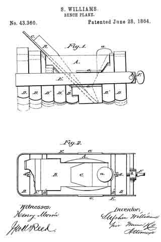
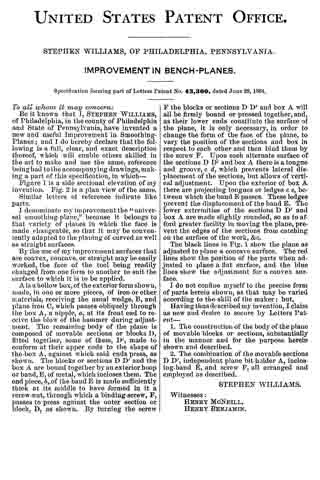
Figure 1 is a side sectional elevation of my invention. Fig. 2 is a. plan view of the same.
Similar letters of reference indicate like parts.
I denominate my improvement the “universal smoothing-plane,” because it belongs to that variety of planes in which the face is made changeable, so that it may be conveniently adapted to the planing of curved as well as straight surfaces.
By the use of my improvement surfaces that are convex, concave, or straight may be easily worked, the thee of the tool being readily changed from one form to another to suit the surface to which it is to be applied.
A is a hollow box, of the exterior form shown, made, in one or more pieces, of iron or other materials, receiving the usual wedge, B, and plane iron C, which passes obliquely through the box A, a nipple, a, at its front end to receive the blow of the hammer during adjustment. The remaining body of the plane is composed of movable sections or blocks D, filted together, some of them, D’, made to conform at their upper ends to the shape of the box A, against which said ends press, as shown. The blocks or sections D D’ and the box A are bound together by an exterior hoop or band, E, of metal, which incloses them. The end piece, b,.of the band E is made sufficiently thick at its middle to have formed in it a screw-nut, through which a binding-screw, F, passes to press against the outer section or block, D, as shown. By turning the screw F the blocks or sections D D’ and box A will all be firmly bound or pressed together, and, as their lower ends constitute the surface of the plane, it is only necessary, in order to change the form of the face of the plane, to vary the position of the sections and box in respect to each other and then bind them by the screw F. Upon each alternate surface of the sections D D’ and box A there is a tongue and groove, c, d, which prevents lateral displacement of the sections, but allows of vertical adjustment. Upon the exterior of box A there are projecting tongues or ledges e e, between which the band E passes. These ledges prevent the displacement of the band E. The lower extremities of the sections D D’ and box A are made slightly rounded, so as to afford greater facility in moving the plane, prevent the edges of the sections from catching on the surface of the work, &c.
The black lines in Fig. 1 show the plane as adjusted to plane a concave surface. The red lines show the position of the parts when adjusted to plane a flat surface, and the blue lines show the adjustment for a convex surface.
I do not confine myself to the precise form of parts herein shown, as that may be varied according to the skill of the maker; but,
Having thus described my invention, I claim as new and desire to secure by Letters Patent —
1. The construction of the body ofthe plane of movable blocks or sections, substantially in the manner and for the purpose herein shown and described.
2. The combination of the movable sections D D’, independent plane bit-holder A, inclosing-band E, and screw F, all arranged and employed as described.
STEPHEN WILLIAMS.
Witnesses:
HENRY MCNEILL,
HENRY BENJAMIN.