No. 682,958 – Plane (Thomas M. Seeds, Jr., And Martin Frings) (1901)

UNITED STATES PATENT OFFICE.
_________________
THOMAS M. SEEDS, JR., AND MARTIN FRINGS,
OF PHILADELPHIA, PENNSYLVANIA.
PLANE.
_________________
SPECIFICATION forming part of Letters Patent No. 682,958, dated September 17, 1901.
Application filed April 12, 1901. Serial No. 55,511. (No model.)
_________________
To all whom it may concern:
Be it known that we, THOMAS M. SEEDS, Jr., and MARTIN FRINGS, citizens of the United States, and residents of Philadelphia, in the county of Philadelphia and State of Pennsylvania, have invented a new and Improved Plane, of which the following is a full, clear, and exact description.
This invention relates to a plane adapted particularly for smoothing floors, but applicable for use in connection with all plane surfaces.
The invention comprises certain peculiar features of construction by which the plane is carried on a wheeled frame and pushed over the floor through the medium of a long handle, thus enabling the operator to stand upright at his work.
This specification is a specific description of one form of the invention, while the claims are definitions of the actual scope thereof.
Reference is to be had to the accompanying drawings, forming a part of this specification, in which similar characters of reference indicate corresponding parts in all the views.
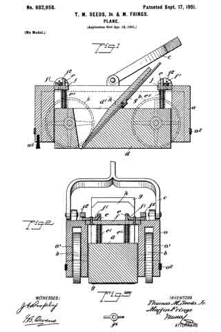
Figure 1 is a longitudinal section of the invention. Fig. 2 is a cross-section thereof; and Fig. 3 is a detail view of one of the dogs, which will be hereinafter described.
a indicates the frame or carriage of the device. This frame is formed with cavities a’
therein, in which are located wheels b, these wheels supporting the frame, andthe cavities a’ being closed at the top to prevent shavings from entering the cavities and clogging the wheels. The frame a has an elastic bead or buffer a2 run around it to prevent marring the woodwork of the building, and at the front portion of the frame is arranged a brush a3, which is adapted to sweep away the dust and other gritty substances prior to the engagement of the blade with the wood.
c indicates the handle, which has a fork at its lower end pivotally connected with the frame a, the handle extending upward within convenient reach of the user, so that the plane may be pushed along much after the manner of the well-known hand lawn-mower.
d indicates a block which is set loosely within the frame a. This block is provided with pins e, which are fastened rigidly thereto and which are projected upward through cross-bars f The cross- bars fare secured rigidly to the frame a by latches f’, which are removably engaged in keepers f2, secured to the frame. Springs e’ bear between the cross-bars f and the block cl and serve to push the block downward. This block cl carries a blade g, which blade is held in the block by a wedge lt. The block d is suitably orificed, as indicated at d’, to receive the blade g and wedge h, so that as the device is moved along the floor the blade in engaging therewith will cut the shavings and throw them into and through the orifice in the block.
The apparatus is adapted to be pushed along on its wheels in the direction desired, and its operation in other respects is very much the same as the usual hand-plane. The block d bears on the ground, and the springs e’ serve to hold the block down, with the blade g properly engaged with the floor. The brush a3 prevents gritty substances from encountering the blade. By manipulating the latches f’ the cross-bars f may be removed from the frame and the block d, with its attached parts, taken out.
Having thus described our invention, we claim as new and desire to secure by Letters Patent —
1. A planer, comprising a wheeled frame, a block movably mounted thereon, means pressing the block downward and a planing-blade held by the block.
2. A planer, comprising a wheeled frame, a block set loosely therein, a spring pressing the block downward, and a planing -blade held by the block.
3. A plane, comprising a wheeled frame, a block mounted loosely therein, a planing-blade held by the block, a cross-bar engaged with the frame, a latch for removably holding the cross-bar in place, and a spring bearing between the cross-bar and block to press the block downward.
In testimony whereof we have signed our names to this specification in the presence of two subscribing witnesses.
THOMAS M. SEEDS, JR.
MARTIN FRINGS.
Witnesses:
NORMAN H. STEVENS,
W. L. STEVENS.


