No. 167,943 – Improvement In Plane-Guides (Walter S. Shipe) (1875)

[paiddownloads id=”254″]167943


UNITED STATES PATENT OFFICE.

_________________

WALTER S. SHIPE, OF MINERVA, OHIO.

IMPROVEMENT IN PLANE-GUIDES.

_________________

Specification forming part of Letters Patent No. 167,943, dated September 21, 1875; application filed August 14, 1875.

_________________

To all whom it may concern:

Be it known that I, WALTER S. SHIPE, of Minerva, in the county of Stark and State of Ohio, have invented an Improvement in Plane-Guides, of which the following is a specification:

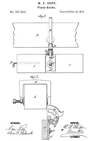
In the accompanying drawing, Figure 1 represents an end view of my improved plane-guide, and Fig. 2 a side view of the same.

Similar letters of reference indicate corresponding parts.

My invention has for its object to so improve the plane-guide for which a patent has been granted to me under date of January 6, 1874, and numbered 146,208, that it will work more steadily and accurately, and be readily set to any desired angle.

The invention consists, mainly, of a recessed handle-extension of the yoke part in connection with a slotted arc-piece of the guide-strip connecting plate, the arc-piece being pivoted to the yoke, and set by a clamp-screw thereto. A wire key with bent end is inserted into a hole of the guide-strip for being readily available for turning the clamping-screw nuts.

In the drawing, A represents a plane, to which the yoke B is attached in the customary manner by a clamping-screw at one end, and flanged side extensions at the opposite end. The yoke B is cast at the end below the flanges with a handle-extension, E, that is centrally recessed tor the slotted arc-piece D, which forms, with its guide-plate D1, the connection with the guide-strip C. The slotted arc D extends at right angles from guide-plate D1, and is inserted and pivoted at its center in the handle-extension E. A set-screw, E’, passes through the perforations of the handle E and the slot of the arc-piece for the purpose adjusting the sliding arc to any required angle. The outer circumference of the arc-piece D is graduated, so that the same may be directly set with the guide-strip C to any required degree of inclination toward the plane. The guide-plate D1 is slotted and adjusted in a recess of the guide-strip C, nearer to, or farther from, the plane by a set-screw, D2. A key, F, of strong wire, with bent end is inserted into a socket-hole of guide-strip C, being slightly curved at its longer part to be retained there in with a certain tension without falling out, the shorter bent end serving as handle to withdraw it from the guide-strip. The wire key F is inserted into perforations of the heads of the set-screws, so that they can be easily loosened or tightened, while the key may be securely put away into the socket-hole of the guide-strip without getting lost. The key is thus always at hand tor use for setting the plane-guide, which is steadily and firmly adjusted in the handle-extension or socket-piece of the yoke.

Having thus described my invention, I claim as new and desire to secure by Letters Patent —

The combination, with a guide-strip, C, of plane-clamping yoke B, having recessed extension E, the pivotted slotted arc-piece D, and the clamp-screw E’, as and for the purpose specified.

WALTER S. SHIPE.

Witnesses:
JOHN BREIDENSTEIN,
A. N. BOORY.

No. 146,208 – Improvement In Plane-Guides (Walter S. Shipe) (1874)

No. 146,208 – Improvement In Plane-Guides (Walter S. Shipe) (1874)

[paiddownloads id=”224″]146208


UNITED STATES PATENT OFFICE.

_________________

WALTER S. SHIPE, OF MINERVA, OHIO.

IMPROVEMENT IN PLANE-GUIDES.

_________________

Specification forming part of Letters Patent No. 146,208, dated December 18, 1874; application filed November 15, 1873.

_________________

To all whom it may concern:

Be it known that I, WALTER S. SHIPE, of Minerva, in the county of Stark and State of Ohio, have invented a new and Improved Plane-Guide, of which the following is a specification:

In the accompanying drawing, Figure 1 represents a sectional end view of my improved plane-guide as applied to a plane. Fig. 2 is a side view of the same 5 and Fig. 3, a detail horizontal section of the wide pivot on the line c c, Fig. 1.

Similar letters of reference indicate corresponding parts.

My invention relates to an improvement in plane-guides by which the plane is steadied in squaring or beveling to any desired angle without the use of a try-square or bevel; and consists of a yoke, which is firmly applied to the plane, and provided, at one end, with a pivoted guide-strip, which is adjusted by clamping-screws under any required angle to the plane.

In the drawing, A represents the plane; B, the yoke; and C, the guide-strip. The yoke B is rigidly applied to plane A by means of a clamp-screw, a, at one side, and a flanged extension, b, at the other side. The guide-strip C is applied to a connecting-piece, D, which is pivoted, by its semicircular part d, to the outwardly-projecting end of yoke B, below flanges b. The semicircular part d is beveled along its circumference, divided by degrees, and rigidly set to any angle to the plane by a curved wedge-piece, e, which is tightly secured between part d and the beveled projection g, at the outer end of yoke B, by a set-screw, f The slotted extension-piece D projects at a right angle to the semicircular part d, and slides in a recess, h, of guide-strip C, so that it may be carried up to the base of the plane, to be firmly secured by a fixed set-screw and washer, l.

When the plan is to be used with the guide for squaring, beveling, or jointing boards, veneers, &c., the yoke is placed over the plane, and firmly screwed thereon in such a manner that the center of the semicircular part d is slightly below the base of the plane. The set-screw at the edge of the are is then loosened, which allows the swinging of the guide-strip to any desired angle. If the angle between the guide-strip and base of the plane is oblique, the set-screw in the slotted part of piece D is loosened, to give greater play to the guide. When the guide is in position, the set-screw and wedge at the arc are tightened, and the guide moved up till it touches the base of the plane. The set-screw of the guide is then tightened on the slotted piece, and the plane ready for use, saving time and labor, and allowing of various applications in the trade.

Having thus described my invention, I claim as new and desire to secure by Letters Patent —

1. The plane-guide consisting of yoke B, with clamping- screw a, pivoted connecting-piece D, curved wedge-piece e, and guide-strip C, with fixed setscrew l, arranged and applied substantially as and for the purposes described.

2. The yoke B, having projecting end, forming the seat of the semicircular part d of piece D, and beveled projecting lug g, as set forth.

WALTER S. SHIPE.

Witnesses:
E. W. POORMAN,
GEO. W. PATTON.