
No. 310,163 – Plane (William F. Achenbach) (1885)
UNITED STATES PATENT OFFICE.
_________________
WILLIAM F. ACHENBACH, OF READING, PENNSYLVANIA.
PLANE.
_________________
SPECIFICATION forming part of Letters Patent No. 310,163, dated January 6, 1885.
Application filed September 15, 1884. (Model.)
_________________
To all whom it may concern:
Beit known that I, WILLIAM F. ACHENBACH, a citizen of the United States, residing at the city of Reading, county of Berks, State of Pennsylvania, have invented a new and useful Improvement in Planes, of which the following is a specification.
This improvement relates more particularly to carpenters’ bench-planes.
The object of the invention is to place in the hands of wood-workers, joiners, and others a plane which will dress smoothly cross-grained and knotty woods so finely that subsequent filling and scraping are rendered unnecessary. These results are attained by a very slight yet important alteration of the mode of dressing the face of planes, as will be explained further on.
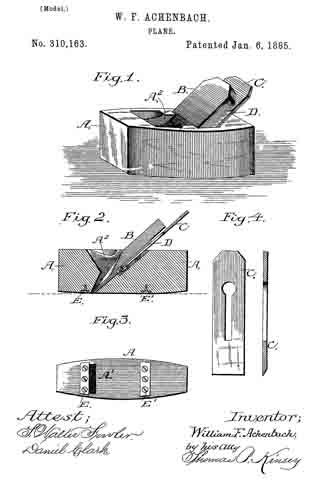
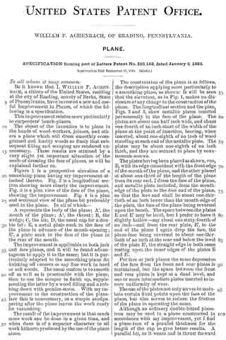
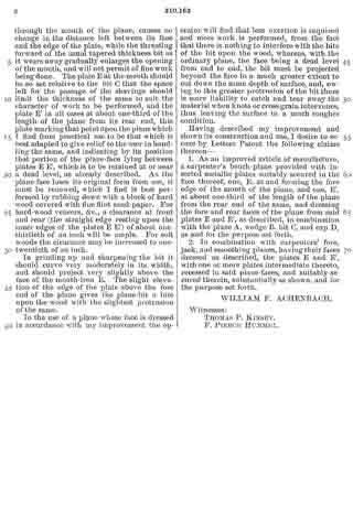
Figure 1 is a perspective elevation of a smoothing-plane having my improvement attached thereto. Fig. 2 is a longitudinal section showing more clearly the improvement. Fig. 3 is a plan view of the face of the plane, showing the improvement. Fig. 4 is a plan and sectional view of the plane-bit preferably used in the plane. In all of which —
A represents the body of the plane; A’, the month of the plane; A2, the throat; B, the wedge; C, the bit; D, the usual cap for a double bit; E, a metal plate sunk in the face of the plane in advance of the mouth-opening; E’, a plate sunk in the face of the plane in the rear of the mouth.
The improvement is applicable to both jack and fore planes, and it will be found advantageous to apply it to the same; but it is particularly adapted to the smoothing-plane for finishing off veneers or any fine work in hard or soft woods. The usual custom is to smooth off as well as is practicable with the plane, then to use the scraper to finish up, supplementing the latter by a wood filling and a rubbing down with pumice-stone. With my improvement in the construction of the plane-face this is unnecessary, as a simple sandpapering after the plane leaves the work ready for varnishing.
The result of the improvement is that much more work can be done in a given time, and when done is of a superior character to all work hitherto produced by the use of the plane alone.
The construction of the plane is as follows, the description applying more particularly to a smoothing-plane, as shown: It will be seen that the elevation, as in Fig. 1, makes no disclosure of any change in the construction of the plane. The longitudinal section and the plan, Figs. 2 and 3, show metallic plates inserted permanently in the face of the plane. The plates are about one-half inch wide, and about one-fourth of an inch short of the width of the plane at the point of insertion, leaving, when inserted, about one-eighth of an inch of wood standing at each end of the metallic plate. The plates may be about one-eighth of an inch thick, and they are secured in place by countersunk-screws.
The plates having been placed as shown, one, E, with its edge coincident with the front edge of the month of the plane, and the other placed at about one-third of the length of the plane from its rear end, I dress the face of the plane, and metallic plate included, from the mouth-edge of the plate to the fore end of the plane, so that the fore end shall be about one-thirtieth of an inch lower than the mouth-edge of the plate, the face of the plane being reversed upon the bench. The space between the plates E and E’ may be level, but I prefer to have it slightly hollow — say about one sixty-fourth of an inch — and from the rear plate, E’, to the end of the plane I again drop the face, the plane-face being reversed to about one-thirtieth of an inch at the rear end below the level of the plate E’, the straight edge in both cases resting upon the inner edges of the plates E and E’.
For fore or jack planes the same depression of the face from the front and rear plates is maintained, but the space between the front and rear plates is kept at a dead level, and one or more intermediate plates inserted to insure uniformity of wear.
The use of the plates not only serves to maintain certain fixed points upon the face of the plane, but also serves to reduce the friction of the plane in operating the same.
Although an ordinary double-bitted plane-iron may be used in a plane constructed in accordance with my improvement, yet I find a plane-iron of a parallel thickness for the length of the cap to give better results. A parallel bit, as it wears and is thrust forward through the mouth of the plane, causes no change in the distance left between its face and the edge of the plate, while the thrusting forward of the usual tapered thickness bit as it wears away gradually enlarges the opening of the mouth, and will not permit of fine work being done. The plate E at the mouth should be so set relative to the bit C that the space left for the passage of the shavings should limit the thickness of the same to suit the character of work to be performed, and the plate E’ in all cases at about one-third of the length of the plane from its rear end, this plate marking that point upon the plane which I find from practical use to be that which is best adapted to give relief to the user in handling the same, and indicating by its position that portion of the plane-face lying between plates E E’, which is to be retained at or near a dead level, as already described. As the plane-face loses its original form from use, it must be renewed, which I find is best performed by rubbing down with a block of hard wood covered with fine flint sand-paper. For hard-wood veneers, &c., a clearance at front and rear (the straight edge resting upon the inner edges of the plates E E) of about one-thirtieth of an inch will be ample. For soft woods the clearance may be increased to one-twentieth of an inch.
In grinding up and sharpening the bit it should curve very moderately in its width, and should project very slightly above the face of the month-iron E. The slight elevation of the edge of the plate above the fore end of the plane gives the plane-bit a bite upon the wood with the slightest protrusion ofthe same.
In the use of a plane whose face is dressed in accordance with my improvement the operator will find that less exertion is required and more work is performed, from the fact that there is nothing to interfere with the bite of the bit upon the wood, whereas, with the ordinary plane, the face being a dead level from end to end, the bit must be projected beyond the face to a much greater extent to cut down the same depth of surface, and, owing to this greater protrusion of the bit there is more liability to catch and tear away the material when knots or cross grain intervenes, thus leaving the surface in a much rougher condition.
Having described my improvement and shown its construction and use, I desire to secure by Letters Patent the following claims thereon —
1. As an improved article of manufacture, a carpenter’s bench-plane provided with inserted metallic plates suitably secured in the face thereof, one, E, at and forming the fore edge of the mouth of the plane, and one, E’, at about one-third of the length of the plane from the rear end of the same, and dressing the fore and rear faces of the plane from said plates E and E’, as described, in combination with the plane A, wedge B. bit C, and cap D, as and for the purpose set forth.
2. In combination with carpenters’ fore, jack, and smoothing planes, having their faces dressed as described, the plates E and E’ with one or more plates intermediate thereto, recessed in said plane-faces, and suitably secured therein, substantially as shown, and for the purpose set forth.
WILLIAM F. ACHENBACH.
Witnesses:
THOMAS P. KINSEY,
F. PIERCE HUMMEL.