No. 161,516 – Improvement In Bench-Planes (William Johnstone) (1875)

UNITED STATES PATENT OFFICE.
_________________
WILLIAM JOHNSTONE, OF MONTREAL, CANADA, ASSIGNOR OF ONE-HALF HIS RIGHT TO WILLIAM WHITEHEAD ROBERTSON, OF SAME PLACE.
IMPROVEMENT IN BENCH-PLANES.
_________________
Specification forming part of Letters Patent No. 161,516, dated March 30, 1875; application filed March 1, 1875.
_________________
To all whom it may concern:
Be it known that I, WILLIAM JOHNSTONE, of the city and district of Montreal, in the Province of Quebec, in the Dominion of Canada, pattern-maker, have invented an Improvement on Bench-Planes, of which the following is a specification:
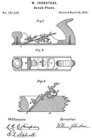
My invention relates to the adjustment of the plane-iron by means of a nut working on a screw, so that by simply turning the nut the plane-iron is drawn into or pushed out irom the body of the plane, and when at the desired place is held there firmly by a catch in the shape of an eccentric or cam, reference being had to the annexed drawings, where similar letters indicate like parts, and where —
Figure 1 represents a sectional elevation of an iron plane embodying my invention. Fig. 2 represents a plan of Fig. 1. Fig. 3 represents a modification adapting it to wooden planes.
Letter A is the body of the plane, having two cross-bars or partitions, B B, formed in it, extending up to the under side of the plane-iron C, and of such height that the plane-iron is supported at the proper angle. In the bars B B, and extending from one to the other, is fixed, by any suitable means, a screw, D, on which is a flat nut, E, having its edge milled to adord a better hold and prevent the fingers or thumb of the person using it from slipping. This nut E passes through the slit F in the plane-iron C, and projects a short distance beyond it. The plane-iron C is held fast by the cam G. This cam is turned on the pin h by means of the handle i, and when in the position shown in the drawings by firm lines the projecting part k presses tight on the plane-iron C, and holds it firmly against the bars B B and the beveled edge of the hole l.
When it is desired to adjust the plane-iron the cam G is thrown up into the position shown by the dotted lines in Fig. 1. The plane-iron C is now free to be moved, which is done by placing the thumb or finger on the projecting part of the nut E and turning it round. This causes it to move up or down the screw D, and its side being in contact with the side of the slit F in the plane-iron C compels it to move in the same direction with it. When in the required position the cam G is turned down and holds it there.
The plane-iron C is provided with one or more additional slits, F’, to be used when it becomes shorter by the wearing away of its cutting-edge.
The modification shown in Fig. 3 consists of the piece H, of any suitable configuration, firmly secured to the wooden body of the plane in place of the bars B B to carry the screw D;
the remainder of the parts being the same as above described in connection with planes having bodies of iron, with the exception that a passage is cut through the projecting part k of the cam G, to allow the nut n. to pass when the plane-iron C is worn short.
By these arrangements I am enabled to adjust the plane-iron with greater nicety, and more easily and expeditiously than by the old method.
What I claim as my invention is —
The plane A, having bars B B, in combination with screw D, nut E, and plane-iron C, having slits F and F’, substantially as and for the purposes described.
WILLIAM JOHNSTONE.
Witnesses:
C. G. C. SIMPSON,
E. L. STILWELL.


