
No. 112,062 – Improvement In Carpenters’ Planes (William Miller) (1871)
United States Patent Office.
WILLIAM MILLER, OF BOSTON, MASSACHUSETTS, ASSIGNOR TO HIMSELF
AND C. E. WOODMAN, OF SAME PLACE.
Letters Patent No. 112,062, dated February 21, 1871.
_________________
IMPROVEMENT IN CARPENTERS’ PLANES.
_________________
The Schedule referred to in these Letters Patent and making part of the same.
_________________
I, WILLIAM MILLER, of Boston, in the county of Suffolk and State of Massachusetts, have invented certain Improvements in Planes, of which the following is a specification.
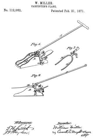
Figure 1 is a perspective view of my invention;
Figure 2 is a side elevation of’ the same; and
Figure 3, a detached view of a modification.
The object of this invention is to enable a carpenter’s plane to be operated at a greater distance from the workmen than the length of his arm, as in planing floors, ceilings, &c.; and It consists of a metallic yoke, pivoted to the plane, and provided with rollers and a projecting finger, and pivoted to a long staff or handle, as will hereinafter more fully appear.
In the drawing —
A represents the plane, on the side of which are the vertical flanges B.
C represents a yoke, which is pivoted to the flanges B by screws D.
The upper portion of yoke C is provided with lugs E and projection F, to the latter of which is attached a spring or finger, H.
The ends of yoke C are provided with rollers, I.
J represents a long handle or staff, which is pivoted at one end to lugs E.
When a forward motion is imparted to the plane A through handle J, the upper portion of yoke C is pushed forward, causing the finger H to bear firmly downward on the forward portion of the plane A, as shown in fig. 1, which places rollers I in such position that their lower edges are flush with the bottom of plane A. The plane is thus caused to operate as effectively as if in the hands of the workman, the finger H holding the foremost end down to its work, which finger, being slightly elastic, does not hold it too firmly.
The plane being drawn backward, the finger H is lifted from the plane, and the rollers I are brought downward until one side of yoke C comes in contact with the projecting pin m, which holds the same in the position shown in fig. 2, the rollers I projecting below the plane A, and slightly raising the same as it is being drawn backward, and protecting the cutting-iron when not in use.
The finger H may be bifurcated, as shown in fig. 3, the bifurcations H’ resting on the flanges B, thereby preventing the shaving from becoming clogged.
Having thus fully described my invention,
What I claim as new, and desire to secure by Letters Patent is —
1. The combination of plane A, yoke C, and rollers I, substantially as described.
2. The combination of plane A, yoke C, rollers I, and single or bifurcated finger H, substantially as described.
3. The combination of plane A, yoke C, rollers I, finger H, and staff or handle J, substantially as described.
In testimony whereof I have signed my name to this specification in the presence of two subscribing witnesses.
WILLIAM MILLER.
Witnesses:
CARROLL D. WRIGHT,
CHARLES F. BROWN.