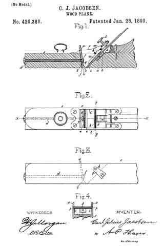
No. 439,061 – Bench-Plane (Jerome E. Greene) (1890)

[paiddownloads id=”467″]439061


UNITED STATES PATENT OFFICE.

_________________

JEROME E. GREENE, OF TOCCOA, GEORGIA, ASSIGNOR
OF ONE-THIRD TO JOHN McJUNKIN, OF SAME PLACE.

BENCH-PLANE.

_________________

SPECIFICATION forming part of Letters Patent No. 439,061, dated October 21, 1890.
Application filed November 30, 1889. Serial No. 332,142. (No model.)

_________________

To all whom it may concern:

Be it known that I, JEROME E. GREENE, a resident of Toccoa, in the county of Habersham and State of Georgia, have invented certain new and useful Improvements in Roller Bench-Planes; and I do hereby declare the following to be a full, clear, and exact description of the invention, such as will enable others skilled in the art to which it pertains to make and use the same.

The object of my invention is to improve the efficiency of bench-planes and to provide simple and durable devices for adjusting and holding the bit, that can be quickly and conveniently operated; and it consists in the matters hereinafter described and pointed out.

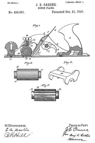
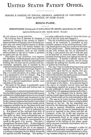
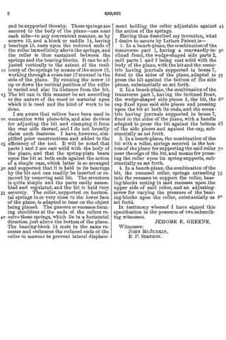
In the accompanying drawings, Figure 1 is a vertical longitudinal section on line a b. Fig. 2 is a side elevation of a roller, and Fig. 3 is a perspective view of a detail. Fig. 4 is a side elevation of a corrugated roller. Fig. 5 is a partial section on line c d of Fig. 1, and Fig. 6 is a partial longitudinal section near one side of the plane.

The body of the plane is preferably made of metal having the side and bottom cast in one piece.

A cross-piece 1, situated just behind the location for the bit, may be cast with the other parts, and also two wedge-shaped pieces 2, one on each side. A handle, which may be secured to the body in any convenient manner, is denoted by 3.
In the present instance the handle is provided in its lower end with an undercut recess, which engages a suitable lug on the plane-body and is then fastened in such position by a screw, as indicated in Fig. 1. A bit is indicated by 4. It is placed on the inclined front side of the support 1 and beneath the side parts 2. The latter at their lower extremities are reduced to a thin edge and receive above them a cap or plate 5, which is conveniently secured to the parts 2 by screws. The part 1 strengthens the plane-body. It also supports the bit at its lower part in a horizontal direction, the slipping of the bit in an approximately vertical direction being prevented by a locking or clamping device which forces the bit against suitable bearings. The spring 5 is made sufficiently strong to force the lower end of the bit upon said support 1.

The bit is locked in any desired position by means of an eccentric 6, journaled in any suitable manner, as by securing-bones 7, having bearings for a rod, bar, or pin 8 to the sides of the plane-body. These bearings are open on the side toward the bit, as indicated in in Fig. 1, and permit the rod 8 with the cam to be inserted or removed when desired by suitably turning them and taking out the bit, if necessary. A handle 9 affords means for suitably moving the eccentric, the bit being released by raising the handle, and gripped or locked by lowering it.

The cap 5 can be made of spring metal, and being prolonged beyond the bearings 2 and bent down upon the bit, as shown, will produce a spring-pressure upon the same. To relieve this tension, the spring-plate is released by loosening its retaining-screws.

As illustrated in Fig. 1, the cap is in close contact with its supports 2 throughout the entire length of the latter. It is obvious that if the cap is of suitable curved form and the compression applied by means of the screws is just sumcient to bend it down upon supports 2 they will appear as represented in Fig. 1.

In Fig. 6 an enlarged view is shown, indicating a small space between the cap and support, which could not be well indicated in Fig. 1. The cap at its lower end has a knife-edge, it being essential that it have a closely-fitted bearing on the bit. By the described construction the fastening together of a bit and its cap in manner heretofore practiced is avoided and the bit can be independently removed or inserted in the plane, and the adjustment of the bit to the cap requires no special attention, for the reason that the cap is permanently fixed in its proper position and the proper adjustment of the bit with reference to the bottom of the plane necessarily secures a suitable adjustment with respect to the cap.

In front of the bit is arranged a roller 10, which is preferably corrugated and is provided with circumferential shoulders 11, forming recesses adapting it to receive springs and be supported thereby. These springs are secured to the body of the plane — one near each side — in any convenient manner, as by screws 13, and a block or saddle 14, having bearings 15, rests upon the reduced ends of the roller immediately above the springs, and the roller is thus sustained between the springs and the bearing-blocks. It can be adjusted vertically to the extent of the resiliency of the springs by means of the screw 16, working through a cross-bar 17 secured in the side of the plane. By running the screw 16 up or down the vertical position of the roller is varied and also its distance from the bit. The bit can in this manner be set according to the nature of the wood or material upon which it is used and the kind of work to be done.

I am aware that rollers have been used in connection with plane-bits, and also devices for adjusting the bit and clamping it from the rear side thereof, and I do not broadly claim such features. I have, however, simplified prior constructions and added to the efficiency of the tool. It will be noted that parts 1 and 2 are cast solid with the body of the plane, and that the spring-plate bears upon the bit at both ends against the action of a simple cam, which latter is so arranged and supported that it is held in its bearings by the bit and can readily be inserted or removed by removing said bit. The structure is quite simple and the parts easily assembled and regulated, and the bit is held very securely. The roller, supported on horizontal springs in or very close to the lower face of the plane, is adapted to bear on the object being planed. The grooves or recesses forming shoulders at the ends of the rollers receive these springs, which lie in a horizontal direction just above the bottom of the plane. The bearing-block 14 rests in the same recesses and embraces the reduced ends of the roller in manner to prevent lateral displacement holding the roller adjustable against the action of the springs.

Having thus described my invention, what I desire to secure by Letters Patent is —

1. In a bench-plane, the combination of the transverse part 1, having a rearwardly-inclined front, the wedge-shaped side parts 2, said parts 1 and 2 being cast solid with the body of the plane, with the bit and the eccentric having journals supported in boxes 7, fixed to the sides of the plane, adapted to press the bit against the bottom of the side pieces, substantially as set forth.

2. In a bench-plane, the combination ofthe transverse part 1, having the inclined front, the wedge-shaped side pieces 2, the bit, the cap fixed upon said side pieces and pressing upon the bit at both its ends, and the eccentric having journals supported in boxes 7, fixed to the sides of the plane, with a handle adapted to press the bit against the bottom of the side pieces and against the cap, substantially as set forth.

3. In a bench-plane, the combination of the bit with a roller, springs secured in the bottom of the plane for supporting the said roller near the edge of the bit, and means for pressing the roller upon its spring-supports, substantially as set forth.

4. In a bench-plane, the combination of the bit, the recessed roller, springs extending into the recesses to support the roller, bearing-blocks resting in said recesses upon the upper side of said roller, and an adjusting-screw for varying the pressure of the bearing-blocks upon the roller, substantially as set forth.

In testimony whereof I have signed this specification in the presence of two subscribing witnesses.

JEROME E. GREENE.

Witnesses:
JOHN McJUNKIN,
E. P. SIMPSON.

No. 435,951 – Bench-Plane (Arthur E. Rust) (1890)

[paiddownloads id=”466″]435951


UNITED STATES PATENT OFFICE.

_________________

ARTHUR E. RUST, OF PINE MEADOW, CONNECTICUT,
ASSIGNOR OF ONE-HALF TO SOLON R. RUST, OF SAME PLACE.

BENCH-PLANE.

_________________

SPECIFICATION forming part of Letters Patent No. 435,951, dated September 9, 1890.
Application filed July 29, 1889. Serial No. 319,130. (No model.)

_________________

To all whom it may concern:

Be it known that I, ARTHUR E. RUST, a citizen of the United States, residing at Pine Meadow, in the county of Litchfield and State of Connecticut, have invented certain new and useful Improvements in Bench-Planes; and I do hereby declare the following to be a full, clear, and exact description of the invention, such as will enable others skilled in the art to which it appertains to make and use the same.

My invention relates to improvements in bench-planes in which the bit is adjusted by means of a lever; and the objects of my improvement are, first, to provide a means of adjusting the bit of a bench-plane longitudinally, making it cut the thickness desired, and, second, to adjust the bit laterally, thus squaring the cutting-edge of the bit with the face of the plane. Both objects are attained by the movement of one lever either longitudinally or laterally, each motion being independent of the other, as illustrated in the accompanying drawings, in which —

Figure 1 is a side elevation. Fig. 2 is same as Fig. 1, being partially in section. Fig. 3 is a view of the adjusting-lever, showing its bearing on the pin, and is also partially in section.

Similar letters refer to similar parts throughout the several views.

The body of the plane A is similar to that of other planes, and to it is secured a frame B, having an upward extension to receive the screw D and form a bearing or support for the pin F, upon which is pivoted a lever C in such a manner as to allow the lever C to he moved laterally as well as on the pin F as a pivot. Thus the lever C may be given either of two motions upon one bearing or pin F. The lever C is provided with three extensions G, H, and I. The extension I passes through a slot in the bit J and through the hole a in the cap-plate K, as shown in Fig. 2, so that when the screw D is turned or screwed into the threaded hole in the casting B one end of the screw D will bear against the extension H and move the lever C, which will move the cap-plate K and bit J, making the cutting-bit cut a thicker shaving, or if the screw D be turned the other way or unscrewed the lower end of the screw D will bear against the extension G, thus moving the cap-plate K and the bit J up, so that the bit J will cut a thinner shaving. If the cutting-edge of the bit is not square with the face of the plane, it may be made so by moving the lever C laterally in the direction required.

What I claim as new, and desire to secure by Letters Patent, is —

In a bench-plane, the herein-described mechanism for adjusting the cutting-bit longitudinally or laterally, consisting of a lever one end of which (being the upward extension) passes through a slot in the bit and through a hole in the cap-plate, this lever being so made and pivoted in a suitable supporting-frame as to allow the other end or downward extension to be moved in either of two directions upon one pivot or fulcrum to adjust the cutting-bit longitudinally or laterally, substantially as shown and described, for the purpose specified.

In testimony whereof I affix my signature in presence of two witnesses.

ARTHUR E. RUST.

Witnesses:
AMIE S. JEWELL,
FREDERICK A. JEWELL.

No. 435,789 – Bench-Plane Attachment (Thomas W. Bartholomew) (1890)

[paiddownloads id=”465″]435789


UNITED STATES PATENT OFFICE.

_________________

THOMAS W. BARTHOLOMEW, OF DANVILLE, PENNSYLVANIA.

BENCH-PLANE ATTACHMENT.

_________________

SPECIFICATION forming part of Letters Patent No. 435,789, dated September 2, 1890.
Application filed December 18, 1889. Serial No. 334,188. (No model.)

_________________

To all whom it may concern:

Be it ltnown that I, THOMAS W. BARTHOLOMEW, of Danville, in the county of Montour and State of Pennsylvania, have invented certain new and useful Improvements in Bench-Plane Attachments; and I do hereby declare that the following is a full, clear, and exact description of the invention, which will enable others skilled in the art to which it appertains to make and use the same, reference being had to the accompanying drawings, and to the letters of reference rnarked thereon, which form part of this specification.

My invention relates to certain improvements in bench-plane attachments.

The object of the invention is to provide an improved attachment for planes to fit into the angle between the plane-iron and plane body or stock and prevent the hand when using the plane from pushing against the plane-iron, and thereby protect the hand from the sharp edges of said iron.

These objects are accomplished by and my invention consists in certain novel features of construction and in combinations of parts more fully described hereinafter, and particularly pointed out in the claims.

Referring to the accompanying drawings, Figure 1 is a side elevation of a bench-plane provided with the present attachment or hand-guard. Fig. 2 is a rear view of the same. Fig. 3 is a detail perspective of the hand-guard. Fig. 4 is a detail bottom plan of the same. Fig. 5 is a detail of the cushion for the guard. Fig. 6 is a section on plane of line x x, Fig. 2.

In the drawings, the reference-letter a indicates the body or stock of a plane provided with a plane-iron b and a wedge c, as usual.

When using bench-planes of the characteristics shown, the plane-stock is grasped by the right hand just in rear of the plane-iron, and as the plane is reciprocated the tender portions of the hand between the thulnb and first linger press and rub against the sharp edges of the iron and bit, and are thereby injured, blistered, and rendered exceedingly sore and uncomfortable, and, further, it is difficult to obtain a good hold of the stock of the plane. In order to obviate these disadvantages, a hand-guard d is secured and fitted in the angle between the upper face of the stock and the iron. This guard is hollow and formed integral of cast or sheet metal, provided with the fiat base e, formed by an inwardly-extending flange having opposite transverse apertures f to receive the securing-screws g’, from which base the guard extends upwardly and rearwardly and is rounded at its top, the edges thereof fitting against the rear face of the iron and inclined upwardly at an acute angle equal to the angle of the iron. The rear outer rounded side of the guard is formed so as to fit in the space between the thumb and first linger, and on the right-hand side this guard is provided with a depression It to receive the main thumb-joint. The rear or heel portion of the base of the guard is provided in its under face with a depression or socket i to receive and hold a cushion j, of leather or other suitable substance, fitting between the guard and plane-stock, and the under face of the base is provided with a pair of downwardly-projecting lugs j’ j’ at opposite ends of the said socket. These lugs serve as rests or feet and prevent the guard from being screwed down too tightly or unevenly, and also serve as guards to prevent the cushion being scraped or knocked from its place. The object of this leather cushion is to give the guard an elastic bearing, raise it up, and prevent it from breaking from the jar caused by striking the plane to loosen the plane-iron. The cushion j can be secured in its socket by any suitable material, such as glue, &c. Of course it is understood if the wedge c is placed beneath the bit or iron the guard will iit beneath the same in a like manner.

The great utility and advantages of this article are obvious and well understood, and the article can be manufactured and sold and applied to any plane.

What I claim is —

1. As a new article of manufacture, the herein-described hollow hand-guard for bench-planes, formed integral and consisting of a base to fit on the upper face of the plane-stock, provided with apertures for the securing-screws and with a socket and feet on its under face, for the purposes set forth, and an upwardly and rearwardly inclined portion to fit against the rear side of the plane-iron, formed on its rear side to iit the hand, substantially as described.

2. The herein-described hand-guard for planes, formed integral, consisting of a base to fit on and be secured to the stock, and provided with one or more feet to bear on the stock and an upwardly-extending portion inclined rearwardly and rounded on its outer side to fit the hand, substantially as described.

3. The herein-described hand-guard for planes, consisting of a base having perforations for the securing-screws and provided near its heel with a socket to receive a cushion and with feet located on opposite sides of said socket, and the portion extending upwardly from the base, having inclined edges and formed at its rear side to fit the hand, substantially as described.

4. The combination, with a plane-stock and plane-iron, of a hand-guard secured and fitted in the angle between the upper face of the stock and the plane-iron and rounded on its outer side to fit the hand and a cushion interposed between the stock and said guard, substantially as described.

5. The combination of a plane with a hollow integral metal hand-guard therefor, having a base secured to the stock and a cushion located between said base and stock to tilt said guard and prevent breakage of the guard by striking the plane-stock, substantially as described.

6. In a plane, the combination of a stock with a hand-guard formed hollow and integral and having a base secured to the upper face of the stock, a portion rounded at its rear and extending upwardly and fitting against the rear face of the plane-iron, and a cushion interposed between the base of said guard and the stock and resting in a socket, for the purposes set forth.

In testimony that I claim the foregoing as my own I affix my signature in presence of two witnesses.

THOS. W. BARTHOLOMEW.

Witnesses:
ROBERT ADAMS,
THOS. J. MILES.

No. 434,361 – Plane (Ole O. Skattebo) (1890)

[paiddownloads id=”464″]434361


UNITED STATES PATENT OFFICE.

_________________

OLE O. SKATTEBO, OF HANNAFORD, NORTH DAKOTA,
ASSIGNOR OF ONE-HALF TO JORGEN HANSON, OF SAME PLACE.

PLANE.

_________________

SPECIFICATION forming part of Letters Patent No. 434,361, dated August 12, 1890.
Application filed March 8, 1890. Serial No. 343,098. (No model.)

_________________

To all whom it may concern:

Be it known that I, OLE O. SKATTEBO, of Hannaford, in the county of Griggs and State of North Dakota, have invented a new and Improved Plane, of which the following is a full, clear, and exact description.

My invention relates to improvements in carpenters’ planes; and the object of my invention is to provide a plane that will be equally efficient as a square or bevel plane, and that may be readily converted from one to the other, and also to provide a plane in which a great variety of tools may be inserted, so that the plane maybe used for matching, rabbeting, grooving, rounding, beading, and the like.

To this end my invention consists in a plane constructed substantially as hereinafter described and claimed.

Reference is to be had to the accompanying drawings, forming a part of this specification, in which similar letters of reference indicate corresponding parts in all the figures.

Figure 1 is a plan view of the plane; Fig. 2, a side elevation of the same with a portion of the guide-plate broken away; Fig. 3, an end view of the device as adjusted for a square plane, but with the guide-strip removed; Fig. 4, an end view of the same adjusted for a bevel-plane; Fig. 5, an end view of the plane adjusted for rabbet-work; Fig. 6, a side elevation of one of the separable parts of the plane with a portion of one hinge in section; Fig. 7, a detailed view of the pintle of the plane-hinges; Figs. 8 and 9, side elevations of the strips used for matching and rabbeting; Fig. 10, a transverse section on the line x x, of Fig. 8; Fig. 11, a detail view in elevation of the grooving-knife; Fig. 12, a perspective view of the grooving-guide; Fig. 13, a perspective view of the rounding or molding guide; Fig. 14, a front elevation of a corresponding knife for same, and Fig. 15 a perspective view of a ripping-guide.

The body or frame of the plane consists of two longitudinally-separable parts A and B, which are so hinged together by hinges a, near the ends thereof, that they may be placed at various angles with each other. The hinges a are attached to the inner edge of the part A, which carries the planer-knives, and to the upper edge of the part B, so that when the parts are shut closely together, the part B will shut against theinner edge of the part A, so as to project downwardly at right angles with the same. The hinges a are also provided with a removable pintle b, which fits in the knuckles a’ of the hinges, and which is screw-threaded at the end to engage a similar thread upon the interior of the inner knuckle of the hinges, so that the pintle may be easily removed and the parts A and B of the frame separated.

The parts A and B are each provided with a suitable handle A’ B’, by which the plane may be pushed or pulled, as the case may be, and with upwardly-extending braces A2 and B2, which fit closely together, and which are provided with corresponding holes d, through which extend the curved arms D or straight arms D’, said arms being attached to the braces B2 by the screws e, which fit a screw-thread in the ends of said arms, and being retained in the braces A2 by the binding-screws f which project through from the top of said braces and impinge upon said arms, so that the parts A and B are adjustably connected by the arms D and D’ and their attaching-screws.

In order that there may be no movement whatever between the parts A and B when adjusted by the straight bars, I provide other openings d’ below and between the upper openings d, one of said openings d’ being shown in Fig. 2 and 5. The lower bar D’ passes through said opening d’.

The part A of the frame is provided with the usual slide E, in which a knife F is inserted, with a set-screw g, which projects through the slide and holds the knife in position therein, and with a slot E’, through which the knife extends below the bottom of the plane. The part A is also provided upon the bottom with a longitudinal groove or recess H, which extends the entire length thereof, in which the various guides are inserted, as hereinafter described, and with screws h, which project through the wall of said groove, by means of which the guides are retained in the groove.

Attached to the inner side of the part B is the vertically-adjustable guide-plate J, which is of the same length as the part B and extends below the lower edge thereof. It serves as a guide to the plane, and is attached to the part B of the frame by the screws i, which project through vertical slots j in the plate into the side of the part B, so that by loosening said screws the plate may be easily adjusted upon the frame.

When a square edge is to be planed, the parts A and B of the frame are locked together, so that they will be at right angles with each other, as best shown in Fig. 3, and the plane is used as an ordinary square-edge plane. When a beveled edge is to be planed, the curved arms D are inserted in the holes d, and the parts are swung apart upon their hinges till the desired bevel is obtained, when they are retained in this position by tightening the binding-screws f upon the arms D. This position is best shown in Fig. 4. The plane is then used as an ordinary bevel-plane. To facilitate the adjustment to any bevel, the curved arms D should be marked off into degrees, and then when the proper degree is indicated upon the arms they may be secured in position as desired.

If the plane is to be used as a matching-plane, the guide-strips K and K’, which are of about the width of the groove to be planed, are inserted in the groove H in front of and behind the slot E’. A suitable narrow knife is inserted in the slide E so as to project down between the guide-strips K and K’, and the plane is used as an ordinary matching-plane. If a tongue is to be cut, the guide-strips K and K’ are removed and a suitable knife for tongue-planing inserted in the slide E.

If the plane is to be used as a rabbet-plane, the curved arms are removed from the holes d and the straight arms D’ inserted, the pintle b is removed from the hinges a, and the plane will then be laterally adjustable. The arms D’ are held in a desired position by the binding-screws f in the same way that the arms D are secured, and the arms should be marked off into fractions of an inch, that they may be easily adjusted. The guide-strip K’ and the guide-strip K, which is provided with a vertically-adjustable knife l, which is attached thereto by a screw m, projecting through a slot l’ thereof, are inserted in the groove H and held by the screws h. A suitable knife is inserted in the slide E, and the plane is ready for rabbet-work. In using it as a rabbet-plane and for other similar work the distance of the knife from the edge of the board is regulated by the arms D’ and binding-screws f as the part B of the frame, which extends down the side of the board, may be brought as near to the part A as desired, and is secured in that position, as described. When used for rabbet-work, the knife l will project a desired distance below the guide-strip K, and, entering the board to be planed, will cut a smooth surface for the shoulder of the rabbet.

In Figs. 11 and 12 I have shown a knife and guide for grooving. The guide L is provided with an upwardly-projecting tongue L’, which fits into the groove H of the plane, is held therein by the screws h, and is provided with a rounding lower face corresponding with the groove to be planed. The knife L2 has a convex edge corresponding to the shape of the lower surface of the guide L. It is inserted in the slide E of the plane in the usual manner, and the plane is used as an ordinary grooving-plane.

In Figs. 13 and 14 I have shown a knife and guide for rounding or molding. The guide M is provided with a tongue M’ which fits the groove H, and which is used in the same way as the grooving-guide. The rounding-guide, however, is provided with a concave lower surface and the plane with a corresponding knife M2, having a concave cutting-edge.

When the plane is to be used as a ripping-plane, the ripping-guide N, having a narrow edge N’, is secured in the groove H, a suitable ripping-knife is inserted in the slide E, and the plane is used as a ripping-plane.

I might show many more tools that could be used with the plane; but without going further into details it is evident that by making a suitable guide to fit the groove H and providing a corresponding knife the plane may be used to produce almost any form.

It will be seen from the foregoing description that a person by having a plane as described, with the accompanying guides and knives, can do the work now performed by a great many separate planes.

Having thus described my invention, what I claim as new, and desire to secure by Letters Patent, is —

1. A plane consisting in a stock or knife-carrying portion, a longitudinal guide adapted to be held parallel with or at any desired angle to the said stock, a separable hinge-joint to connect the two parts when the guide is to be held at an angle, and interchangeable rods and set-screws for holding the guide parallel with or at an angle to said stock, substantially as set forth.

2. A plane consisting, essentially, of two longitudinally-separable parts, the knife-carrying part having a longitudinal slot in the bottom thereof, in which any desired form of guide maybe inserted, and having a suitable slide in which a knife may be secured to match said guide, substantially as described.

3. The combination, with the plane A B, the part A having a longitudinal groove in the bottom thereof, as shown, of the rabbet-guide K, adapted to fit in said groove, and having a vertically-adjustable knife l affixed thereto to cut the shoulder of the rabbet, substantially as described.

OLE O. SKATTEBO.

Witnesses:
MARTIN MOSSING,
ERIK AUSTAD.

No. 426,806 – Plane (Edmund P. Hann) (1890)

[paiddownloads id=”463″]426806


UNITED STATES PATENT OFFICE.

_________________

EDMUND P. HANN, OF PORTLAND, INDIANA, ASSIGNOR OF
ONE-HALF TO WILLIAM S. BAKER, OF SAME PLACE.

PLANE.

_________________

SPECIFICATION forming part of Letters Patent No. 426,806, dated April 29, 1890.
Application filed December 14, 1889. Serial No. 333,744. (No model.)

_________________

To all whom it may concern:

Be it known that I, EDMUND P. HANN, a citizen of the United States, residing at Portland, in the county of Jay and State of Indiana, have invented certain new and useful Improvements in Planes; and I do declare the following to be a full, clear, and exact description of the invention, such as will enable others skilled in the art to which it appertains to make and use the same.

This invention has relation to an improvement in planes; and it has for its object to provide means whereby the cut may be regulated without moving the bit and without the employment of springs and levers or other like objectionable devices.

The invention will be fully understood from the following description and claims, when taken in connection with the annexed drawings, in which —

Figure 1 is a longitudinal sectional view of a plane constructed according to my invention, and Fig. 2 is a perspective view of the follower removed from the stock.

Referring to said drawings by letter, A indicates the stock, which may be mainly of any ordinary or approved construction and provided with a suitable handle B. The forward portion of the stock and in advance of the throat thereof is provided with a chamber, which is inclosed by the longitudinal side plates or walls of the stock, and also the forward transverse wall thereof. The body of the stock is provided at its forward end with a beveled seat a to seat the bit and the iron for securing the same in position.

The bit C is provided with the usual elongated slot b for adjusting the same; but, as will presently appear, such slot is only needed at first placing the bit after it has been removed for repairs or the replacement of a new one.

Secured transversely in advance of the throat d and to the side walls of the stock is a cross bar or block D, which is provided with an aperture e and serves as a bearing for one end of a cam-shaft, as will be presently explained. The forward transverse end wall f of the stock is also provided at a corresponding point with a similar aperture g to receive the forward or opposite end of said cam-shaft.

E indicates what I shall denominate the “follower.” This follower is provided with a truly planed engaging-face corresponding with the engaging-face of the main body of the stock and is arranged in the chamber or recess F. This follower may consist of a block, as shown, having a longitudinal recess in its upper face, as N, to receive the cam-shaft G, and across the opposite ends of this recess are strips i, which may be of metal or other suitable material. These strips are designed to furnish bearings for the cam-shaft, and the recess is preferably covered by a plate H or the like.

G indicates the cam-shaft. This shaft, which is designed to raise and lower the follower, has its opposite ends extended therefrom, as shown at l, and bear, respectively, in the aperture of the cross-bar D and the aperture in the forward transverse wall of the stock. These journal ends being arranged at corresponding points and eccentrically on the opposite ends of the shaft G, it will be seen that by simply turning the shaft the follower may be raised or lowered, as desired. By arranging the cam-shaft horizontally and causing it to exert its force transversely the follower can be raised or lowered evenly at all points by a single cam and without having to place any objectionable lugs or other attachments on the top or bottom of the plane-stock, and it also permits of a hand-wheel or other means of rotating it being placed on the forward end of the stock out of the way. The forward end of this shaft is provided with a small hand-wheel I for turning the same and manipulating the follower.

In operation it will be seen that when the bit has been set with respect to the lower face of the main body of the stock and it is desirable to get a cut of less depth it is simply necessary to turn the cam-shaft by the hand-wheel until the follower has been lowered to the desired point. To increase the depth of the cut the operation is simply reversed.

With a plane of this character it will be seen that there is little or no chance for lateral deviation of the cutter, as when once set it remains so, as the adjusting of the cut is performed by the follower and the manipulating cam-shaft.

While I have described minutely the parts in the exact construction and combination as illustrated, yet I do not wish to be understood as confining myself to such, as it is obvious that the object in view might be arrived at by other devices such as would suggest themselves to a skilled mechanic. It is necessary, however, that a cam and also a follower be used.

Having described my invention, what I claim is —

1. A plane having a practically fixed bit, in combination with a follower arranged in advance thereof and a rotatable cam-shaft having its axis arranged horizontally and exerting its pressure transversely thereto for raising and lowering said follower, substantially as specified.

2. The combination, with a stock having a I chamber in advance of the throat, a cam-shaft jonrnaled therein and adapted to exert pressure transversely to its axis of rotation, and carrying a hand-wheel on one end, of a follower suspended on said shaft and adapted to be raised and lowered thereby, substantially as specified.

3. The combination, with the stock, of the vertically-movable follower, the cam-shaft bearing in said follower, and bearings in the stock for receiving the opposite ends of the shaft, substantially as specified.

In testimony whereof I affix my signature in presence of two witnesses.

EDMUND P. HANN.

Witnesses:
WILLIAM S. BAKER,
DAVID V. BAKER.

No. 426,636 – Plane-Bit (Henry Condron) (1890)

[paiddownloads id=”462″]426636


UNITED STATES PATENT OFFICE.

_________________

HENRY CONDRON, OF CHICAGO, ILLINOIS, ASSIGNOR OF
ONE-HALF TO WILLIAM H. BARRY, OF SAME PLACE.

PLANE-BIT.

_________________

SPECIFICATION forming part of Letters Patent No. 426,636, dated April 29, 1890.
Application filed February 10, 1890. Serial No. 339,795. (No model.)

_________________

To all whom it may concern:

Be it known that I, HENRY CONDRON, of Chicago, in the county of Cook and State of Illinois, have invented certain new and useful Improvements in Plane-Bits, of which the following is a full, clear, and exact description, reference being had to the accompanying drawings, forming a part of this specification, in which —

Figure 1 is a perspective view of a plane-bit embodying the features of my invention. Fig. 2 is a front view of the same, and Fig. 3 is a central longitudinal sectional view thereof.

Like letters of reference in the different figures indicate like parts.

My invention relates to that class of plane-bits in which the chisel or cutting portion is made from a thin plate of steel supported by a back plate of inferior metal. This construction, while possessing many advantages, is subject to the objection that a considerable vibration thereof is produced in planing hard woods, which makes it impossible to produce satisfactory work with it.

The object of my invention is to overcome this objection by providing a supplemental clamp-plate, by which the thin chisel-plate is supported at the point of greatest strain, while the usual clamp-plate is retained to regulate the “bite” of the chisel; all of which is hereinafter more particularly described, and definitely pointed out in the claims.

Referring to the drawings, a represents the plane-chisel, which consists of a thin plate of steel, having the usual chisel-edge a’, Fig. 3.

b is the back plate, and c the usual front or clamping plate bent, as shown at c’, and having the usual thin tapered edge c2, as shown, which is intended to be adjusted near to the chisel-edge a’, according to the work to be done, said tapered edge of the clamping-plate being preferably below the end b’ of the back plate b.

The chisel, back plate, and clamp-plate are attached to each other by means of the usual clamp-screw d. It will be seen that a pressure upon the point a’ of the chisel tends to bend said chisel back over the edge b’ of the back plate, which forms a fulcrum therefor. To overcome this tendency, I interpose a supplemental clamp-plate e between the chisel a and clamp-plate c, which supplemental plate is bent at e’, and the edge of which bears upon the chisel-plate above the edge b’ of the back plate b and at the point of greatest vibration in said chisel-plate. It is obvious that upon clamping the respective plates together, as shown, by means of the clamp-screw, the pressure upon the chisel-plate a is as great above as below the lower end of the back plate. I have found in actual practice that all vibration of the chisel is thereby obviated.

Having thus described my invention, what I claim, and desire to secure by Letters Patent, is —

1. The combination, in a plane-bit, of a chisel consisting of a thin plate of steel, a back plate, a clamp-plate having its edge below the edge of the back plate, and an interposed supplemental clamp-plate having its bearing edge upon the plane-chisel above the lower edge of the back plate, substantially as shown and described.

2. The combination, in a plane-bit, of the chisel a, back plate b, clamp-plate c, supplemental clamp-plate e, and a clamp-screw for holding the same in the respective positions with relation to each other, substantially as shown and described.

In testimony whereof I have signed this specification, in the presence of two subscribing witnesses, this 6th day of February, 1890.

HENRY CONDRON.

Witnesses:
D. H. FLETCHER,
J. B. HALPENNY.

No. 423,424 – Bench-Plane (Samuel Frisbie) (1890)

[paiddownloads id=”461″]423424


UNITED STATES PATENT OFFICE.

_________________

SAMUEL FRISBIE, OF UNIONVILLE, ASSIGNOR TO THE
UPSON NUT COMPANY, OF FARMINGTON, CONNECTICUT.

BENCH-PLANE.

_________________

SPECIFICATION forming part of Letters Patent No. 423,424, dated March 18, 1890.
Application filed April 15, 1889. Serial No. 307,352. (No model.)

_________________

To all whom it may concern:

Be it known that I, SAMUEL FRISBIE, a citizen of the United States, residing at Unionville, in the county of Hartford and State of Connecticut, have invented certain new and useful Improvements in Bench-Planes, of which the following is a specification.

My invention relates to improvements in bench-planes; and the objects of my improvement are simplicity in construction and efficiency in operation.

In the accompanying drawings, Figure 1 is a central longitudinal section, partly in elevation, of my plane. Fig. 2 is a sectional view of the same on the line x x of Fig. 1, looking squarely upon the face of the movable bed. Fig. 3 is a central longitudinal section, partly in elevation, of my plane in its preferred form; and Fig. 4 is a transverse section of the stock on line y y of Fig. 3, together with a rear elevation of the remaining parts, the cutting-bit and holding-cap being removed.

A designates the stock, of any ordinary form in its general features, and provided with a short section of a frog or seat 5 for the lower end of the cutting-bit 6, said frog-section having on its rear under side a perforation in which the tenon or projection 7 of the movable cutter-bed 8 is loosely fitted, so that said bed may move longitudinally with the cutting-bit, and also rock laterally at its upper end, the tenon 7 serving as a fulcrum on which it rocks. The rear and upper end of this movable bed rests upon a stud 9, and is held in place thereon by means of the screw 10, which passes through a slot in said bed, so as to permit a certain degree of longitudinal and transverse movement of the bed. This bed is so mounted upon the end of the stud 9 that its upper face is substantially a continuation of the sloping face of the frog-section 5. The holding-cap 11, of ordinary construction, is held in place by the screw 12 for clamping the cutting-bit 6 firmly upon the movable bed 3 substantially as such holding-cap and screw have heretofore held the bit upon a stationary bed. The longitudinal adjustment of the cutting-bit is effected by means of the adjusting-screw 13, which carries the movable bed up and down and the cutting-bit with it.

In the preferred form I form an extension 14 on the upper end of the stud 9, to the rear of which I pivot the laterally-adjusting lever 15, with its handle in a pendent position and with its upper end entering a slot 16 in the upper end of the movable bed, whereby a movement of said lever will adjust the movable bed either to the right or left and carry with said bed the cutting-bit, and thereby effect the well-known lateral adjustment of said cutting-bit.

The modification shown in Figs. 1 and 2 is in effect substantially the same — that is to say, it combines with the movable bed a laterally-adjusting lever for effecting the lateral adjustment of the bit by moving its bed; but instead of having the lever in a pendent position it extends parallel to the cutting-bit, with its major portion underneath said bit.

Instead of pivoting said lever to an extension on the stud 9, it is pivoted to the top of said stud by the same screw 10 that serves to hold the moving bed down upon said stud, and the upper face of said bed is grooved or slotted, as shown at 17, Fig. 2, whereby a lateral movement of the lever 15 will move the bed 8 laterally, as before described, diifering only in the substitution of a lever of a different order.

I claim as my invention —

1. In a plane, the combination of the cutting-bit, the moving bed, devices for clamping said bit upon said moving bed, and a laterally-adjusting lever acting to adjust said bed and bit bodily together in a lateral direction, substantially as described, and for the purpose specified.

2. In a plane, the combination of the cutting-bit, the laterally-moving bed, and devices for clamping said bit to said bed, whereby said bed and bit move together laterally in adjusting the cutting-edge squarely with the stock, substantially as described, and for the purpose specified.

SAMUEL FRISBIE.

Witnesses:
M. C. WOODFORD,
W. E. GRAHAM.

No. 421,407 – Molding-Plane (Richard Kreinberg) (1890)

[paiddownloads id=”460″]421407


UNITED STATES PATENT OFFICE.

_________________

RICHARD KREINBERG, OF JERSEY CITY, NEW JERSEY.

MOLDING-PLANE.

_________________

SPECIFICATION forming part of Letters Patent No. 421,407, dated February 18, 1890.
Application filed April 24, 1889. Serial No. 308,398. (No model.)

_________________

To all whom it may concern:

Be it known that I, RICHARD KREINBERG, of Jersey City, in the county of Hudson and State of New Jersey, a citizen of the United States, have invented certain new and useful Improvements in Molding-Planes, of which the following is a specification.

This invention relates to an improved molding tool or plane which is intended for usein molding all kinds of straight or circular work, the tool being also adapted for preparatory work — such as advance cutting and plowing — and finishing work, such as scraping the molded parts.

The invention consists of a molding-tool the stock of which is provided at one end with a stirrup, between which and the end of the stock is introduced the molding or other tool, said stirrup being rigidly applied to the tool by a transverse cross-piece that passes through slots of the stock and engages the slotted inner ends of the stirrup and by a screw-bolt that extends longitudinally through the stock and is provided with a thumb-nut at the outer threaded end. The side of the stock is provided with longitudinal grooves, in which is guided a correspondingly-shaped slide-piece, so as to serve as a guide for the molding-tool, according as the same is used on the straight or curved work.

The invention consists, further, of certain details of construction and combination of parts, which will be fully described hereinafter, and finally pointed out in the claims.

In the accompanying drawings, Figure 1 represents a side elevation of my improved molding tool or plane. Fig. 2 is a longitudinal horizontal sectional view of the same. Fig. 3 is a vertical transverse section on line x x, Fig. 1. Fig. 4 is a face view of the end plate of the stock. Figs. 5 to 8 are face and edge views of different cutters that can be used with my improved molding-plane and the blade-stock for the same. Figs. 9 to 12 are detail views showing different blades that can be used with my improved molding-plane.

Similar letters of reference indicate corresponding parts.

In the drawings, A represents the stock of my improved molding-plane, which is preferably made of hard wood and provided in each side with a longitudinal groove a, and below the same with a narrow part A’, having a convex under side, along which is guided a slide-piece B, which is recessed in such a manner as to correspond to the bottom piece A’ of the stock A and engage the grooves a of the same. The slide-piece B is adjusted on the stock A by a set-screw b, which presses against a plate B’ in the slide and resting on the convex bottom of the surface of the stock A, so as to secure the slide-piece in any desired position on the stock. One face of the slide-piece B is made straight, while the op-
posite face is made convex, so that the slide-piece can be used for guiding the plane along a straight or curved edge, accordingly as straight or curved work has to be done.

To one end of the stock A is applied a U-shaped sliding stirrup C, which stirrup is connected at its inner longitudinally-open end by a cross-piece C’, provided with end lugs d’, said lugs engaging the slotted ends of the stirrup, so as to permit the adjustment of the stirrup toward or away from the end of the stock A.

The adjustment of the stirrup C is accomplished by a longitudinal screw-rod D, which is connected to the transverse piece C’ and provided with a thumb-nut D’ at its threaded end, the screw-bolt passing through a longitudinal opening in the stock A.

Between the thumb-nut D’ and the end of the stock A a washer D2 is provided for protecting the stock A.

The transverse piece C’ is passed through longitudinal side slots d of the stock A, the length of the slots defining the distance at which the outer end of the stirrup C can be adjusted from the end of the stock A.

The end of the stock A is provided with an end plate l, having grooves e e’, the outer grooves being wider than the central groove, said grooves, with the grooves e2 e3 in the end piece of the stirrup, serving for the purpose of holding the different single-shanked cutters, saws, or blades shown in Figs. 9 to 12.

For molding any one of the molding-cutters is used, which are formed of a blade-stock E’, that is recessed for the shanks of the U-shaped blade E, said shanks being beveled and secured to the recessed edges of the stock E’ by a fastening-plate E2, that is firmly secured by fastening-screws.

For planing the U-shaped blade is sharpened at the inner edge and made tapering toward the outer edge, so as to pass readily through the groove to be cut thereby.

The preparatory work — such as advance cutting and plowing — is done by the advance cutters and plows E3, as shown in Figs. 10 to 12, said tools being respectively inserted into the grooves e’ e3 e’ e3 in the end plate l of the stock and in the inner face of the stirrup.

The advance cutting and plowing facilitates the work of the grooving or molding tool.

When the cutting of the groove or molding is accomplished, the scraping of the same is done by a suitable scraping-cutter, which is inserted between the end of the stock and the inner face of the stirrup.

When sawing has to be done, a small saw E4, Fig. 9, is inserted in the grooves e e2 of the stirrup C and the stock A, all the blades being firmly held by tightly applying the stirrup to the blade or tool and holding it rigidly in position by adjusting the thumb-nut of the stirrup-adjusting screw-rod D.

The U-shaped cutting-blades used in connection with my molding-plane have shanks beveled at the rear edges, which fit into corresponding recesses of the stock E’, so as to be firmly held in position by the fastening-plate attached to the end of the blade-stock E’.

Small grooving-tools are provided with but one shank, in order that they may be sharpened with greater facility, as shown in Fig. 7. In some cases the grooving-tool may be provided with a suitable scratch or advance cutter E5, which is retained in position by side plates E6 and a set-screw E7, as shown in Fig. 8.

My improved plane is adapted for grooving the hand-rails of stair-balustrades and for doing all other grooved or molded work, which heretofore had to be carved out by means of a number of different tools, so that the work is greatly simplified and facilitated.

Having thus described my invention, I claim as new and desire to secure by Letters Patent —

1. A planing-tool composed of a stock having an adjustable guide-piece at its lower part, an adjustable stirrup at one end of the stock, a cutting or other tool interposed between the end of the stock and the head of the stirrup, and a screw-rod for adjusting the stirrup on the stock, substantially as set forth.

2. The combination of a stock having a transverse slot at its middle part, a U~shaped stirrup applied to one end of the stock, a transverse plate engaging the free ends of the stirrup, a longitudinal screw-rod connected to said transverse piece, and a thumb-nut on the outer threaded end of the screw-rod, substantially as set forth.

3. The combination of a grooved stock having a grooved end or head, a stirrup applied to the grooved end of the stock and being provided with a grooved inner face, a transverse piece that engages slots of the stirrup, a longitudinal screw-bolt in the stock for locking the transverse piece to the stirrup, and grooving or other tools inserted between the grooved ends of the stock and the grooved face of the stirrup, substantially as set forth.

In testimony that I claim the foregoing as my invention I have signed my name in presence of two subscribing witnesses.

RICHARD KREINBERG.

Witnesses:
PAUL GOEPEL,
CARL KARP.

No. 420,386 – Wood-Plane (Carl Julius Jacobsen) (1890)

[paiddownloads id=”459″]420386


UNITED STATES PATENT OFFICE.

_________________

CARL JULIUS JACOBSEN, OF BROOKLYN, NEW YORK.

WOOD-PLANE.

_________________

SPECIFICATION forming part of Letters Patent No. 420,386, dated January 28, 1890.
Application filed May 13, 1889. Serial No. 310,562. (No model.)

_________________

To all whom it may concern:

Be it known that I, CARL JULIUS JACOBSEN, a citizen of Norway, residing at Brooklyn, in the county of Kings and State of New York, have invented certain new and useful Improvements in Wood-Planes; and I do hereby declare the following to be a full, clear, and exact description of the invention, such as will enable others skilled in the art to which it appertains to make and use the same.

My invention consists of an improved adjustable throat to compensate for the widening of the throat by wear; also, of an improved construction for the escape of the shavings and arrangement of the clamp-stay for confining the plane-bit clamp, and also of an improved adjustable stop for gaging the adjustment of the bit when replaced after sharpening, as hereinafter fully described, reference being made to the accompanying drawings, in which —

Figure 1 is longitudinal section of a portion of a plane constructed according to my improvements, the section being taken on line an x x Fig. 2. Fig. 2 is a plan view of the same with the clamp and the plane-bit omitted. Fig. 3 is a side elevation of the plane-stock, showing the arrangement of the clamp-stay in a stock not having the metallic top housing; and Fig. 4 is a transverse section on the line y y of Fig. 2.

The improvement in the throat consists of the metallic plate a, clamped onto the wall b in front of the throat c by the bolt d, extending forward through the stock e and said plate, and also through the nut f in the recess g of the throat-plate, into which nut said bolt screws by turning it by the head, the nut being held in the recess g so as not to turn, and the said plate having the lower edge h dressed to the plane of the bottom of the plane-stock, so that as the bottom of the plane-stock wears away in use and the throat-opening of the stock widens between the sloping sides of the front and back the plate may be packed out toward the edge of the plane-bit i from time to time by liners j of thin material.

The hole through the plate a for the bolt d is elongated somewhat vertically to allow the plate to shift upward as the bottom of the stock wears faster than the foot of the plate. Said foot is made a little wider than the rest above to insure clearance of the shaving from the projecting nut and end of the rod above, and also to provide a suitable breadth of the surface of the foot having contact with the work. I make the opening from the throat upward to receive the plane-bit i and clamp w and for the escape of the shavings in uniform width and with parallel sides l from the throat up for the better discharge of the shavings, and insert the clamp-stay rod k across said opening and through the sides l, which is much less obstructive to the escape of the shavings than the ribs projecting from the sides l in the common arrangement and making a contracting passage along up the clamp. The rod is also a better fulcrum for the clamp than the ribs. It is much cheaper to make, and by the application of the stop-shoulders m to the upper side of the clamp it forms a stop to control the clamp w as to its position in the opening and relatively to the plane-bit.

The clamp w drops to its position without care or trouble, and is then made tight by the adjusting-screw n in the upper end, being screwed against the plane-bit.

When the plane-stock is fitted with the metallic housing o on the top, I arrange rod k at the joint between the top of the stock and the bottom of the housing, preferably notching the lower edges of the housing to receive half the thickness of the rod, and notching the upper edges of sides l of the stock about half their thickness for receiving the other half of the end portions of the rod, and reducing the ends of the rod to overlap the rest of the thickness of sides l, as shown at p, for a simple method of fitting the rod and providing shoulders to prevent the rod from shifting out of place lengthwise.

When the stock is made without the top housing, the stay-rod will be inserted through the walls l below the top with inlaid metallic reenforcing plates q to prevent the stress of the clamp from jarring the rod slack, as it would if held in the wood only.

To gage the plane-bit so that it will lodge in the right position and same projection of the edge below when returned after being sharpened as before removal, and so as not to require readjustment, I provide the shifting stop-gage block u in the groove s for the head of the screw t, by which the double bit is clamped together, which forms a stop by which the edge of the plane is properly adjusted merely by dropping into the stock and allowing the screw-head to reach and lodge on said block. The groove s is dovetail in form, and the gage-block is fitted so as to keep its place by friction, but to allow of being shifted along slightly from time to time by the force of the clamp-screw t on it when the plane-bit is driven farther down as it wears short in sharpening it. The gage-block being set in the upper part of the groove to begin with, needs no further attention until the worn out plane-bit is replaced by a new one, when it has to be shifted upward along the groove again.

I claim as my invention —

1. The combination, with a wood-plane having the front wall of the opening above the throat inclined reversely to the inclination of the rear wall, of the adjustable throat-plate consisting of the plain flat plate adapted to be clamped on the said front wall and the clamping-bolt extending through the stock from the front end and securing the plate by the nut located in the recess of the plate, substantially as described.

2. The combination, with the plane-stock having the front wall of the opening above the throat inclined reversely to the inclination of the back wall, of the plain flat plate having the recess for the nut and slot-hole for the bolt and the clamping-bolt extending through the plane-stock from the front and securing said plate by the nut, substantially as described.

3. The combination, with the plane-stock having the sides of the opening above the throat parallel and with the bit-clamp, of the clamp-stay rod extending across the opening from side to side and secured in the bearing-notches in the joint between the top of the wood stock and the bottom of the metallic housing, substantially as described.

4. The combination, with the plane-stock having the sides of the opening above the throat parallel and with the bit-clamp, of the clamp-stay rod extending across the opening from side to side and secured in the bearing-notches and between the shoulders in the joint between the top of the wood stock and the bottom of the metallic housing, substantially as described.

5. The combination, with the plane-stock having the groove for the head of the clamp-screw and with said screw, of the adjustable step-gage block in said groove.

In testimony whereof I affix my signature in presence of two witnesses.

CARL JULIUS JACOBSEN.

Witnesses:
W. J. MORGAN,
W. P. EARLL.

No. 420,232 – Plane For Planing The Bottom Of Grooves In Moldings And Ornamental Wood-Work (Gustav Heÿmeier) (1890)

[paiddownloads id=”458″]420232


UNITED STATES PATENT OFFICE.

_________________

GUSTAV HEŸMEIER, OF BREMEN, GERMANY.

PLANE FOR PLANING THE BOTTOMS OF GROOVES
IN MOLDINGS AND ORNAMENTAL WOOD-WORK.

_________________

SPECIFICATION forming part of Letters Patent No. 420,232, dated January 28, 1890.
Application filed June 1, 1889. Serial No. 312,910. (No model.)

_________________

To all whom it may concern:

Be it known that I, GUSTAV HEŸMEIER, sculptor, of Bremen, in the Free State of Bremen and German Empire, have invented a new and useful Improvement in Planes for Planing the Bottoms of Grooves in Moldings and Ornamental Wood-Work, of which the following is a specification, reference being had therein to the accompanying drawings.

My invention relates to tools for planing the bottoms of grooves in moldings and ornamental wood-work, and has for its object to provide an effective tool for that purpose.

The invention consists in a plane of the character specified, constructed as hereinafter described and claimed.

Reference is to be had to the accompanying drawings, forming a part of this speciiication, in which similar letters of reference indicate corresponding parts in all the figures.

Figure 1 is a front view of the invention. Fig. 2 is a bottom view. Fig. 3 is a cross-section on the line A B of Fig. 1. Fig. 4 is a view of the blade with its guard-plate, and Fig. 5 is a cross-section of one of the handles of the tool on the line C D of Figs. 1 and 2.

The invention consists of a frame a, preferably hollow, as shown, and made of metal, and constituting the central portion a’ and the handles a2. On the bottom of the frame a is centrally located a plate b, secured by screws b’ to the central portion a’ of frame a. The plate b is provided with an opening b2, through which projects a blade c extending up through an opening b3 in the top of frame a, the blade c being movable through the openings b2 and b3. The blade c is clamped in fixed position by means of a shield-plate f also projecting through openings b2 and b3, and a screw g, passing through a washer g’, a slot g2 in frame a, over which the washer g’ extends, and a slot c’ in blade c, and engages plate f. By means of this construction the plate f and blade c may be adjustably raised and lowered and clamped in position. Within the central portion a’ is also located a vertical guide-piece e, projecting through an opening e’ in the plate b and opening e2 in the top of frame a, and vertically adjustable by means of a screw d engaging the guide-piece e and extending through a slot d’ in frame a, and a washer d2 overlapping the slot d’. The lower end of piece e projects in front of the projecting end of blade c, is in the form of a tooth, and is made of bone or other suitable material.

The piece e prevents the blade c from cutting too deeply into the wood.

The depth of the cavity to be planed is determined by the length of the blade c projected beyond the plate b.

The lower end of the plate f is formed with the rounded edge f’, and when the bottom of a groove is to be planed the plate f is adjustably lowered so as to bring its lower end down to the cutting-edge of the blade c, and the shape of the curved bottom of the groove is thereby retained while the tool is planing the bottom of the groove.

Having thus fully described my invention, l claim as new and desire to secure by Letters Patent —

A tool for planing moldings, consisting of the frame a, with handles a2, the removable plate b, with openings b2 e’, the vertically-adjustable curved shield-plate f, and the vertically-adjustable slotted blade c, projecting through opening b2, the binding-screw g, extending through slotted blade c and engaging plate f and the vertically-adjustable tooth e, projecting in front of the edge of blade c, and having the adjusting-screw d extending through the slot d’ in frame a, and the overlapping washer d2, substantially as shown and described.

In witness whereof I have hereunto set my hand in presence of two witnesses.

GUSTAV HEŸMEIER.

Witnesses :
EARNST BIERNRITH,
HUGO MÜHLENBACH.

No. 417,144 – Spokeshave (Isaac Camier) (1889)

[paiddownloads id=”457″]417144


UNITED STATES PATENT OFFICE.

_________________

ISAAC CAMIER, OF CHICAGO, ILLINOIS.

SPOKESHAVE.

_________________

SPECIFICATION forming part of Letters Patent No. 417,144, dated December 10, 1889.
Application filed March 23, 1889. Serial No. 304,516. (No model.)

_________________

To all whom it may concern:

Be it known that I, ISAAC CAMIER, a citizen of the United States, residing at Chicago, in the county of Cook and State of Illinois, have invented certain new and useful Improvements in Spokeshaves; and I do hereby declare the following to be a full, clear, and exact description of the invention, such as will enable others skilled in the art to which it appertains to make and use the same.

This invention relates to certain improvements in the type of spokeshaves shown and described in Letters Patent No. 395,738, issued me January 8, 1889; and the present improvements have for their objects, first, to provide an improved construction which, while furnishing ample and effective means for clamping and holding the cutter-bit, will admit of the use of almost the whole of the same to accommodate for wear due to constant resharpening; second, to afford a simple and effective means for adjusting the cutter-bit to its proper cutting position; third, to provide an efficient and ready means whereby the working-face of the “shave” can be adjusted to suit any desired curvature, either concave or convex; fourth, to provide means for effecting a lateral adjustment of the cutter-bit within the throat of the shave, so as to effect a uniform projection of the cutting-point with relation to the face of the shave; fifth, to afford a simple, cheap, and effective construction for attaching in a non-rotary condition the adjusting-screw to the top of the cutter-bit. I attain such objects by the construction and arrangement of parts illustrated in the accompanying drawings, in which —

Figure 1 is an elevation, in the direction of the arrow shown in Fig. 2, of a spokeshave constructed in accordance with my invention; Fig. 2, a transverse axial section of the same; Fig. 3, a detail section at line x x, Fig. 1; Fig. 4, an elevation of the back of the cutter-bit; Fig. 5, an elevation of the clamping-plate.

Similar letters of reference indicate like parts in the several views.

The body or stock A of the shave is provided with the usual side wings B, by which the spokeshave is grasped and manipulated by the operator. The cutter-bit C, as in my former patent above referred to, will lit snugly within the throat of the stock A, so as to be guided thereby in its adjustment, and its upper end will be formed with inturned lips c, that form an attaching-recess to receive the headed end d of the screw D, by which the adjustment of the cutter-bit is effected.

In the present improvement the head d of the screw D is formed by a cylindrical transversely-extending shank or end d, over which engages the circular part of the notch c’ in the upper end of the cutter-bit, the contracted portion of said notch, that extends to the upper end of the bit, being made flaring, so as to admit of a lateral adjustment of the cutter-bit with the rounded shank d as a fulcrum-point for such adjustment, as hereinafter more fully set forth. By this means a very cheap and effective attachment of the parts is effected.

As distinguished from my former patent, the present construction of the adjusting-screw consists as follows: The upper end of the inclined back standard A’ of the shave-stock A is formed with a laterally or transversely slotted head A2, within the slot of which is arranged the adjusting thumb-nut E of the screw D in such a manner as to be capable of free rotary movement without any capability of a movement in line with the axis of its screw D, so that as it is rotated by the thumb and finger of the operator it will raise or lower the screw D and with it cutter-bit C in accordance with the direction in which it is rotated.

In the present improvement the clamping-plate G, by which the cutter-bit C is firmly clamped at its required adjustment, is held in place within the throat of the stock in a pivotal manner by being slipped under the overhanging inwardly-projecting lugs a at the sides of the throat of the stock A, recesses g being formed in the top edges of the clamping-plate to partly receive such lugs, so that the plate will be held from any other than a pivotal movement.

The usual clamping-screw may be used at the top of the plate G to effect the pivotal movement of such plate so as to clamp or release the cutter-bit, as set forth in my former patent. However, I prefer the following improved construction.

h h are a pair of counterpart lugs or ears centrally arranged at the upper end of the clamping-plate G, between which is pivoted the lever-cam H, the cam portion of which is adapted to bear upon the cutter-bit. so that when turned it will pivotally move the clamping-plate G to either clamp or release said cutter-bit.

The cam portion of the lever-cam will be made of some width so that it can be centrally cut away, as indicated in Fig. 2, so as to admit of the passage downward of the head d of the adjusting-screw in the downward adjustment of the cutter-bit.

The toe or forward bearing part I of the stock A, I make circular, adjustable on a center closely adjacent to the cutting-point of the bit C, so that it can be adjusted to suit any variety of work-either straight, convex, or concave — as indicated in dotted lines on the drawings.

My preferred manner of accomplishing such adjustment is by forming such toe with sector-shaped ends i, preferably formed with a straight-forward extension i’, and arranging the same to slide beneath the curved hoods a’ at each forward end of the stock A.

The parts are clamped and held to their required adjustment by means of a set-screw J at each end, which passes through an elongated slot a2 in each hood and screws into the sector-shaped ends i, as shown, j being a bearing-collar on each wider than the slots a2 and adapted to bear upon the outer surface of the hoods, as clearly represented in Figs. 1 and 2.

To effect a lateral adjustment of the cutter-bit within the throat of the shave, so that the cutting-edge will be brought on a line parallel with the face of the shave, I provide the following improved construction:

K is a slot or groove extending centrally up the back of the cutter-bit; K’, a hole or perforation in the back of the stock A, which forms a fulcrum for the bar or other instrument, that is put through such hole or opening to engage in the groove or slot K to effect the lateral adjustment of the cutter-bit.

Having thus fully described my said invention, what I claim as new, and desire to secure by Letters Patent, is —

1. The combination, in a spokeshave, of the stock A, having curved hoods a’ at its forward edge, the adjustable toe or forward part formed with sector-shaped ends i, and the clamping-screws J, passing through elongated slots a2 and screwing into the sector-shaped ends i, substantially as herein described.

2. The combination, in a spokeshave, of the adjusting-screw D, provided with a cylindrical transversely-extending shank d, and the cutter-bit C, provided with the circular openended hole or perforation c’, essentially as and for the purpose set forth.

3. The combination, in a spokeshave, of the cutter-bit C, provided with the groove or slot K, extending centrally up the back of the same, and the stock A, provided with a perforation K’ in line with the slot or groove K, essentially as and for the purpose set forth.

In testimony whereof I affix my signature in presence of two witnesses.

ISAAC CAMIER.

Witnesses:
ROYAL MORRIS,
ROBERT BURNS.

No. 415,918 – Plane (Wilhelm Meister) (1889)

[paiddownloads id=”456″]415918


UNITED STATES PATENT OFFICE.

_________________

WILHELM MEISTER, OF APOLDA, SAXE-WEIMAR-EISENACH, GERMANY.

PLANE.

_________________

SPECIFICATION forming part of Letters Patent No. 415,918, dated November 26, 1889.
Application filed May 28, 1889. Serial No. 312,470. (No model.)

_________________

To all whom it may concern:

Be it known that I, WILHELM MIEISTER, manufacturer, of Apolda, in the Grand Duchy of Sane-Weimar-Eisenach and German Empire, have invented new and useful Improvements in Planes, of which the following is a specification, reference being had therein to the accompanying drawings.

This invention relates to carpenters’ planes, and has for its object to provide a carpenter’s plane which will be strong and durable, and in which the bit will be effectively held from slipping.

The invention consists in a carpenter’s plane constructed as hereinafter described and claimed.

Figure 1 is a side view, in elevation, of a plane constructed in accordance with this invention. Fig. 2 is a longitudinal section; and Fig. 3 is a transverse section on the line A A, Fig. 2.

Heretofore in the ordinary construction of carpenters’ planes with an opening extending through the stock from top to bottom and an adjustable bit or planing-iron located in the opening it has been found that the stock is considerably weakened and is liable to be broken, owing to the opening extending through the stock from top to bottom. Moreover, the bit in such construction is apt to slip. To obviate these objections, I have devised the following construction: d indicates the stock of a carpenter’s plane formed, instead of the old form of opening extending through the stock from top to bottom, with an opening e, extending through the bottom and sides of the stock, the opening in the sides being of such size as to permit the shavings to pass out laterally from the stock. The opening e, as shown, extends only part way toward the top of the stock. Within the opening e is located the bed-plate b, secured by screws c, and upon the bed-plate b is located the bit or planing-iron a, held by the clamping-plate f and the screws g, engaging the bed-plate b. The heads of the screws g are formed with cross-slots or holes g’,with which a tool inserted laterally into the opening e may be engaged. The bit a, is formed with a slot a’ open at its rear end, so that the bit may be slid, by means of the slot a’, into engagement with and removed from the screws g. By loosening the screws g with a tool inserted laterally into the opening e the bit a may be adjusted and then secured by tightening the screws g.

By means of this invention a strong stock is provided, the bit maybe quickly and readily adjusted, and will be held from slipping.

Having thus described my invention, what I claim as new, and desire to secure by Letters Patent, is —

l. A carpenter’s plane having a stock with an opening for the bit extending part way toward the top of the stock and through its sides for the escape of shavings, a bit with a slot open at the rear end of the bit, and a bed-plate, clamping-plate, and screws, substantially as shown and described.

2. A carpenter’s plane having a stock with an opening for the bit extending part way toward the top of the stock and through its sides for the escape of shavings, a bit, bed-plate, clamping-plate, and screws, the screws having heads with cross-slots, substantially as shown and described.

In witness whereof I have hereunto set my hand in presence of two witnesses.

WILHELM MEISTER.

Witnesses:
RICHARD MEISTER,
JULIUS MEISEL.

No. 413,329 – Plane (Solon R. Rust) (1889)

[paiddownloads id=”455″]413329


UNITED STATES PATENT OFFICE.

_________________

SOLON R. RUST, OF NEW HARTFORD, ASSIGNOR TO THE BIRMINGHAM
PLANE MANUFACTURING COMPANY, OF BIRMINGHAM, CONNECTICUT.

PLANE.

_________________

SPECIFICATION forming part of Letters Patent No. 413,329, dated October 22, 1889.
Application filed June 25, 1888. Serial No. 315,458. (No model.)

_________________

To all whom it may concern:

Be it known that I, SOLON R. RUST, a citizen of the United States, residing at New Hartford, in the county of Litchfield and State of Connecticut, have invented certain new and useful Improvements in Planes; and I do hereby declare the following to be a full, clear, and exact description of the invention, such as will enable others skilled in the art to which it appertains to make and use the same.

My invention relates to certain new and useful improvements in planes, and has for its object to provide a construction which shall be simple and easy of operation, and whereby a limited adjustment of the cutting-bit relative to the mouth of the plane may be readily effected; and with these ends in view my invention consists in the details of construction and combination of elements hereinafter fully and in detail explained, and then recited in the claims.

In order that those skilled in the art to which my invention appertains may fully understand its construction and operation, I will describe the same in detail, reference being had io the accompanying drawings, which form a part of this specification, and in which —

Figure 1 is a central vertical longitudinal section through a plane constructed in accordance with my invention; Fig. 2, a detail perspective showing the method of grooving the under surface of the plane-bit; Fig. 3, a detail plan view showing the adusting-lever mounted in its fulcrum-block; Fig. 4, a detail vertical section through the forward end of the lever and the opening through which the pivot passes.

Like numerals denote the same parts in all the figures of the drawings.

1 is the plane-stock, having at its rear end a divided post 2, which supports the bit and serves as the frog. At its rear side this post has a pair of inward projections 3, whose edges are somewhat beveled. (See Fig. 3.) Between the parts of the divided post is secured a lever 4, fulcrumed upon a pin or rivet 5 passed through said post. The hole in the lever is slightly larger than the rivet, and is countersunk from either end thereof, (see detail, Fig. 4,) so that the lever may have an easy movement lengthwise of the pin without binding upon the latter. At the top surface of its forward end the lever is provided with a series of teeth 6 — say three or four in number — arranged on an arc struck from the center of the fulcrum-pin.

7 is the bit, which, upon its back and for a portion of its length, is provided with a series of square-edged transverse grooves 8, spaced to correspond with the spacing of the teeth 6 upon the lever. 9 is a square-edged groove cut lengthwise of the back of the bit and centrally intersecting the transverse grooves heretofore referred to at right angles. The depth of this groove is about half that of the transverse groove, so that a sort of rack is left at the bottom of said longitudinal groove, while at the same time square abutments are left at its sides for the purpose presently explained.

10 is the wedge, having a binding-screw 11 and a flat spring 12 at its under side, against which the end of the screw abuts, so that it may not mar the upper surface of the bit when turned downward to secure it. The wedge binds the bit to the post by the ordinary rneans of a transverse rod 13, extended between the sides of the stock, and underneath which the wedge lies.

When the parts are assembled, as shown at Fig. 1, the operation of my invention is as follows: The teeth upon the lever lie in the longitudinal groove and engage with the transverse grooves which form the rack at the bottom of said groove. It will be readily understood that a limited longitudinal movement either forward or backward may be imparted to the bit by raising or lowering the handle end of the lever, the teeth of which actuate the bit by their engagement with the rack. When a lateral adjustment is desired for the purpose of squaring the cutting-edge of the bit with the plane-mouth, said adjustment may be obtained by a lateral movement of the handle end of the lever. When this is done, the sides of the teeth engage with the square abutments at sides of the longitudinal groove, and, as the lever is pivoted loosely on its pin and may move lengthwise thereon, said lever, for the purpose of this sidewise movement, fulcrums between the edges of the inward projections at the rear of the divided post and slides longitudinally upon the pin.

I claim —

1. In a plane, the combination, with the stock and the doubly-fulcrumed lever, of the cutting-bit having at its rear side the transversely-extended grooves and the shallow longitudinal groove intersecting the transverse grooves at right angles, substantially as set forth.

2. In a plane, the combination, with the cutting-bit, the same having the transverse grooves and the longitudinal groove, whereby a bearing is afforded for its actuation longitudinally and laterally, of the lever having thereon the operating-teeth and two fulcrum-points, one for the operation of the bit longitudinally and the other for its adjustment laterally, substantially as specified.

3. In a plane, the combination, with the bit, the same having the transverse and longitudinal grooves in its rear side, of the divided post, upon which said bit rests, the toothed lever loosely pivoted on a pin within said divided post, and adapted, in addition to its movement upon said pin as a center, to have a movement longitudinally thereof, substantially as set forth.

4. In a plane, the combination, with the bit, having at its rear side the transverse grooves and the shallower longitudinal groove intersecting said transverse grooves at right angles, of the divided post having the beveled inward projections at its rear side, the lever provided with operating-teeth and having a countersunk pivot-hole, and the pin secured in said post and passing loosely through the hole in the lever, substantially as specified.

In testimony whereof I affix my signature in the presence of two witnesses.

SOLON R. RUST.

Witnesses:
WM. H. WILLIAMS,
MARGARET G. TORRANCE.

No. 413,300 – Plane (George D. Mosher) (1889)

[paiddownloads id=”454″]413300


UNITED STATES PATENT OFFICE.

_________________

GEORGE D. MOSHER, OF BIRMINGHAM, CONNECTICUT, ASSIGNOR TO
THE BIRMINGHAM PLANE COMPANY, OF SAME PLACE.

PLANE.

_________________

SPECIFICATION forming part of Letters Patent No. 413,300, dated October 22, 1889.
Application filed June 25, 1889. Serial No. 315,506. (No model.)

_________________

To all whom it may concern:

Be it known that I, GEORGE D. MOSHER, a citizen of the United States, residing at Birmingham, in the county of New Haven and State of Connecticut, have invented certain new and useful Improvements in Planes; and I do hereby declare the following to be a full, clear, and exact description of the invention, such as will enable others skilled in the art to which it appertains to make and use the same.

My invention relates to certain new and useful improvements in planes, but more particularly to means for the adjustment of the cutting-bit; and the object of my invention is to furnish a device which shall be simple in construction and cheap to manufacture, and whereby a limited adjustment either longitudinally or laterally may be imparted to the bit; and with these ends in view my invention consists in the details of construction and combination of co-operating elements hereinafter to be fully set set forth, and then recited in the claims, which are hereunto annexed.

In order that those skilled in the art to which my invention appertains may fully understand its construction and method of op-
eration, I will describe the same in detail, reference being had to the accompanying drawings, which form a part of this specification, and in which —

Figure 1 is a central longitudinal section through the operative parts of a plane constructed in accordance with my invention; Fig. 2, a section through the plane-stock at the line y y of Fig.1, looking in the direction of the arrow, the plane-bit being shown in front elevation and the fastening-wedge being removed; Fig. 3, a similar view, but with the wedge and bit both removed; and Fig. 4, a detail section at line x x of Fig. 1, looking toward the rear of the plane.

Like numerals denote the same parts in all the figures of the drawings.

1 is the plane-stock, having therein secured the frog 2 by screws 3 or other means. 4 is the cutting-bit, slotted longitudinally, as seen at 5, and adapted to lie against the inclined forward face of the frog. 6 is the cap-plate, which lies upon the bit and is secured thereto, as by a screw 7, whose head engages the surface of the bit at either side of the slot in the latter. The cap-plate has an opening 8 therein to allow of movement relative to the screw 9, which projects outwardly from the frog and serves in conjunction with the binding-wedge 10 to secure the bit and cap-plate firmly against the frog, as is common to many planes now in use. The cap-plate has also an opening 11, whose purpose will presently appear. At the rear of the frog, and projecting therefrom in substantially a horizontal plane, is a screw 12, upon which runs a nut 13, which is provided with an annular groove let near its forward end.

15 is a lever pivoted on a pin 20 between ears 16 on the frog. It is yoked at its lower end so as to loosely engage the groove in the nut. The pivot-joint is loose so that the lever may be moved lengthwise upon the pivot-pin, for the purpose presently explained. The upper end of the lever passes through the slot of the bit and enters the opening 11 in the cap, to which it is closely adapted.

17 is a lever fulcrumed at 18 to the upper end of the frog, said lever having near its lower end an elongated opening 19, through which the lever 15 passes and in which it may be moved by the screw.

In the adjustment of the bit by means of the instrumentalities hereinbefore described the longitudinal movement is imparted thereto by moving the nut on the screw, whereby the lever is turned upon its fulcrum and the cap and bit are carried along by means of it. The lateral movement of the bit for squaring its edge with the plane mouth is effected by the lever 17, which, being swung upon its fulcrum, will carry the lever 15 along upon the pin on which it is pivoted and thereby, through said lever, move the bit laterally. To avoid lost motion, the end of the lever 15 should conform closely to the opening in the cap-plate, in which case a very nice adjustment of the bit in both directions may be made.

As the bit wears away, the cap-plate can be moved relatively thereto, so that the lever-opening in the cap may be always in proper relative position toward the lever.

I claim —

1. In a plane of the character described, the combination, with the bit and the cap-plate, of the screw-operated lever, whose end engages the cap-plate, and the laterally-adjusting lever engaging and adapted to move the screw-operated lever and therethrough the bit, substantially as set forth.

2. In a plane, the combination the bit and the perforated cap-plate thereon secured, of the yoked and screw-operated lever pivoted to the frog and movable longitudinally of its bearing and the pivoted laterally-adjusting lever arranged around and adapted to actuate the screw-operated lever, substantially as specified.

3. The combination, in a plane, with the stock and the frog of the slotted bit, of the cap-plate having the opening 11, means, as the wedge, for securing the bit and plate to the frog, the lever 15, engaged and operated by the nut 13 and projecting into the opening 11 in the cap-plate, and the laterally-adjusting lever 17, fulcrnlned to the frog and engaging the lever 15, whereby said lever 15 may be moved along its fulcrurn, substantially as specified.

In testimony whereof I affix my signature in presence of two witnesses.

GEORGE D. MOSHER.

Witnesses:
WALTER S. TORRANCE,
EDWIN B. GAGER.

No. 410,710 – Bench-Plane (George Karrmann) (1889)

[paiddownloads id=”453″]410710


UNITED STATES PATENT OFFICE.

_________________

GEORGE KARRMANN, OF UNIONVILLE, ASSIGNOR TO
THE UPSON NUT COMPANY, OF FARMINGTON, CONNECTICUT.

BENCH-PLANE.

_________________

SPECIFICATION forming part of Letters Patent No. 410,710, dated September 10, 1889.
Application filed May 22, 1889. Serial No. 311,692. (No model.)

_________________

To all whom it may concern:

Be it known that I, GEORGE KARRMANN, a citizen of the United States, residing at Unionville, in the county of Hartford and State of Connecticut, have invented certain new and useful Improvements in Bench-Planes, of which the following is a specification.

My invention relates to improvements in bench-planes having a device for the lateral adjustment of the cutting-bit; and the chief object of my invention is to provide a friction-slide and operating devices for moving the cutting-bit by frictional contact only.

In the accompanying drawings, Figure 1 is a longitudinal section, partly in elevation, of a plane which embodies my invention. Fig. 2 is a face view of the upper portion of the frog, to which my lateral adjustment is applied. Fig. 3 is a like view of the same provided with different operating devices; and Fig. 4 is a transverse section of the same, partly in elevation, on the line x x of Fig. 3. Fig. 1 is on a smaller scale than the figures which follow it.

The plane-stock A, cutting-bit B, holding-cap C and its attachments may be of any ordinary construction, and therefore require no special description.

I have herein illustrated a lever 5, which is operated by the screw 6, for adjusting the cutting-bit B longitudinally, in an old and well-known manner, and for which any other mechanism for adjusting the cutting-bit longitudinally may be substituted.

In the upper end of the frog D, immediately under the cutting-bit B, I place a friction-slide 7, which is fitted in a proper groove or recess to slide transversely to said frog D and with its upper face slightly projecting above the upper face of the frog D. In Figs. 1 and 2 I operate this slide to move it transversely to the cutting-bit by means of the laterally-adjusting lever 8, which is pivoted to the frog, as at 9, while its other end is connected with the friction-slide 7 in any suitable manner — as, for instance, by means of the pin 10.

In Figs. 3 and 4 the friction-slide is provided with a downwardly-extending lug 11, having a screw-threaded hole, and mounted in suitable bearings on the under side of the frog is an adjusting-screw 12, the threaded end of which enters the threaded hole in the lug 11. The screw 12 is left free to revolve in its bearings, but held against longitudinal movement therein by means of shoulders in the ordinary manner of mounting similar screws. I have shown two different devices for moving the slide to indicate that other operating devices may be substituted for the lever 8.

By turning the screw or moving the lever or other operating device the slide 7 may be moved longitudinally in its ways or guides, so as to carry it transversely to the length of the cutting-bit. I prefer to roughen the upper surface or a portion of the upper surface of the slide 7 to increase its frictional contact with the cutting-bit. In use with either form the cutting-bit is merely seated in place and clamped in the ordinary manner, with its under face at the upper end resting upon the frictional slide 7 without any connection with said cutting-bit other than frictional contact. By moving said frictional slide with any suitable operating mechanism the upper end of the cutting-bit may be moved laterally in either direction. By thus moving the bit with a frictional slide it is not necessary to make any provision for wear of the cutter or to provide any special devices for connecting it with the slide or to pay any attention to the arrangements of the slot. It may therefore be used with any ordinary cutting-bit, either slotted or not slotted.

I claim as my invention —

In a bench-plane, the frictionslide 7, arranged to move transversely under the upper end of the cutting-bit, and provided with operating mechanism, substantially as described, and for the purpose specified.

GEORGE KARRMANN.

Witnesses:
S. FRISBIE,
W. W. WOODFORD.

No. 409,405 – Molding-Plane (Edward D. Johnson) (1889)

[paiddownloads id=”452″]409405


UNITED STATES PATENT OFFICE.

_________________

EDWARD D. JOHNSON, OF FLAGSTAFF, ARIZONA TERRITORY.

MOLDING-PLANE.

_________________

SPECIFICATION forming part of Letters Patent No. 409,405, dated August 20, 1889.
Application filed September 19, 1888. Serial No. 285,785. (No model.)

_________________

To all whom it may concern:

Be it known that I, EDWARD D. JOHNSON, of Flagstaff, in the county of Yavapai and Territory of Arizona, have invented a new and Improved Molding-Plane, of which the following is a full, clear, and exact description.

This invention relates to a convertible molding-plane, the object of the invention being to provide a single plane back or body that is adapted to receive and hold formers and molding bits or knives of different form, whereby a single plane back or body, if provided with interchangeable sets of formers and bits or knives, can be made to do the work of the great number of the wooden planes heretofore necessarily employed by those having occasion to plane out moldings by hand.

Reference is to be had to the accompanying drawings, forming a part of this specification, in which similar figures of reference indicate corresponding parts in all the views.

Figure 1 is a side view of my improved form of molding-plane. Fig. 2 is a cross-sectional view taken on line x x of Fig. 1. Fig. 3 is a cross-sectional view taken on line y y of Fig. 1. Fig. 4 is a sectional view taken on line z z of Fig. 1; and Fig. 5 is a sectional view taken on line v v of Fig. 1.

In constructing such a plane as the one forming the subject-matter of this application I provide a plane back or body 10, that is formed with a handle 11 and a knob 12. This body 10 is formed with a boss or projection 13, in which there is a diagonal slot adapted to receive a bit or blade, as 14. At one side of this slot I form a recess in which there is arranged a wedge-nut 15, that is engaged by a set-screw 16, said set-screw projecting through a boss 17, formed opposite the boss 13, and being held in place by a pin 18, which rides in a groove 20, that is formed in the screw 16. To the extending end of the screw 16 there is rigidly connected a thumb-piece 21. The face 2 of the nut 15 is wedge-shaped or inclined, as clearly shown in Fig. 5, so that if the screw 16 be turned to draw the nut inward the bit will be firmly clamped to place.

Along the upper portion of the plane back or body there is a rib 22, the lower face of which constitutes an abutment against which the upper edge of the formers 24 and 25 abut, said formers being each formed with under-cut grooves, adapted to receive ribs or flanges 26, that are formed upon the plane-body. The formers are held to the plane-body by set-screws 30, and are so proportioned as to closely approach each other, but so that a groove or channel of sufficient width to receive the bit 14 is left between the two formers.

From the construction described it will be seen that formers and bits of any shape desired may be secured to the plane back or body. In setting the bits they are inserted in the groove formed for their reception in the boss 13. The screw 16 is then turned so as to draw the wedge-faced clamping-nut 15 hard against the blade 14, an adjustment of the blade being obtained by advancing a screw 32, which engages with a threaded aperture that is formed in the plane-body in line with the bit-recess, this adjusting-screw being shown in Fig. 4, and its position being indicated in Fig. 1.

By means of the construction described when new forms of molding are desired, all that it is necessary to do is to provide new formers and bits, a single plane back or body with the necessary attaching devices being adapted for use in connection with any and all shapes of formers and bits.

Having thus fully described my invention, I claim as new and desire to secure by Letters Patent —

I. The combination, with a plane-body 10, of formers 24 and 25, a bit 14, an adjusting-screw 32, passed transversely through the body 10 into engagement with the inner edge of the bit, a wedge-faced clamping-bolt 15, and a screw arranged in connection with said bolt, substantially as described.

2. The combination, with a molding-plane back or body, of formers 24 and 25, formed with grooves that are adapted to receive flanges 26, which project from the plane-body parallel with its lower edge, set-screws by which the formers are clamped to the plane-body, a bit 14, which passes downward between the formers, a wedge-faced clamping-nut, an operating-screw arranged in connection with the nut, and a retaining-pin arranged in connection with the screw, substantially as described.

EDWARD D. JOHNSON.

Witnesses:
W. L. VAN HORN,
FRANK ALKIRZ.

No. 406,605 – Carpenter’s Plane (Reinhard T. Torkelson) (1889)

[paiddownloads id=”451″]406605


UNITED STATES PATENT OFFICE.

_________________

REINHARD T. TORKELSON, OF WORCESTER, MASSACHUSETTS,
ASSIGNOR TO IVER JOHNSON, OF SAME PLACE.

CARPENTER’S PLANE.

_________________

SPECIFICATION forming part of Letters Patent No. 406,605, dated July 9, 1889.
Application filed November 23, 1888. Serial No. 291,675. (No model.)

_________________

To all whom it may concern:

Be it known that I, REINHARD T. TORKELSON, a citizen of the United States, and a resident of the city and county of Worcester, State of Massachusetts, have invented certain new and useful Improvements in Carpenters’ Planes; and I do hereby declare that the following is a full, clear, and exact description thereof, reference being had to the accompanying drawings, forming a part of this specification, and in which —

Figure 1 represents a side view, partly in section, of a bench-plane embodying my improvements. Fig. 2 is a plan of the lower part of the cutter with my improved cap secured thereon, as hereinafter more fully described. Figs. 3 and 4 are transverse sections through said cutter and cap, taken on lines a and b in Fig. 2, respectively, looking in the direction of the arrow in said figure. Fig. 5 is a central longitudinal section through the cutter and cap, taken on line c, Fig. 2; and Fig. 6 is a perspective view of the detachable angle-plate employed for adjustably fastening the cap to the cutter, as hereinafter specified.

To enable those skilled in the art to which my invention appertains to better understand the nature and purpose thereof, I will now proceed to describe it more in detail.

My said invention relates to improvements upon the carpenter’s plane patented by O. R. Chaplin in the United States under date of May 7, 1872, No. 126,519; and it consists of improvements in the construction of the cutter and cap, as hereinafter set forth.

In the drawings, the part A represents the plane-stock; B, its handle; C, its knob for holding the front end of the plane; D, the cutter; E, the cap; F, the supporting-saddle, fastened at its lower end to the boss G, projecting up and backfrom the bottom of the stock.

H is the clamp, having the lugs d upon each side adapted to catch under the sides of the saddle.

I is the thumb-screw for operating said clamp.

J is a screw-cam fitted to turn on the stationary pin e.

K is a half-nut projecting down from the upper end of the saddle and engaging with said screw-cam, and L is a lever for operating through the screw-cam and half-nut the saddle and cutter longitudinally.

Any further description of the old parts of the plane may be obtained, if desired, by reference to the patent previously alluded to.

My improvements in the cutter and cap are as follows: Instead of fastening the cap E to the clamp H, as in said Chaplin patent, it is in this instance fastened to the cutter D by forming a transverse opening f in said cutter to receive a transverse angle-plate M, which is passed up through the cutter from the under side, so as to form a holding-loop above the cutter. Through said loop is passed the longitudinal tongue or blade g, formed on the cap E, whereby said cap is held in position. The tongue or blade is made curving or bow-shaped lengthwise, so as to produce a constant pressure upward against the holding angle-plate when it is slipped under the same, and the cap is also provided with two flanges h h, one at each side of the tongue or blade, curved downward, and bearing at their ends upon the top surface of the cutter, the purpose of the latter being to hold the edge j of the cap elevated above the cutter to prevent injury to the cutting-edge of said cutter in the operation of placing the cap in position thereon. Although said flanges h h are preferable for the above purpose, I do not limit myself thereto, as the same result may be obtained by forming the cap so as to bear upon the cutter in a similar manner at any suitable point between the sides or edges thereof, said modification consisting simply in changing the positions of said bearing-points. The same will be readily understood without special illustration in the drawings. The angle-plate is held in position in the cutter against the upward pressure produced by the spring tongue or blade g by means of ears or projections k k, formed upon each end thereof, adapted to bear upon and hold against the under side of the cutter. Said ears are preferably recessed into said cutter, as is shown in Fig. 4, so as to bring the bottoms of said plate and cutter flush with each other. It is also preferable to make the edges of the ears slightly beveled or inclined and the ends of the opening in the cutter correspondingly beveled, as is indicated at l l in Figs. 4 and 6, for the purpose of holding the angle-plate in the cutter after having been sprung into position therein when the cap is not fitted thereto. In practice only a slight bevel is required to effect the desired result. Consequently the plate may be easily sprung into position, as aforesaid. As so slight a bevel would not be perceptible in illustrating the same, I have shown quite a sharp bevel in the drawings, and considerably greater than would be employed in practice.

In fitting the cap to the cutter the angle-plate is first passed up through the opening in said cutter and forced into position, after which said cap is placed on the cutter and its spring tongue or blade g slipped up through the loop formed by the angle-plate projecting above the surface of the cutter. The cap is then adjusted accurately, as required, to govern the thickness of the shaving to be cut, when the cutter, with the cap thus adjusted and secured thereon, is placed in the plane and clamped in position, as in the Chaplin and other planes, by means of the clamp H and its thumb-screw.

Although my invention is more particularly designed to be used in the manufacture of planes whose stock is made of metal, it is equally applicable to other kinds of planes. By thus securing the cap to the cutter, as hereinbefore described, it will at once be manifest to those skilled in the art to which my invention appertains that said cap, being susceptible of adjustment to the cutter before fitting said cutter in position, renders said operation more easy to perform, and also admits of a more accurate adjustment than when said adjustment is made after the cutter has been placed in position. A construction whereby said result may be accomplished is the main purpose of this invention.

If desired, a holding-loop may be formed upon or secured to the cutter to take the place of the detachable angle-plate M. The construction described, however, is preferable.

What I claim as new, and desire to secure by Letters Patent, is —

1. A combined cutter and cap for carpenters’ planes, comprising, in combination, the cutter having a suitable transverse holding-loop above its top surface and the cap having a longitudinal spring tongue or blade adapted to be passed through said loop to hold the cap in position during and after adjustment upon the cutter preparatory to the application thereof to the plane, substantially as and for the purpose set forth.

2. The combination of the cutter D with the detachable angle-plate M, fitted transversely in a suitable opening therein, and the cap E, having the longitudinal spring tongue or blade g, adapted to be passed through the loop formed by said angle-plate when fitted in position in the cutter, substantially as and for the purpose set forth.

3. The combination of the cutter D with the detachable angle-plate M, fitted transversely in a suitable opening therein, and the cap E, having the supporting side flanges h hand the longitudinal spring tongue or blade g, the latter adapted to be passed through the loop formed by said angle-plate when iitted in position in the cutter, substantially as and for the purpose set forth.

4. In a bench-plane, the combination, with the cutter D, having a transverse opening with beveled sides, of the detachable angle-plate M, having flanges with the edges thereof beveled to correspond with the sides of the opening in the cutter, substantially as and for the purpose set forth.

5. In a bench-plane, the combination, with the cutter D, having a transverse opening with beveled sides, of the detachable angle-plate M, having flanges with the edges thereof beveled ito correspond with the sides of the opening in the cutter and the tongue or blade of cap E, substantially as and for the purpose set forth.

6. The combination of the stock, saddle, and clamp device of a bench-plane with the cutter D, provided with a transverse loop above its top surface, and the cap E, having the supporting-flanges h h, and the tongue or blade g, the latter adapted to be passed through said loop to hold the cap upon the cutter during and after adjustment preparatory to the application thereof to the plane, substantially as and for the purpose set forth.

REINHARD T. TORKELSON.

Witnesses:
A. A. BARKER,
W. B. NOURSE.

No. 405,540 – Plane (John J. Driver) (1889)

[paiddownloads id=”450″]405540


UNITED STATES PATENT OFFICE.

_________________

JOHN J. DRIVER, OF ST. LOUIS, MISSOURI.

PLANE.

_________________

SPECIFICATION forming part of Letters Patent No. 405,540, dated June 18, 18589.
Application filed December 5, 1888. Serial No. 292,703. (No model.)

_________________

To all whom it may concern:

Be it known that I, JOHN J. DRIVER, a citizen of the United States, residing at St. Louis, in the State of Missouri, have invented certain new and useful Improvements in Planes, of which the following is such a full, clear, and exact description as will enable any one skilled in the art to which it appertains to make and use the same, reference being had to the accompanying drawings, forming part of this specification.

My invention relates to handles for planes, whereby the same can be manipulated by persons when standing to plane floors and the like, obviating the necessity of getting down on the knees.

The invention consists in features and details of construction which will new be set forth at length, and then particularly pointed out in the claims making a part hereof.

Figure 1 is a side elevation of a plane having my handle applied thereto. Fig. 2 is a plan view of the same. Fig. 3 is a longitudinal sectional view of the same. Fig. 4 is a view showing the handle only. Fig. 5 is a section on the line 5 5 of Fig. 4. Fig. 6 is a section of a detail.

The same figures of reference indicate the same parts throughout the various views.

5 is the plane, whichis of any ordinary construction and preferably made of metal.

6 is the cutter-blade, which is adjusted in said plane by any ordinary means. This means makes no part of my invention. I entend the metal sides of the plane to form ears 7 at each side of said plane, and to these ears 7, I journal my handle by a bolt 8, which passes through said handle and said ears.

The handle is preferably made of a bow-shaped piece 9, which has a screw-threaded socket 10 at its top and middle. This screw-threaded socket receives, preferably, a rod or pipe 11, screw-threaded at both ends, of any desired length, which may be joined to a second piece of pipe 12 to form the handle. The pipes or rods 11 and 12 are joined together by a nut 13, having a right and left hand screw-thread, so that when the nut is screwed down the ends of the rods 11 and 12 are brought together and make a tight joint. To the pipe 12 is swiveled at the point 13′ a handle 14, so that said handle 14 may be turned at any angle. Upon the pipe or rod 12 is also a second handle 15, which is made so as to be adjustable along said rod to accommodate the person using the plane. This handle 15 is made up of a screw-threaded bolt 16, which passes through the wooden part 15 of the handle, and has an eye 18 for receiving the rod 12. By screwing the wooden part 15 in one or the other direction it can be made to approach or recede from the rod 12, and thus allow said handle to be moved along said rod or fastened securely to the same at any point. The handle 14 is for one hand of the user and the handle 15 for the other hand. The ears 7 are about midway between the cutting-line 19 and the heel 20 of the plane, in order that the handle maybe attached to the plane at a point midway between 19 and 20, so as to equalize the pressure at the point 19 and the point 20.

If the handle were attached to the plane farther back, too much pressure would be thrown upon the heel 20 of the plane and too little pressure put upon the cutting-line 19. So, too, if the handle were attached farther forward of the plane too much pressure would be applied along the cutting-line.

The bolt 8 can be readily removed when it is desired to take the handle off of the plane and use it as an ordinary plane. Said handle can be made of any length by joining together any number of sections 11 and 12.

By the means described floors and other objects can be planed by persons when standing as readily as when upon the knees and with much less fatigue.

The invention is simple and effective, the construction strong and of small cost.

21 is the ordinary handle of the plane, which is fastened to said plane by screws 22 and 23, and may be removed from the plane, if in the way, when the other handle is attached.

Having fully set forth my invention, what I desire to claim and secure by Letters Patent of the United States as my invention is —

1. A handle for planes, consisting of the bow-shaped part 9, having screw-threaded socket 10, one or more screw-threaded rods joined to the same, a handle 14, swiveled to the upper end of said rods, and a handle 15, adjustably secured along said rods, for the purpose described.

2. The combination, with a plane, as herein set forth, of the ears 7, a bow-shaped piece 9, swiveled to said ears 7 by a bolt 8, screw-threaded socket 10 upon said bow-shaped piece, screw-threaded rod 11, adapted to be inserted in said socket 10, a second screw-threaded rod 12, a nut 13, having right and left hand screw-threads thereon for joining the rods 11 and 12 together, a handle 14, swiveled to said rod 12, and a handle 15, adjustable along said rod 12, substantially as and for the purpose described.

In testimony whereof I have hereunto set my hand and affixed iny seal, this 3d day of December, 1888, in the presence of the two subscribing witnesses.

JOHN J. DRIVER. [L. S.]

Witnesses:
A. C. FOWLER,
W. S. REEDER.

No. 402,886 – Bench-Plane (Frank M. Bailey) (1889)

[paiddownloads id=”449″]402886


UNITED STATES PATENT OFFICE.

_________________

FRANK M. BAILEY, OF NEW BRITAIN, CONNECTICUT, ASSIGNOR TO
THE STANLEY RULE AND LEVEL COMPANY, OF SAME PLACE.

BENCH-PLANE.

_________________

SPECIFICATION forming part of Letters Patent No. 402,886, dated May 7, 1889.
Application filed December 11, 1888. Serial No. 293,248. (No model.)

_________________

To all whom it may concern:

Be it known that I, FRANK M. BAILEY, a citizen of the United States, residing at New Britain, in the county of Hartford and State of Connecticut, have invented certain new and useful Improvements in Bench-Planes, of which the following is a specification.

My invention relates to improvements in bench-planes in which the cutting-bit is adjustable laterally; and the objects of my invention are to improve the general efliciency of the lateral adjustment, and also to effect said adjustment through the cap-screw.

In the accompanying drawings, Figure 1 is a central longitudinal section, partly in elevation, of my plane. Fig. 2 is a transverse section thereof on the line x x of Fig. 1, and Fig. 3 is a like view showing a modification.

A designates the plane-stock, provided with the ordinary cutting-bit, B,its cap-iron C, holding-cap D, longitudinally-adjusting lever E, and its operating-nut F, all of ordinary construction.

The bed for the cutting-bit, or, as it is more generally termed, the “frog,” 4, is cut away through its middle portion to a point a little below the screw 5, by which the holding-cap is held, in order to make room for the laterally-adjusting compound lever composed of the lower member, 6, and upper member, 7, both of which are pivoted to the frog 4 on axes perpendicular to its face, the upper member by means of the pivot 8 and the lower member by means of the screw 5. The lower end of the upper member, 7, is rounded and engages a correspondingly-shaped notch at the upper end of the lower member, whereby a movement laterally of the upper member on its pivot will also move laterally the lower member, thereby enabling the lateral adjustment to be worked with ease and a very fine adjustment to be effected.

In the preferred form I provide the lower member, 6, of the compound lever, with an opening, 9, which will receive and nearly fit the head 10 of the ordinary cap-screw for holding the cap-iron C on the cutting-bit B, whereby a lateral movement of the lever, by thus engaging the cap-screw, necessitates a lateral movement of the cap-iron and cutting-bit. As the cutting-bit wears away at its lower end it will be slipped down farther on the cap-iron; but the cap-screw will always remain at nearly the same distance from the lower end of the cutting-bit, so that the laterally-adjusting mechanism always operates upon the cutting-bit at practically the same distance from its lower end.

In Fig. 3 I have shown the same construction, with the exception that I make the opening in the lower member, 6, of the compound lever large enough not to engage the cap-screw, and I provide said lower member with an upward projection, 12, which is adapted to engage the side walls of the ordinary longitudinal slot in the cutting-bit; or in the absence of said slot said upward projection may enter a hole in the cutting-bit specially adapted to receive it. This alternative form or modification may also be used in planes in which the cap-iron and cap-screw are absent.

I claim as my invention —

1. The combination of the plane-stock provided with the frog 4, the cutting-bit, andthe laterally-adjusting compound lever consisting of the lower and upper members pivoted on axes perpendicular to the face of said frog, substantially as described, and for the purpose specified.

2. The combination of the plane-stock provided with the frog 4, the compound lever consisting of the lower member, 6, having the opening 9 and upper member, 7, both pivoted to said frog, the cutting-bit B, cap-iron C, and the cap-screw 10, the head of which screw rests within the opening 9 of said lower member of the compound lever, substantially as described, and for the purpose specified.

FRANK M. BAILEY.

Witnesses:
H. S. WALTER,
H. C. HINE.

No. 401,532 – Bench-Plane (Frank M. Bailey) (1889)

[paiddownloads id=”448″]401532


UNITED STATES PATENT OFFICE.

_________________

FRANK M. BAILEY, OF NEW BRITAIN, CONNECTICUT, ASSIGNOR TO
THE STANLEY RULE AND LEVEL COMPANY, OF SAME PLACE.

BENCH-PLANE.

_________________

SPECIFICATION forming part of Letters Patent No. 401,532, dated April 16, 1889.
Application filed December 3, 1888. Serial No. 292,540. (No model.)

_________________

To all whom it may concern:

Be it known that I, FRANK M. BAILEY, a citizen of the United States, residing at New Britain, in the county of Hartford and State of Connecticut, have invented certain new and useful Improvements in Bench-Planes, of which the following is a specification.

My invention relates to improvements in bench-planes of the class in which the upper end of the plane-iron is adjusted laterally;
and the object of my improvement is to provide a laterally-adjusting lever which does not necessitate the employnient of a longitudinal slot in the cutting-bit.

In the accompanying drawings, Figure 1 is vertical section of a plane-stock with a side elevation of the other parts of the plane. Fig. 2 is a sectional view of said plane-stock on the line x x of Fig. 1, with a face view of the parts below said line. Fig. 3 is a like view of a portion of a plane-stock and a modified form of laterally-adjusting lever. Fig. 4 is a like view showing still another form of laterally-adjusting lever, the plane of section being on the line y y of Fig. 5; and Fig. 5 is a side elevation of a complete plane, parts of which are illustrated in Fig. 4.

A designates the plane-stock provided with a cutting-bit, B, the same being held in position on its frog by means of the holding-screw 6, holding-cap C, and cam 7. In the form shown in Figs. 1, 2, and 3 the longitudinal adjusting-lever 8 is provided with teeth 9 at its forward end on its upper face, and is moved on its axis by the adjusting-nut 10, which travels up and down upon a screw-threaded post, 11. The central portion of the cutting-bit B, with this form of longitudinally-adjusting mechanism, is provided with a longitudinal series of transverse slots, into which the teeth 9 of the lever 8 engage for adjusting the cutting-bit longitudinally, all as in a well-known prior plane.

Upon the plane-stock underneath the cutting-bit, I pivot the laterally-adjusting lever 12, which lever is provided with laterally-extending arms 13 13, at the outer ends of each of which there is an upwardly-projecting lug, 14, for engagement with the two outer edges of the cutting-bit B. in Figs. 1 and 2 this lever is pivoted to the stock in a central position at a point below the teeth 9 of the longitudinally-adjusting lever, and the central portion of the lever 12 at this point is out away or provided with an opening, through which the engaging end of the lever 8 may project. The laterally-extending arms 13 and upwardly-projecting lugs 14 are formed integral with the lever 12. In the form shown in Fig. 3 these arms and lugs are formed of a separate piece from the lever 12, arranged to slide laterally, and are secured to said lever by the pin 15, so that the lateral movement of the lever 12 carries with it the upwardly-projecting lugs 14. In Figs. 4 and 5 the arms 13 and upwardly-projectings lugs 14 are also formed integral with the lever 13; but the pivot for said lever is located above said arm and lugs. The longitudinally-adjusting mechanism in this latter construction consists of an angle-lever, 16, and adjusting-screw 17, the upper end of the lever 16 taking into the cap-iron 18 of the cutting-bit, all as in a well-known prior construction.

In all of the various forms shown the two outer edges of the cutting-bit are received in between the upwardly-projecting lugs 14 14, so as to be engaged thereby, and the lever is pivoted to the stock underneath the cutter and vibrates laterally in a plane which is parallel to that of the cutting-bit. A lateral movement of the lever on its fulcrum causes the upwardly-projecting lugs to move laterally with said lever. One or the other of the upwardly-projecting lugs 14 (according to which direction the lever is moved) will engage with one edge of the cutting-bit and carry said bit laterally to adjust its lower edge, so as to be square with the stock, the general effect being the same as in lateral adjustments heretofore employed.

I do not claim, broadly, a lever pivoted to the stock underneath and parallel with the cutting-bit for rnoving it laterally; but, so far as I know, these laterally-adjusting levers, when directly engaging the cutting-bit, have been made to engage the cuting-bit at a point midway between its two edges.

I claim as my invention —

In a benoh-plane, the combination of the cutting-bit, a laterally-adjusting lever, the laterally-projecting arms and upwardly-projecting lugs moving laterally with said lever and adapted to engage the outer edges of the cutting-bit, substantially as described, and for the purpose specified.

FRANK M. BAILEY.

Witnesses:
H. S. WALTER,
F. N. STANLEY.