No. 1,213,552 – Plane (William E. Sparks) (1917)
UNITED STATES PATENT OFFICE.
_________________
WILLIAM E. SPARKS, OF NEW HAVEN, CONNECTICUT, ASSIGNOR TO SARGENT &
COMPANY, OF NEW HAVEN, CONNECTICUT, A CORPORATION OF CONNECTICUT.
PLANE.
_________________
1,213,552. Specification of Letters Patent. Patented Jan. 23, 1917.
Application filed July 9, 1913. Serial No. 778,082.
_________________
To all whom it may concern:
Be it known that l, WILLIAM E. SPAKS, a citizen of the United States, residing in the city and county of New Haven and State of Connecticut, have invented certain new and useful Improvements in Planes, of which the following is a full, clear, and exact description.
This invention relates to planes, and more particularly to a novel construction of sheet metal planes.
Certain features of my improvements are especially applicable to planes of the smaller sizes which are known as pocket planes or toy planes, but the invention is not limited in this particular.
The primary object which I have in view is the provision of a light, handy, efficient and durable plane, in which the number of parts is reduced to a minimum, and which can be readily and cheaply manufactured.
To this and other ends, the invention consists in the novel features and combinations of parts to be hereinafter described and claimed.
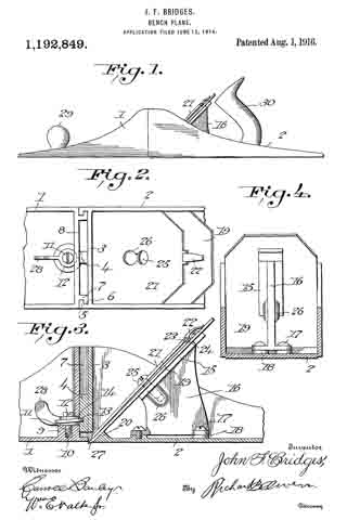
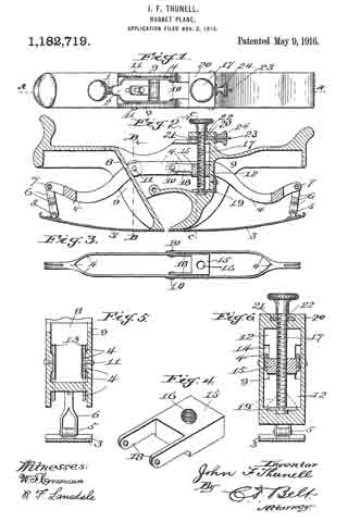
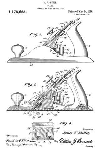
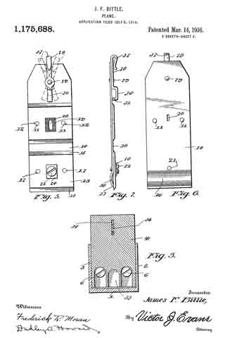
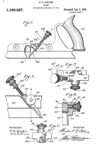
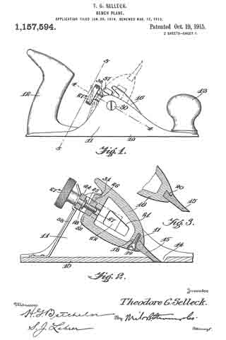
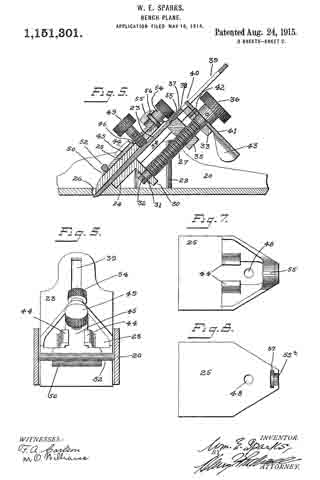
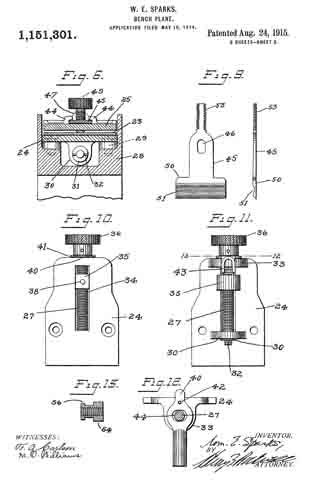
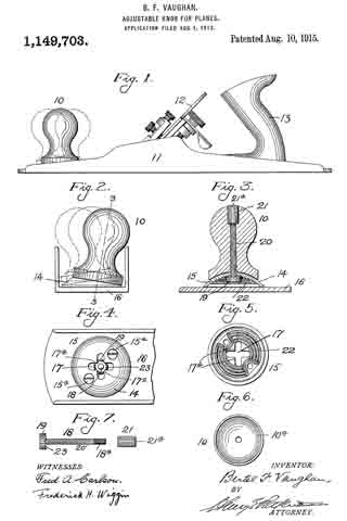
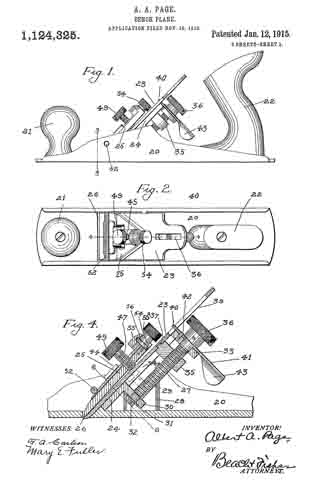
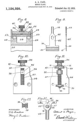
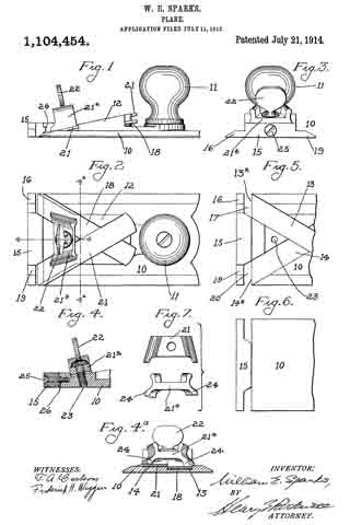
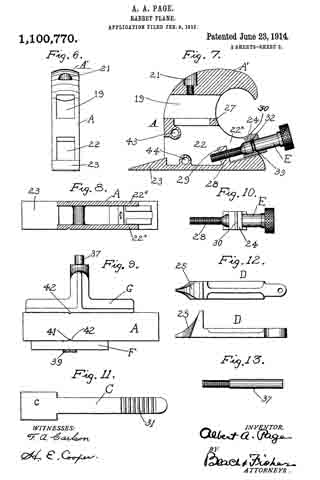
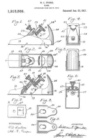
In the accompanying drawing, Figure 1 is a side elevation of a plane embodying my improvements, Fig. 2 is a top plan view of the same, Fig. 3 is a section on line 3–3 of Fig. 2, Fig. 11 is a front end elevation of the plane, Fig. 5 is a rear end elevation thereof, Fig. 6 is a section on line 6–6 of Fig. 1, Fig. 7 is a top plan view of the frog, detached, Fig. 8 is a top plan view of the clamp, and Fig. 9 is a bottom plan view of the clamp.
Referring to the drawing, the body or stock 10 is of the usual channeled form and it is preferably constructed of sheet metal. The frog 11 has the usual relation with respect to the throat 12 and said frog is constructed of a sheet metal plate 11a having downturned side portions 11b fitted within and against the side walls of the stock. In order to secure the frog firmly in place in the stock, it is necessary to employ only two fastening members such as the rivets 13, 14. These rivets pass through the extensions 11b of the frog into and through the respective side walls of the stock. It will be noted from a comparison of Figs. 1 and 3 that the rivets 13, 14 are out of line with each other whereby any turning or rotary movement of the frog relatively to the stock is absolutely prevented simply by the use of these two fastening members, one associated with each of the side walls of the stock.
At the rear of the frog the same is provided with integral downturned lugs 15, 16 provided with threaded perforations for the shank 17 of the adjusting screw 18. The cutter or bit 19 is supported on the frog 11 in the usual manner and it is of customary form except for the fact that its rear extremity is provided with a transverse slot 20 to receive the milled head 21 of the adjusting screw 18. The peripheral portion of the head 21 extends through the slot 20 for a slight distance, and as the adjusting screw is turned, the head thereof will turn freely in the slot 20 thereby advancing or retracting the cutter 19 according to the direction in which the screw is rotated. ln other words, the slot 20 in fitting over the head 21 interlocks the cutter and the adjusting screw against relative longitudinal displacement while permitting the rotation of the screw relatively to the cutter.
The frog 11 carries a pivot or stud 22, and the cutter is provided with the usual slot to fit over this stud 22. The clamp 23 consists of a sheet metal plate having downturned edges 24 and a keyhole slot 25 adapted to cooperate with the stud 22 in the usual manner. At the rear extremity of the clamp 23, the same is provided with a threaded socket 26 through which a clamping screw 27 passes into engagement with the upper surface of the cutter or bit. The cooperation between the clamping screw 27, the clamp 23, the stud 22, and the bit 19 is more or less usual and need not be further described.
In order to afford a convenient and handy grip for the workman, the stock is provided at the rear end with a palm rest 28. This consists of an upwardly directed sheet metal plate having a convex rear surface and forwardly extending lugs 29 fitting between and against the side walls of the stock. The palm rest is substantially U-shaped in cross-section, the upper edge 28a being rounded and the lower edge 28b straight and horizontal and fitting snugly against the top surface of the bed of the stock. The lugs or extensions 29 are secured to the side walls of the stock by rivets 30, 31 or similar fastening members. The rivets 30, 31 are offset from each other as in the case of the rivets 13, 14 so that turning movement of the palm rest relatively to the stock is absolutely prevented without the employment of additional fastening means, Preferably, the forwardly and upwardly curved plate 28 forming the palm rest is located at the rear extremity of the plane body or stock, and is spaced from the frog and cutter located at the intermediate part of the stock so that the adjusting screw may be located between the palm rest and cutter. The rear surface of the palm rest curves forwardly in order to fit the palm of the operator, and the form of the palm rest is such that it merges from a shallow U-shaped cross-section near the top into a deeper U-shaped cross section at the bottom where the forwardly directed extensions 29 are provided.
I do not claim herein the combination with a stock having upright side walls, of a frog comprising a sheet metal plate having integral downturned side members secured to the side walls of the stock, and integral downtnrned lugs for the bit adjusting screw, one of said lugs being struck out from the rear edge of the frog, and the other being struck out of an opening at the intermediate portion of the frog, as claimed in my co-pending application, Serial No. 778,083.
Without limiting myself to the construction shown, I claim:
1. In a plane, the combination of a stock having side walls presenting a channeled cross-section, a member fitting within the stock and having side walls abutting the respective first-named walls, and means of connection between each side wall of said member and the adjacent side wall of the stock, said two means of connection being located ont of line with each other; substantially as described.
2. In a plane, the combination of a stock having parallel side walls, a sheet metal member having bent-up extensions at the sides fitting within and against said side walls, and a rivet securing each of said extensions to the corresponding side wall of the stock, said rivets being out of line with each other; substantially as described.
3. In a plane, the combination of a stock having upright side walls, a palm rest composed of a plate resting at its lower edge on the bed of the stock and having forwardly directed extensions or lugs at the sides, and a rivet securing each extension or lug to the respective side walls of the stock, said rivets being out of line with each other; substantially as described.
In witness whereof, I have hereunto set my hand on the 5th day of July, 1913.
WILLIAM E. SPARKS.
Witnesses:
JOHN H. SHAW,
BERTHA RAY.
Copies of this patent may be obtained for five cents each, by addressing the “Commissioner of Patents, Washington, D. C.”
_________________