No. 181,357 – Improvement In Tonguing And Grooving Planes (Charles G. Miller) (1876)

[paiddownloads id=”59″]181357


UNITED STATES PATENT OFFICE.

_________________

CHARLES G. MILLER, OF NEW BRITAIN, CONNECTICUT, ASSIGNOR TO STANLEY RULE AND LEVEL COMPANY, OF SAME PLACE.

IMPROVEMENT IN TONGUING AND GROOVING PLANES.

_________________

Specification forming part of Letters Patent No. 181,357, dated August 22, 1876; application filed July 17, 1876.

_________________

To all whom it may concern:

Be it known that I, CHARLES G. MILLER, of New Britain, in the county of Hartford and State of Connecticut, have invented an Improvement in Tonguing and Grooving Planes, of which the following is a specfication:

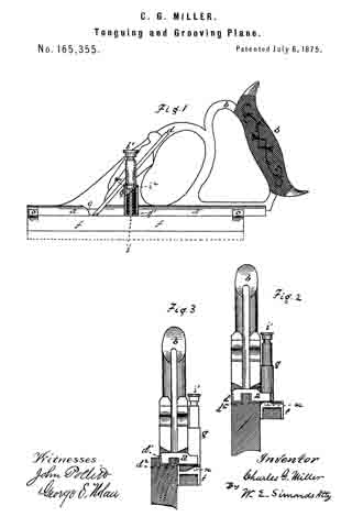
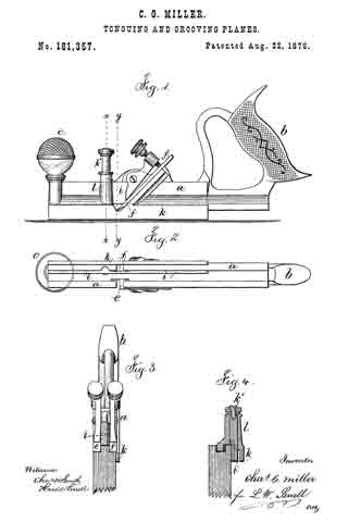
In Letters Patent No. 165,355, granted July 6, 1875, a plane is shown with two cutters and an intermediate groove for the tongue that is left upon the edge of the piece of wood, and there is a guide that can be turned around or reversed when the plane is to be used for grooving. In this plane there is but one guide for the face of the board, the guide having two sides, one of which comes against the board in planing the tongue, and the other comes against the face of the board in planing the groove after the guide has been swung around for that purpose.

My present improvement consists in the combination, with a tonguing and grooving plane and stationary guide, of a second guide that is movable in a plane parallel to the face of the stationary guide, so that the plane can be used in the ordinary manner for tonguing the edge of the board, the movable guide remaining out of the way while so doing, and upon depressing the movable guide it changes the tool into a grooving-plane, so that only one cutter is used to form the groove.

In the drawing, Figure 1 is a side view of the plane. Fig. 2 is an inverted plan. Fig. 3 is a section at x x, with the movable guide or fence out of use; and Fig. 4 is a section at the line y y, representing the plane as in use for forming a groove.

The stock a, handle b, and knob c, are of any usual or desired size or character. The two cutters e and f are also constructed in the ordinary way and clamped, preferably by levers and thumb-screws. The stationary guide or fence It is upon the plane-stock, and I runs against the face of the board in the ordinary manner when the plane is being used to form a tongue. The cutter e is of the same width as the tongue ; hence to use said cutter in forming a groove it is only necessary to introduce a movable fence or guide at the proper distance from the cutter to enable the work-man to use the plane for grooving the wood for the reception of the tongue.

I accomplish this object by using the movable fence or guide i that moves in a plane parallel with the face of the stationary guide k.

I have shown this guide i as sliding vertically in a narrow channel made through the plane-stock, and the guide i is attached at one side of a headed stud, k’, that passes through the hollow stud l upon the plane-stock.

The portion of the stock that forms the bed for the cutters is slotted or channeled to allow of the movement of this guide ; so, also, is the stud upon which the knob e is placed. When the guide fi is pushed down into position shown in Fig. 4, the plane is adapted to grooving, and when said guide is not needed, it is moved in the plane parallel to the face of the board so as to be out of the way when using the plane for forming the tongue. This guide i might be pivoted at one end and swing in the same plane of motion as aforesaid, in a manner similar to a knife-blade.

I claim as my invention —

The combination, with a tonguing-plane, having stock a, cutters e and f, and guide k, of the second guide or fence i, moving in a plane parallel to the face of the stationary guide, substantially as set forth.

Signed by me this 7th day of July, A. D.
1876.

C. G. MILLER.

Witnesses:
JULIUS H. PEASE,
ISAAC PORTER.

No. 165,355 – Improvement In Tonguing And Grooving Planes (Charles G. Miller) (1875)

[paiddownloads id=”57″]165355


UNITED STATES PATENT OFFICE.

_________________

CHARLES G. MILLER, OF NEW BRITAIN, CONNECTICUT, ASSIGNOR TO THE STANLEY RULE AND LEVEL COMPANY, OF SAME PLACE.

IMPROVEMENT IN TONGUING AND GROOVING PLANES.

_________________

Specification forming part of Letters Patent No. 165,355, dated July 6, 1875; application filed April 9, 1875.

_________________

To all whom it may concern:

Be it known that I, CHARLES G. MILLER, of New Britain, in the county of Hartford and State of Connecticut, have invented an Improvement in Tonguing and Grooving Planes, of which the following is a description and specification, reference being had to the accompanying drawings, where —

Figure 1 is a side view of a plane embodying my invention, the view showing that side of the tool upon which the shifting guide, hereinafter described, is hung. The tool is adjusted as a tonguing-plane. The view from this side is, however, precisely the same when the tool is adjusted as a grooving-plane. Fig. 2 is a front-end view of the tool adjusted as a tonguing-plane, showing the pivot, on which the shifting guide is hung, in central vertical section. Fig. 3 is a front-end view of the tool adjusted as a grooving-plane.

This invention is a device which is, at pleasure, a plane for tonguing the edges of boards, or a plane for grooving the edges cf boards to receive such tongues. It is a tool for use in making what is known to carpenters as “matched stuff,” and combines in itself both a tonguing and a grooving tool.

The invention consists in a shifting guide, which can be adjusted so as to leave both the knives or chisels uncovered, making a tonguing-plane of the tool; or it can be adjusted to cover one of the chisels or knives, making a grooving-plane.

The letter a denotes the metallic stock or body of the tool; b, the handle, and c the throat, down which runs what carpenters call the “iron” d, forked at its lower end into the two chisels d1 d2, which do the cutting. e denotes the wedge which holds the iron in place. The letter f denotes the shifting guide, eccentrically attached to the shaft i, hung and rotating in the socket g, attached to the stock a. The pin i1 runs into the top of the shaft or trunnion i, and forms, practically, a part thereof. The spring m, bearing between the shoulders g1 i2, presses the guide f constantly upward. In either adjustment, for tonguing or for grooving, the guide f is held to position by the pins n, (shown in dotted lines,) which project downward from the fingers o, which project side-wise from the stock a, three teats entering corresponding holes in the top of the guide f.

When the operator desires to shift the adjustment of the guide f, he presses downward upon the top of the pin i1 till the guide clears the pins n, when it can be readily rotated upon its pivot in the socket g from one adjustment to the other.

In place of the vertical movement allowed, by this construction and arrangement, to the guide f, I contemplate depriving the guide of this vertical play, and in place thereof make one of the pins n, or both of them, a spring-catch.

When the guide f is adjusted as shown in Fig. 2, both the chisels d1 d2 are left uncovered for work, and the tool forms a tonguing-plane. When the guide f is adjusted as shown in Fig. 3, one of the chisels is covered, and the tool forms a grooving-plane; and these differences of adjustment are due to the fact that the guide f is hung eccentrically upon its pivot.

I claim as my invention —

ln combination with the body or stock a and the chisels d1 d2, the guide f, having adjustments to cover and uncover one of the chisels, substantially as shown and described.

CHARLES G. MILLER.

Witnesses:
FRED. N. STANLEY,
T. A. CONKLIN.

No. 142,037 – Improvement In Match Planes (Charles G. Miller) (1873)

[paiddownloads id=”1″]13957


UNITED STATES PATENT OFFICE.

_________________

CHARLES G. MILLER, OF NEW BRITAIN, CONNECTICUT, ASSIGNOR TO OLIVER S. JUDD AND CHARLES BLAKESLEE, OF SAME PLACE.

IMPROVEMENT IN MATCH-PLANES.

_________________

Specification forming part of Letters Patent No. 13,957, dated December 18, 1855.

_________________

To all whom it may concern:

Be it known that I, CHARLES G. MILLER, of New Britain, in the county of Hartford and State of Connecticut, have invented a Combined Tonguing and Grooving Plane, of which the following is a specification, reference being had to the accompanying drawings, in which —

Figure 1 is a side view of the implement. Fig. 2 is an end view of the forward end of the same — the end A. Fig. 3 is a flat view of the under side of the iron.

The plane or tool to which this invention appertains is made of cast metal ; and the invention consists in making an arch to span the cross-cut in which the plane-iron lies, so as to support both ends of the tool, which arch, at the same time, forms a part of the handle of the plane, and forms a back or buttress for the adjusting-screw which controls the adjustment of the plane-iron, this arch being so set on the tool that it can be cast with it all in one piece.

The tool, as shown in the drawings, is made of cast metal, though it may be, with obvious modifications, made of wood or other suitable material. The letter a, indicates the body of the tool, and b the handle, which is hollow, being cored out in casting, from the lower end. That part of the tool to the left of the dotted line x in Fig. 2 does the grooving, and the part to the right of this dotted line does the tonguing, the two parts being so united that either part can be used separately without interfering with the other part. The letter c indicates the chisel or “iron,” so called, which does the cutting. It has three cutting-prongs, c1, c2, and c3. The cutting-prong c1 is the grooving-iron, and c2 and c3 are the tonguing-irons. The whole iron lies upon the oblique ledge or bed a1, and is secured thereto by the headed screws d d1l, running through the cap-plate e, and through the slots d2 d3 into the bed a1. The slots d2 d3 allow the iron to he set and adjusted. An arch, a2, springing from the body of the tool, goes over the top of the iron. Into the under side of this arch is fixed the small screw-bar f upon which is the thumb-nut f1, having a projection, f2, upon one side, bearing upon the top or upper end of the iron c. By means of this thumb-nut the iron can be nicely adjusted downward, when the screws d d1 are slightly loosened. It is screwed down upon the upper end of the iron when it has been adjusted, and thus acts as a support to keep the iron from slipping back: when the tool is hard pressed upon. The letter g indicates the handle for the left hand of the operator.

The adjusting and supporting thumb-nut is applicable to all plane-irons.

From the foregoing description, it will be seen that the arch a2 spans the cross-cut or opening in which the plane-iron lies; that this cross-cut or opening must be open on one side of the tool, to admit of the whole being cast in one piece; that, since this cross-cut is thus open on one side of the arch, it is necessary to support the two ends of the body of the tool; that this arch also forms a part of the handle of the tool; that it forms a buttress for the adjusting screw or nut f1, and that it is so set on the body af as to admit of the whole being cast in one piece.

I claim as my invention —

The combination of the body a, having the cross-cut for the iron open at one side, and the arch a2, spanning the cross-cut and forming a buttress for the adjusting-screw, and also a part of the handle, all of cast metal, in one piece, substantially as described, and for the purposes set forth.

CHARLES G. MILLER.

Witnesses:
F. M. JEROME,
E. KEMPSHALL.

No. 131,367 – Improvement In Carpenters Plows (Charles G. Miller) (1872)

[paiddownloads id=”55″]131367


UNITED STATES PATENT OFFICE.

_________________

CHARLES G. MILLER, OF NEW BRITAIN, CONNECTICUT.

IMPROVEMENT IN CARPENTERS’ PLOWS

_________________

Specification forming part of Letters Patent No. 131,367, dated September 17, 1872.

_________________

To all whom it may concern:

Be it known that I, CHARLES G. MILLER, of New Britain, in the county of Hartford and State of Connecticut, have invented certain new and useful Improvements in Carpenters’ Plows, of which the following is a specification, reference being had to the accompanying drawing, in which —

Figure 1 is a side elevation of that side in which the cutting-“iron” is held. Fig. 2 is a side elevation from the opposite side. Fig. 3 is a plan view. Fig. 4 is a view of the under side of the cutting-“iron” Fig. 5 is a central vertical section ofthe handle through the dotted line x x.

The letter a indicates the main body of the plow, cast of metal, in one piece, with ornamental designs thereupon ; b, the guide at the left side of the plow, also cast in one piece. The letters c c’ indicate rods, which are screwed into the side of the main body a, and thereby made detachable therefrom at pleasure, so that the plow can be taken apart and packed into a small compass when not in use. This is believed to be a new feature and an improvement. The guide b slides upon these rods, being set at any desired point by means of the set-screws b1 b2, which are placed underneath the rods, and thus out of the way of the left hand of the operator. The placing of these screws in this position is also believed to be new. A knob, b3, pierced for the introduction of the rod c, projects from the left side of the guide b, thus affording a support for the left hand of the operator. This also is believed to be new. The cutting-chisel d, commonly called the “iron,” is secured in its place when in use by means of the balanced clamp e, embracing the body a, pivoted at e’, and operated by means of the cam f, which has an adjusting-screw, f1, by means of which the clamp can be made to pinch the “iron” with as much or as little force as desired. The application of such a clamp to this purpose and in this manner is believed to be new. To the end of this clamp is attached a shaving-guide, f2, not greatly unlike, in shape, the mold-board of a farmer’s plow, which avails to turn the shavings to the right and away from the plow as the chisel produces them from the wood. This combination of a shaving-guide with the clamp is believed to be new. The “iron” d is roughened on the under surface, at its base end, for the purpose of taking hold upon the seat h, upon which it rests. The iron also has a lengthwise groove, d’, which fits upon the edge a1, and thus keeps the iron from any sidewise motion. The base end of the iron rests upon the seat h, but it does not touch the edge a1 till it comes down where the star is, thus allowing the clamp to spring it firnily down into place, and insuring that the cutting-point of the “iron” shall set firmly upon the edge a1 at its lower end, thus obviating any clatter of the “iron.” This arrangenient and construction is believed to be new. Near the front end of the main body at is a gage to determine the depth of the cut of the “iron,” consisting of the fiat metal foot i, attached to the round pillar i1, set at any desired point by the set-screw i2.

The handle s is fastened to the main body a in a peculiar manner. This handle is of wood, slotted on its under side down to the line s’, the width of the slot being just the thickness of the rib a2, which rib is pierced with holes a3. Before the handle is put on, these holes a3 are filled with saw-dust and glue mixed, or with pieces of wood having glue upon them,and when the handle is put on the glue sets and thus fastens the handle on. This is also believed to be new.

I claim as my invention —

1. The combination of the cast-metal body a, the cast-metal guide b, and the rods c c’
screwed into the body a so as to be detachable, for the purpose set forth.

2. The combination of the cast-metal body a, the rods c c’, and the guide b having the set-screws for the said rods under the rods, substantially as described, and for the purpose set forth.

3. The combination of the main body a, rod c, guide b, and knob b3 attached to the guide and pierced for the entrance of the rod, substantially as described, and for the purpose set forth.

4. The balanced clamp e pivoted to the main body a, and operated by means of the cam f, substantially as described, and for the purpose set forth.

5. In combination with the balanced clamp e, the shaving-guide f2 attached thereto, substantially as described.

6. The combination of the chisel or iron, roughened and grooved as described, with the main body as, having an edge, a1, so formed that the “iron” will only touch the body at two points, viz., the seat h and the lower part of the edge a1, substantially as described, and for the purpose set forth.

7. The construction and method shown for attaching the handle s to the main body.

CHARLES G. MILLER.

Witnesses:
WM. E. SIMONDS,
GEORGE G. SILL.