No. 619,394 – Bench-Plane (Maschil D. Converse) (1899)

[paiddownloads id=”538″]619394


UNITED STATES PATENT OFFICE.

_________________

MASCHIL D. CONVERSE, OF NEW YORK, N. Y.,
ASSIGNOR TO JOHN J. TOWER, OF SAME PLACE.

BENCH-PLANE.

_________________

SPECIFICATION forming part of Letters Patent No. 619,394, dated February 14, 1899.
Application filed June 20, 1898. Serial No. 683,931. (No model.)

_________________

To all whom it may concern:

Be it known that I, MASCHIL D. CONVERSE, a citizen of the United States, residing in the city, county, and State of New York, have invented certain new and useful Improvements in Bench-Planes, of which the following is a specification.

My present invention relates more especially to that type of bench-planes commonly made with iron stocks, and particularly to sidewise-adjustment mechanisms for the same.

Planes have been provided with mechanisms for lateral adjustment that in many cases are so constructed, disposed, and applied as to involve piercing of the bits with holes or slots or cutting of grooves longitudinally in one or the other of the flat sides thereof, requiring in consequence that the bits be made thicker and heavier than is desirable to compensate for the lack of stiffness that would result from such form in the bit and otherwise, and in other cases the construction and manner of disposing and applying such mechanisms are such that they encroach upon the radial hand-space about the handle of the plane, more especially on the front side thereof, seriously interfering with and sometimes to the injury of the hand of the operator, and by such near proximity, especially of the free ends of the operating-levers, the bits are constantly liable to be and are thereby frequently accidentally disturbed and put out of lateral adjustment.

The objects of my invention are to overcome these defects, to simplify construction, reduce the cost of manufacture, and improve the efficiency of such tools.

My invention consists in placing the fulcrum-point of a mechanism for lateral adjustment of the plane-bit at the bearing end of a cramp-screw in the outer end of the upper bit-clamp plate or in axial coincidence therewith and in so constructing and disposing all parts of said mechanism that the objects above stated will be attained, all of which will hereinafter be fully described and claimed.

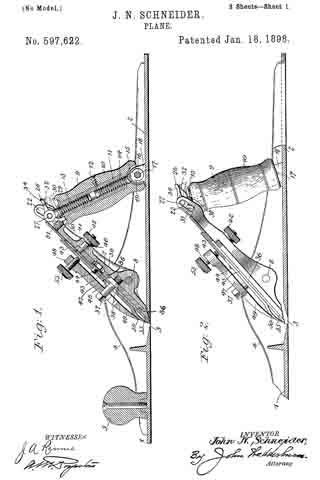
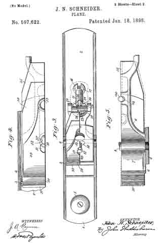
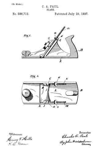
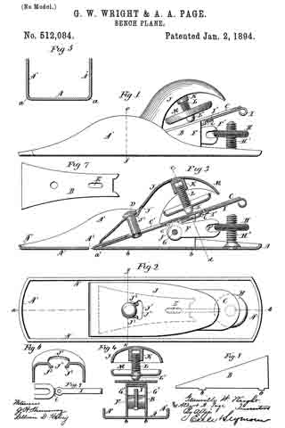
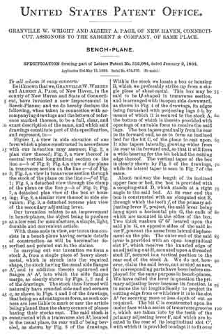
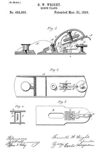
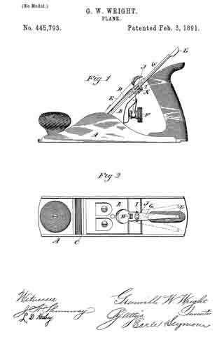
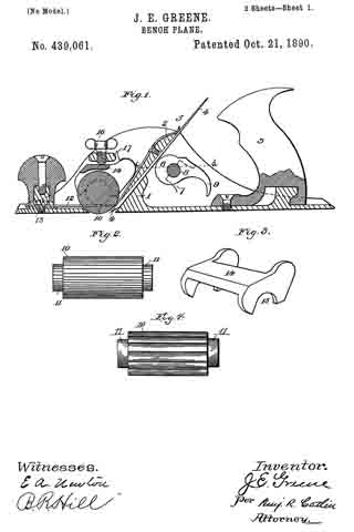
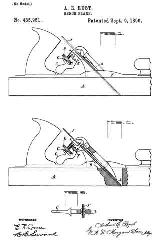
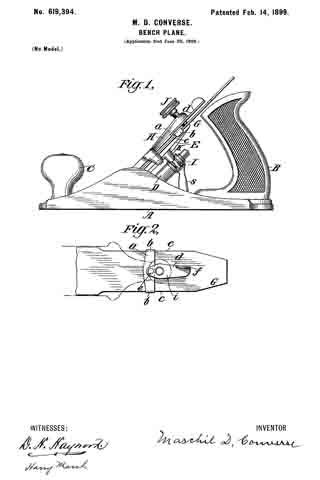
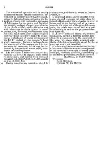
In the drawings, Figure 1 is a side elevation of a bench-plane of the class referred to, showing the construction, application, and disposition of the members in part of my invention. Fig. 2 is a plan view of parts of Fig. 1, showing further the construction, application, and operation of my invention. These figures will presently be more fully described in detail.

Like letters indicate corresponding parts in each figure.

A is a stock, block, or body of a bench-plane of common pattern, having the usual handle B, knob C, and a post D, centrally upon which is mounted a longitudinally-movable inclined plate E, forming a bed for the bit G, above which is another plate H, also longitudinally movable, with a cramp-screw J passing through its outer extremity from the top side, which, together with the said named plates E and H, comprises a screw-cramped clamp for securing the bit G after its adjustment laterally and longitudinally is effected.

I is a worm-screw (provided with a lever s) fastened pivotally to the post D to engage a rack K on the nether bit-clamp plate or bed E, making a known device for adjustment of the bit longitudinally.

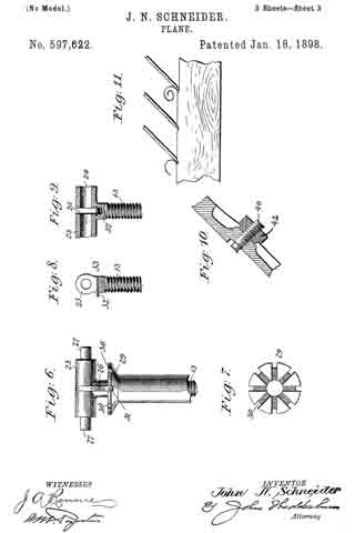
a is a metal strap or casting, preferably arranged on the upper side, with ends b b turned right angularly to embrace the outer parallel edges c c of the bit G.

d is a lever operatively pivoted to the center of the strap at e, said lever being fulcrumed on the bearing end of the cramp-screw J in the outer end of the plate H and preferably arranged in a plane above the lateral plane of the bit G. The free end f of this lever d, which is also preferably disposed along the upper side of the bit, is suitably elongated and formed up to insure ease and accuracy of movement in manipulation.

The clamp-plates E and H are so attached to each other and to the post D, which is integral with the stock A, that while each has longitudinal freedom they have substantially no edgewise play. Therefore the fulcrum of the lever d, being on the bearing end of the cramp-screw J at the outer end of the upper bit-clamp plate H, is substantially fixed against lateral movement relatively the plane-stock A. The bit G, on the contrary, is fitted so as to have considerable edgewise freedom at its outer end, while the cutting end is confined against lateral movement, the purposes of which are apparent.

The mechanical operation will be readily understood without further explanation; but it should be specially noted that by a mechanism for lateral adjustment having the disposition of parts with the location and means of fulcrumage herein shown and described the necessity and cost of grooving or piercing of the bits is avoided, so that the same may with advantage be made lighter in consequence, and, moreover, encroachment upon the radial hand-space about the plane-handle is obviated and liability to injury to or accidental disturbance of lateral adjustment of the bit by contact of the operator’s hand wholly overcome. I fulcrum the lever d upon the bearing end of the cramp-screw J for convenience and economy; but it may be fulcrumed by independent means axially coincident to the cramp-screw.

I do not claim a transverse strap or bar, broadly, in a device to engage a plane-bit for its adjustment, such having been used and described in Letters Patent No. 64,790 as early as May 14, 1867; but,

Having described my invention, what I do claim as new, and desire to secure by Letters Patent, is —

1. In a bench-plane, a lever-actuated mechanism adapted to engage the outer edges for lateral adjustment of the bit, having its lever fulcrumed to the bearing end of a cramp-screw in the outer end of the upper bit-clamp plate, the whole constructed and arranged substantially as and for the purposes shown and described.

2. A lever-actuated lateral-adjustment mechanism, having a fulcrum axially coincident to a cramp-screw in the outer end of the upper bit-clamp plate, arranged, relatively of the bit, substantially as and for the purposes shown and described.

3. A lateral-adjustment mechanism, having a fulcrum axially coincident to a cramp-screw in the outer end of an upper bit-clamp plate, arranged, relatively of the bit, substantially as and for the purposes shown and described.

MASCHIL D. CONVERSE.

Witnesses:
PAUL GORHAM,
DWIGHT W. DE MOTTE.

No. 597,622 – Plane (John N. Schneider) (1898)

[paiddownloads id=”534″]597622


UNITED STATES PATENT OFFICE.

_________________

JOHN N. SCHNEIDER, OF MENDOTA, ILLINOIS.

PLANE.

_________________

SPECIFICATION forming part of Letters Patent No. 597,622, dated January 18, 1898.
Application filed January 14, 1897. Serial No. 619,148. (No model.)

_________________

To all whom it may concern:

Be it known that I, JOHN N. SCHNEIDER, a citizen of the United States, residing at Mendota, in the county of La Salle and State of Illinois, have invented certain new and useful Improvements in Planes; and I do hereby declare the following to be a full, clear, and exact description of the invention, such as will enable others skilled in the art to which it appertains to make and use the same.

My invention relates to improvements in hand-planes, and has for its object the production of an improved plane the bit of which will be autornatically retired from its operative position during the back stroke of the plane.

A further object is the production of novel mechanism for the adjustment of the bit which may be regulated while the plane is being moved over the surface to be planed and without removing the hand from the handle.

Subordinate to these general objects a still further object of my invention is to provide certain novel and efficient mechanism for accomplishing the various attachments of the several parts of the device, as will hereinafter be made apparent.

To the accomplishment of the objects stated my invention consists in providing a plane-stock with a pivoted bit-stock and with a handle designed by its rotation to regulate the adjustment of the bit-stock and to automatically throw the bit into its operative or inoperative positions as the pressure exerted upon the handle is directed to propel or retract the plane.

In order that the utility of the invention may be readily understood, it may be remarked that in the usual manipulation of devices of this general character the backward movement or stroke of the plane is accompanied by the abrasion of the bit, which gradually turns the cutting edge and necessitates an additional pressure upon the plane in order to secure a proper bite upon the material to be planed. It is necessary in order to avoid this abrasion and the consequent wear and distortion of the cutting instrument to raise the plane entirely from the surface of the material during its back stroke, which is not only inconvenient, but where a large plane — as, for instance, a jack-plane — is employed it is absolutely impossible, and the consequence is that the plane is dragged back, the grit upon the material serving to grind the rear face of the cutting edge and finally forrning a shoulder thereon, which must be actually forced into the surface of the wood in order to secure a bite sufficient to remove a shaving. It has also been necessary heretofore to discontinue the operation of planing when it has been desired to adjust the bite of the cutting-bit, and, as I have stated, the object of the present invention is to overcome the wear upon the cutting edge and the necessity for discontinuing the rnanipulation of the plane when it is desired to accomplish the adjustment of the bit.

In the accompanying drawings, forming a part of this specification, Figure 1 is a central vertical section through my device, showing the bit in an operative position. Fig. 2 is a side elevation, partly in section, of a portion of a plane, showing the bit retired or in inoperative position. Fig. 3 is a top plan view with certain of the parts broken away. Fig.
4 is a top plan view of a portion of the bit-stock and the mechanism supported thereby. Fig. 5 is a bottom plan view of the subject matter of Fig. 4, showing the lateral adjustment of the bit in dotted lines and illustrating a modified form of the fulcrum-pin. Fig. 6 is a detail view of a portion of the adjustment-sleeve index and locking-plate and the upper section of a bit-stock-adjusting bolt. Fig. 7 is a plan view of my indicator and locking-plate. Figs. 8 and 9 are detail views of the upper extremity of the bit-adjusting bolt. Fig. 10 is a view of a modified form of the mechanism comprehended by the parts 40 and 42. Fig. 11 is a diagrammatic view illustrative of the edect of the ordinary manipulation of the plane upon the cutting edge of its bit.

Referring to the numerals on the drawings, 1 indicates a plane-stock consisting, as usual, of a sole-plate 2, provided with a transverse bit-aperture 3 and with frame or side pieces 4, preferably of the configuration illustrated.

5 indicates the front guiding knob or handle, secured upon the sole-plate in the usual manner, and 6 indicates a bit-stock consisting of a bed-plate 7, provided with a bit-iron and its retaining and lateral adjusting mechanism and fulcrumed between the side pieces 4 by a fulcrum-pin 3, secured at its opposite ends to the side pieces 4 and located a suitable distance to the rear of the bit-aperture 3 and preferably near the lower extremity of the bed-plate.

9 indicates the handle of my device, consisting, preferably, of the handle-casing 10, having an internal adjustment-sleeve 11. secured thereto, as by a screw 12, and internally screw-threaded in opposite directions adjacent to its opposite extremities for the reception of the separated and oppositely screw-threaded upper and lower sections 13 and 14; of the adjustment-bolt 15, the lower extremity 16 of which is pivoted upon the handle-pintle or fulcrum-pin 17, carried by a pair of upwardly-extending lugs 13, carried by the sole-plate. The lower end of the handle-casing is preferably recessed, as at 19, for the reception of the lugs 13, in order to accommodate longitudinal adjustment of the former. The rear extremity of the bit-stock is preferably bifurcated, and the bifurcated extremities are provided with slots 22, arranged tangentially with respect to an are described by the upper extremity of the adjustment-bolt 15 when the latter is swung upon the fulcrum-pin 17. The upper extremity of said adjustment-bolt is provided with a bearing-thimble 23, disposed at right angles to the bolt and provided with a bore 24: and with a transverse slot 25, designed for the reception of the locking-lever 26, carried by a pin 27, passed through the bore 24 in the thimble 23 and designed to be engaged by the slots 22 in the bifurcated extremities 20 and 21 of the bit-stock bed-plate.

29 indicates what I will term a “locking and indicating plate” secured upon or made integral with the upper extremity of the adjustment-sleeve 11 and provided with a series of radial notches 30, designed to receive the locking end 31 of the locking-lever 26, which latter is spring-actuated, as by a bent spring 32, passing through a spring-aperture 33 in the adjustment-bolt, and bearing at one extremity against the handle 34 of the locking-lever.

It will now be observed that the bit-iron 35, carried by the bit-stock, will be projected through the bit-aperture 3 in the sole-plate or will be retracted to a position above the lower surface of the sole-plate by the oscillation of the bit-stock upon the fulcrum-pin 3, and it is for the purpose of accomplishing this movement of the bit for the purpose of throwing it into the operative position or of retiring it to the inoperative position as the plane is moved forward or rearward that I have employed a pivoted or oscillating handle having loose connection with the upper extremity of the bit-stock.

When the plane is propelled, as in use, pressure is exerted upon the handle 9 in the direction of the movement of the plane, causing the extremities of the pin 27, carried at the end of the adjustment-bolt 15, to move to the bottom of the slots 22, swinging the bit-stock upon its pivot and throwing the cutting edge of the bit 35 into its operative position below the sole-plate 2. The shaving is now removed from the surface of material to be planed and extends through the aperture 3 in the usual manner. The end of the stroke having been reached, pressure is now exerted by the operator upon the handle 9 in the opposite direction, causing it to be oscillated rearwardly or in the direction of the retraction of the plane, and the pin 27 will seek the opposite ends of the slots 22, which by reason of the relation of said slots and the direction of movement of the pin will cause the bit-stock to be again oscillated upon its fulcrum-pin 8, raising the cutting edge of the bit 35 to the inoperative position, as indicated in Fig. 2 of the drawings. The shaving which would otherwise accumulate in the aperture 3 is by this operation ejected from immediate proximity to the aperture by the movement of the bit.

Supposing now it is desired to adjust the bite of the plane iron or bit, by which I mean the distance it will project below the sole-plate in the operative position, the thumb of the operator is placed upon the handle 34: of the locking-lever, depressing it and causing the locking end 31 of the lever to be disengaged from the locking-plate 29. The handle 9 is now rotated in one direction or the other, as it is desired, to lengthen or contract the adjusting-bolt 15, it being observed that by reason of the oppositely screw-threaded connections of the sections of the adjustment-bolt and adjustment-sleeve the bolt-sections will be drawn together or separated by the rotation of the handle and thus caused to adjust the angle of inclination of the bit-stock, which, as will be apparent, will regulate the bite of the plane-bit. As soon as the desired adjustment has been accomplished the handle 34 of the locking-lever is released and the spring 32 will elevate the handle and will bring the locking end of the lever into engagement with the adjacent notch in the locking-plate 29. By this means the adjustment of the bit-stock and its iron is fixed.

It is obvious that the adjustment just described can be effected without interrupting the operation of planing and without in any manner affecting the operation of the device for the purpose of throwing the bit into or out of its operative position. For the purpose of determining the extent of the adjustment I prefer to number the notches upon the looking and indicator plate 29, as indicated in Fig. 7 of the drawings, it being apparent that the degree of rotation of the handle, as indicated by the progression of the notches, will determine the extent of the adjustment effected through the mechanism described, and which I will term “bit-adjusting” mechanism. When it is desired to throw the locking-lever out of operation — as, for instance, when nicety of adjustment is not required — the spring 32 may be passed through the aperture 33 to the position indicated in dotted lines of Fig. 1 of the drawings, in which position it will hold the locking end of the locking-lever out of operation, and the handle may then be turned in either direction at will.

Having now described the bit-actuating mechanism and the bit-adjusting mechanism, I shall now proceed to a description of the novel mechanism by means of which the bit or iron is adjustably secured upon the bed-plate of the bit-stock.

36 indicates a bit-supporting plate pivotally secured to the face of a depressed portion of the bit-stock by means of a bit fulcrum-bolt 37, screwed into the bed-plate 7 at a point adjacent to the fulcrum-pin 8 and provided with a conoidal portion 38, designed to be received by a correlatively-shaped aperture 39 in a bit-supporting plate 36.

40 indicates the bit-adjustment bolt, secured at one extremity to the plate 36 near its end and projecting through a curved aperture 41, designed to accommodate its movement in the bed-plate 7, incurred in a degree corresponding to the arc of movement of the adjustment-bolt.

42 indicates a thumb-nut screwed upon the extremity of the bolt 40 and designed by its abutment against the lower surface of the bed-plate to secure the bolt in its adjusted positions in the manner hereinafter made apparent. The iron or bit 35 is now placed upon the surface of the stock and the plate 36 and is secured to the superimposed cap-iron 43 by the screw-bolt 44, the head of which its closely within an aperture in the plate 36 to prevent lateral movement of the bit and cap iron upon said plate, an elongated recess being provided in the surface of the stock to permit the movement of the head ot the bolt 44, when the plate 36 is swung upon the pivot for the purpose of alining the cutting edge of the bit with the surface of the sole-plate 2. The bit-iron is provided with an elongated slot 45, designed to accommodate the bolt 37 when the bit is moved longitudinally, and the cap-iron 43 is provided with an aperture 46, through which said bolt is passed, as illustrated.

47 indicates a compression-lever provided with a pointed extremity 49, designed to bear against the spring end 50 of the cap-iron, which bears against the bit adjacent to its cutting edge. The compression-lever is preferably provided with an aperture 51, correlative in size and shape with the hexagonal head of the bolt 37 and designed to permit the same to be passed therethrough, and with a preferably small recess 52, extending from the aperture 51, into which recess the bolt proper is slipped, as indicated in Figs. 1 and 4 of the drawings.

53 indicates a compression-bolt screwed to the rear end of the compression-lever and designed to abut against the cap-iron. It will thus be seen that the bit is clamped firmly against a suitable bit-supporting plate 36 and may be swung upon the bolt 37, as indicated in dotted lines in Fig. 5, for the purpose of alining the cutting edge of the bit with the surface of the sole-plate 2.

Summarizing briefly, I have by the construction and arrangement described and illustrated produced a plane provided with means for the lateral and longitudinal adjustment of the bit upon the bit-stock, mechanism for adjusting the bit-stock through the movement of the handle, and mechanism for actuating the bit-stock to throw the bit into or out of operative position automatically as the plane is propelled or retracted, as in use.

I do not desire to limit myself to the details of construction herein shown and described, but reserve to myself the right to change, modify, or vary such details within the scope of my invention.

Having thus described my invention, what I claim as new, and desire to secure by Letters Patent, is —

1. The combination with a plane-stock, bit and oscillatory bit-stock, of a rotary and oscillatory handle operatively connected with the bit-stock, means whereby its oscillation will actuate the bit-stock, and whereby its rotation will adjust its connection therewith, substantially as specified.

2. The combination with a plane-stock, bit and oscillatory bit-stock, of a rotatable plane-handle operatively connected with the bit-stock and means for causing its rotation to adjust its connection with said bit-stock, substantially as specified.

3. The combination with a plane-stock, bit and oscillatory bit-stock, of an oscillatory handle and a slot-and-pin connection between the upper extremity of the handle and bit-stock, substantially as specified.

4. The combination with a plane-stock, bit and oscillatory bit-stock, of an oscillatory handle, bit-adjusting mechanism actuated by the movement of the handle and means carried by the handle for locking said bit-adjusting mechanism, substantially as specified.

5. The combination with a plane, a bit and oscillatory bit-stock, of a rotary handle operatively connected with the bit-stock and designed by its rotation to adjust the same, of an index and locking plate operatively connected with the handle, and a locking-lever operatively connected with said plate, substantially as specified.

6. The combination with a plane-stock, of an oscillatory bit-stock, an oscillatory handle, bit-stock-adjusting mechanism intermediate the handle and bit-stock, a bit adjustable upon the bit-stock, and locking mechanism intermediate of the handle and bit-stock, substantially as specified.

7. The combination with a plane-stock, bit and oscillatory bit-stock, of an oscillatory handle and a sectional adjustment-bolt operatively connected with the handle and with the bit-stock, substantially as specified.

8. The combination with a plane-stock, bit and oscillatory bit-stock, of a sectional adjustment-bolt pivoted upon the plane-stock and operatively connected with the bit-stock, a handle operatively connected with the adjustment-bolt and cooperating locking mechanism carried by the bolt and handle, substantially as specified.

9. The combination with a plane-stock, bit and oscillatory bit-stock, of a sectional oscillatory adjustment-bolt connected with the bit-stock by a slot-and-pin connection, a handle operatively connected with a sectional adjustment-bolt, an indicator and locking-plate carried by the handle and a locking-lever carried by the bolt, substantially as specified.

10. The combination with a plane-stock, bit and oscillatory bit-stock, of a sectional adjustment-bolt operatively connected with the bit-stock, a handle operatively connected with the bolt, a notched indicator and locking-plate carried by the handle, a locking-lever carried by the bolt and a spring designed to be adjusted for the purpose of causing it to actuate the locking-lever or to prevent such actuation, substantially as specified.

In testimony whereof I have signed this specification in the presence of two subscribing witnesses.

JOHN N. SCHNEIDER.

Witnesses:
JOHN W. KNAUER,
EMIL J. HESS.

No. 586,712 – Plane (Charles A. Paul) (1897)

[paiddownloads id=”531″]586712


UNITED STATES PATENT OFFICE.

_________________

CHARLES A. PAUL, OF ORLANDO, OKLAHOMA TERRITORY.

PLANE.

_________________

SPECIFICATION forming part of Letters Patent No. 586,712, dated July 20, 1897.
Application filed May 11, 1897. Serial No. 591,136. (No model.)

_________________

To all whom it may concern:

Be it known that I, CHARLES A. PAUL, a citizen of the United States, residing at Orlando, in the county of Logan and Territory of Oklahoma, have invented certain new and useful Improvements in Planes; and l do hereby declare the following to be a full, clear, and exact description of the invention, such as will enable others skilled in the art to which it appertains to make and use the same.

This invention relates to planes, and more particularly to plane-bits.

My object is to provide an improved and simple plane-bit which will be capable of quick and easy adjustment or removal.

The invention consists of certain novel features and combinations appearing more in detail hereinafter.

In the accompanying drawings, Figure 1 is a sectional side elevation, and Fig. 2 a top view.

A designates the plane-body, which is provided with the usual handle B.

The sides of the body are provided with respective rearwardly-inclined bit-slides C, which have arc-shaped notches E in their upper ends. I also proyide the sides with inwardly-projecting lugs G and H, through which pass respective clamping-screws I and J.

My improved bit K is provided with integral upwardly-projecting screws L and M, on which are located circular adjusting-nuts N and O, which project into the notches E and F.

The bit is adjusted in the following manner: The nuts are turned to advance or retreat the bit, and when properly adjusted the clamping screws are screwed down, thus holding the bit firmly in adjusted position. The bit is not quite the width of the plane-body, so that either nut can be adjusted to slightly tilt it either to the right or left, so that the cutting edge will lie parallel with the bottom of the plane.

Having thus described the invention, what is claimed as new is —

1. In a plane, the combination with a plane-body of inclined bit-slides securely fastened thereto, a bit having screw-threaded arms, located at opposite sides thereof and secured thereto and nuts carried on said arms and engaging with the bit-slides whereby either or both sides of the bit can be adjusted.

2. In a plane, the combination with a plane-body, of inclined bit-slides secured thereto, said slides being provided with notches, a bit movable on the slides and having screw-threaded arms secured thereto and located at opposite sides thereof, and circular nuts carried on the arms and loosely received in the notches.

3. In a plane, the combination with a plane-body, of inclined bit-slides securely fastened thereto, said slides being provided with notches, a bit movable on the slides and having screw-threaded arms at its opposite sides, nuts carried on the arms and loosely received in the notches, ears secured to the plane-body, and clamping-screws passing through the ears and binding on the bit-slides.

4. In a plane, the combination with a plane-body, of bit-slides secured to the body, a bit movable on said slides, said bit being provided with integral screw-threaded arms L and M, circular nuts N and O loosely received on the bit-slides, and clamping-screws I and J adapted to bind on the bit-slides.

5. The combination with the plane-stock having its sides provided with rearwardly-inclined bit-slides and arc-shaped notches at their upper ends and lugs projecting inwardly from the inner walls of the opposite sides, of a bit mounted for movement in said slides beneath said lug and provided with integral upwardly-projecting screws, one at each edge, nuts on said screws projecting into said notches and set-screws passed through said inwardly-extending lugs at right angles to the screws and bearing against the bit whereby the bit may be adjusted in either direction by manipulation of said nuts and also tilted to either the right or left to bring the cutting edge thereof parallel with the bottom of the plane, substantially as described.

In testimony whereof I have signed this specification in the presence of two subscribing witnesses.

CHARLES A. PAUL.

Witnesses:
J. D. TOWNSEND,
E. J. HEDRICK.

No. 585,889 – Plane (Albert A. Page) (1897)

[paiddownloads id=”530″]585889


UNITED STATES PATENT OFFICE.

_________________

ALBERT A. PAGE, OF EAST HAVEN, CONNECTICUT, ASSIGNOR TO
THE SARGENT & COMPANY, OF NEW HAVEN, CONNECTICUT.

PLANE.

_________________

SPECIFICATION forming part of Letters Patent No. 585,889, dated July 6, 1897.
Application filed May 16, 1896. Serial No. 591,46. (No model.)

_________________

To all whom it may concern:

Be it known that I, ALBERT A. PAGE, a citizen of the United States, and a resident of the town of East Haven, county of New Haven, in the State of Connecticut, have invented a new and useful Improvement in Planes, fully set forth and described in the following specification, taken in connection with the accompanying drawings, which form a part thereof, and in which —

Figure 1 represents a side elevation of a plane embodying my invention; Fig. 2, a top view of the same; Fig. 3, a vertical longitudinal section on the line 3 3 of Fig. 2; Fig. A, a top view of the frame; Fig. 5, a bottom view of the plane iron or bit, Fig. 6, a corresponding view of the clamping-cap; Fig. 7, a detail of the clamping-lever.

In all the figures similar letters of reference represent like parts.

This invention relates to hand-planes; and it consists in a novel construction of parts, which when assembled produce a simple device easily regulated or adjusted.

The invention refers more particularly to an improved method of locking the plane iron or bit between the frog and the clamping-cap by means of a lever pivoted in said clamping-cap to swing vertically beyond its dead-center, as set forth and described, together with other improvements, hereinafter.

Referring to the drawings for the more particular description, A represents the stock or frame, and a the throat thereof.

B is the plane iron or bit, with b its cutting edge, the bit having a longitudinal slot b’, extending central therein, and on the under side adjacent to said slot b’ and extending lengthwise therefrom a series of teeth b2.

Mounted on the frame A is a frog C, which consists of two parallel vertical plates with diagonal upper edges, the plates being united by a block c, slotted vertically a short distance downward from its top. In the slot of the block c is pivoted by means of the pin d’ an adjusting-lever D, having on its upper side a number of teeth d, which extend slightly above the level of the frog C. The free end of said lever has a horizontal slot d2, of sufficient width to receive the edge of the adjusting-nut E, threaded to run on the vertical screw F, rigidly mounted near the end of the frame A. The edge of this nut E being knurled, it may be easily screwed up and down, and with the movement of the nut the engagement of the slot d2 of the lever D raises and lowers the free end thereof, which swings the teeth d forward or back. As the bit B is adapted to rest on the frog C, the teeth d of the adjusting-lever D engage with the teeth b2 on the under side of the bit, and the movement of the teeth produced by the adjusting-nut E on screw F is communicated to the bit, the edge of which is then forced deeper into or withdrawn from the throat a of the frame A.

Pivoted by a screw g to the under side of the bit B adjacent to the teeth b2 is a forked lever G, the fork g’ of the lever lying across the teeth b2 and the other end projecting beyond the end of the bit. This lever G is capable of swinging in a horizontal plane, and when the bit is fitted on the frog C the fork g’ is adapted to embrace the teeth d on the adjusting-lever D. When the fork g’ is thus engaged with the teeth d, which are secure against any transverse movement, the swinging of the lever G will tend to force the upper end of the bit to one side or the other, and as the bit is practically pivoted by the screw I, described hereinafter, the swinging will give a side adjustment or equalizing movement to square the cutting edge b.

Between the throat a and the frog C on the frame A is mounted the cylindrical block H, centrally bored and having a diagonal upper end corresponding to the edge of the frog C. The central bore is internally threaded for a screw I, over which the slot b’ of the bit is adapted to fit.

A clamping-cap L, the rear end of which is rounded, as shown, Figs. 1 and 3, has in its forward part a slot l, corresponding to the diameter of the head of the screw I and extending rearwardly from the slot l, a secondary slot l’ corresponding to the diameter of the shank of the screw I. A rectangular slot l2 extends centrally in the cap L, and on either side near its rear end are depending ears M. Pivoted between the ears M, by the pin m at its elbow, is a substantially right-angled lever N. One arm n of this lever is rounded to bear on the upper side of the bit B, as hereinafter described, and the other arm n’ is formed to correspond with the upper side of the clamping-cap L, as shown in Figs. 1, 3, and 7, the extreme end being flattened and widened to act as a thumb-piece, Fig. 2.

When the clamping-cap is placed over the bit B, the slot l being fitted over the screw I and the cap forced forward so that the screw is engaged in the slot l’, the right-angled lever H is used as a clamp to hold the parts together and rigidly secure them in place.

Upon the forward movement of the arm n’ the other arm n bites against the bit B, and the tendency is to force the clamping-cap L forward into closer engagement with screw I, Fig. 3.

The slight elasticity in the cast metal allows the clamping-cap to be raised as the arm n of the clamp passes the perpendicular, so that when in the position shown in Fig. 1 the parts are securely locked. The screw I may be raised or lowered to secure the right adjustment of the clamping-cap and clamp. The forward position of the clamp when the parts of the plane are locked and its conformity with the surface of the clam ping-cap makes a smooth handle and prevents the hand of the operator from being caught on the clamp when the plane is in use.

A finger-knob P is shown in the forward part of the frame beyond the throat, which may also serve as an adjusting-screw for a sliding throat-piece, as is often the case.

Having now described my invention, what I claim, and desire to secure by Letters Patent, is —

In a plane, the combination with the frame; of the bit; a support on the frame for the bit; a locking device mounted on the frame, a clamping-cap above the bit, forming the main handle portion of the plane, and having its forward end adapted to engage with said locking device to lock the forward end of the bit, while its rear end is provided with a longitudinal slot; a substantially right-angled clamp pivoted in said clamping-cap, with one arm adapted to swing forward in said longitudinal slot, and the other arm to bear on the bit and lock; the rear of the same, when the forwardly-swinging arm has assumed a position in alinement with the main portion of said clamping-cap; and means on said clamp for disengaging it from its locked position, substantially as described.

In witness whereof I have hereunto set my hand, at New Haven, in the county of New Haven, State of Connecticut, this 11th day of May, 1896.

ALBERT A. PAGE.

Witnesses:
WILLIAM T. COOKE,
CHARLES L. BALDWIN.

No. 529,681 – Carpenter’s Plane (Henri Foucault) (1894)

[paiddownloads id=”511″]529681


UNITED STATES PATENT OFFICE.

_________________

HENRI FOUCAULT, OF CANTON, ASSIGNOR OF ONE-HALF TO E. BLOCH & CO, OF CLEVELAND, OHIO.

CARPENTER’S PLANE.

_________________

SPECIFICATION forming part of Letters Patent No. 529,681, dated November 20, 1894.
Application filed July 28, 1894. Serial No. 518,831. (No model.)

_________________

To all whom it may concern:

Be it known that I, HENRI FOUCAULT, a citizen of the United States, residing at Canton, in the county of Stark and State of Ohio, have invented certain new and useful Improvements in Carpenters’ Planes; and I do hereby declare that the following is a full, clear, and exact description of the invention, which will enable others skilled in the art to which it appertains to make and use the same.

My invention relates to carpenters’ planes, and the invention consistsin the mechanism and combination substantially as shown and described and particularly pointed out in the claims.

In the accompanying drawings, Figure 1 is a side elevation of aplane containing my improvements and having the central portion thereof broken away and the mechanism sectioned vertically to more fully disclose the construction and arrangement of parts. Fig. 2 is a perspective front elevation of the brake iron and locking mechanism of the bit, and Fig. 3 is a perspective rear elevation of the upper section shown in Fig. 2. Fig. 4 is a perspective elevation of the bit itself. Fig. 5 is a perspective elevation of the adjusting mechanism and support for the bit.

A represents the stock of the plane, and B the bit or plane iron. This iron or bit has a perforation or hole –2– near its top which engages a pin –3– on the threaded nut –4– on the adjusting screw –5– having bearings –6– and –7– on the back of the slotted supporting piece C. This adjusting and supporting piece C has a longitudinal slot through which the pin –3– projects, and the said piece is fastened firmly in the stock and made rigid therewith by means of a screw –9– at its bottom or the equivalent thereof. By turningthe adjusting-screw –5– the nut –4– and pin –3– of course would be caused to travel up or down according as said screw is turned and will carry the bit B in either direction, as may be desired. The bit is therefore fed or withdrawn by this adjusting mechanism and it may be set at any point desired or be in a little less or little deeper cut, as the work may require. Now, having the bit thus supported and adjustable, I provide simple and speedy locking mechanism therefor consisting primarily of the parts D and E. The part D is the usual brake iron, and this brake iron is held in position in the stock by means of a support F which is a separate piece and has sockets –10– at its side which are engaged through the sides of the stock by threaded pins G, the inner extremities of said pins engaging in the sockets –10–. The iron D and the said supporting piece F are then fastened together by means of a screw –12–, Fig. 1, which passes through the vertical slot –13– in the support F and enters a threaded hole in the iron D, a washer –14– being interposed upon which the head of the screw is adapted to bear. The said iron D is therefore held adjustable in the support F and may be placed in higher or lower position with respect to the blade or the bit, as may be desired. In operation, the iron D and the support F are really pivoted upon the pins or trunnions G and hence the bit B is held firmly against its back support at two points as is clearly shown in Fig. 1. Now, in order that the said bit maybe secured and removed with ease and speed and firmly held when in use, I employ the lever E which has a forwardly projecting portion –15– at its bottom at right angles substantially to its handle portion and hinged along its edge to the top of the iron D. Upon the rear and centrally of this handle E, I attach a separate member H which likewise is formed with an inwardly extending portion –17– at its bottom and with a heel –18– which is designed to operate on the principle of a cam in its engagement and effect in locking and holding the bit B. The said part H is rigidly fixed to the handle E and an adjusting screw –20– is threaded through the part E at its bottom and engages against the inner portion –17– of the said part H, so that it may be pressed backward more or less according as more or less pressure is required upon the bit. I might fashion the part E with a heel or cam portion to bear directly against the bit, butI have found that it is desirable to have an adjustment at this point owing to different thicknesses of bits and other changing or varying conditions which render such adjustment of the locking member desirable.

In operation, the bit is locked when the parts are in the position as seen in full lines in Fig. 1, and itis unlocked and may be taken out by simply removing it from the pin –3– when the lever E is moved forward into the position shown in dotted lines Fig. 1. It will of course be observed that since the blade D is pivoted on its support the sharp edge thereof at the bottom will be thrown back against the bit at that point when the lever E is forced against the bit at the top so that the bit is locked at two places and firmly held therein. It may, however, be adjusted by turning the screw –5– notwithstanding the fact that it is locked but usually the adjusting occurs when the lever E is open and it is the work of but an instant to open or close said lever and to remove or replace the bit.

What I claim is–

l. In planes, the plane stock, a pivoted support for the brake iron having sockets in its sides and pins through the sides ofthe stock in said sockets and serving as pivot points, a brake iron adjustably attached to said support, a locking lever for the bit pivoted at the top of said brake iron, and the bit held by said lever, substantially as set forth.

2. A plane stock and a bit supported adjustably therein, a pivoted brake iron and a pivoted locking lever on the top end of said iron having an adjustable cam shaped heel to engage the bit and a set screw to adjust said heel, substantially as set forth.

3. The stock and the bit and a support for the bit at its rear having a pin tlirough which the bit is held, in combination with the brake iron, a pivoted support therefor having trunnions –10– and a slot, and a set screw –12– engaging the brake iron through said slot, whereby said iron is adjusted, and a lever E pivoted to the top of said iron and provided with a heel –15– to bear against the fare of the bit above the pivot point of the brake iron, substantially as set forth.

Witness my hand to the foregoing specification.

HENRI FOUCAULT.

Witnesses:
S. SIMONS,
JOHN ROLLI.

No. 516,780 – Plane (Jacob W. Tripp) (1894)

[paiddownloads id=”505″]516780


UNITED STATES PATENT OFFICE.

_________________

JACOB W. TRIPP, OF SALT LAKE CITY, UTAH TERRITORY.

PLANE.

_________________

SPECIFICATION forming part of Letters Patent No. 516,780, dated March 20, 1894.
Application filed June 12, 1893. Serial No. 477,337. (No model.)

_________________

To all whom it may concern:

Be it known that I, Jason W. TRIPP, a citizen of the United States, residing at Salt Lake City, in the county of Salt Lake and Territory of Utah, have invented certain new and useful Improvements in Planes, of which the following is a description, reference being had to the accompanying drawings, and to the letters of reference marked thereon.

My invention relates to planes, and more particularly to means for adjusting the bit.

It consists in the various matters hereinafter described and claimed, and is illustrated in the accompanying drawings, in which —

Figure 1 is a plan view of the bit plate illustrating more particularly the mechanism by which the bit is raised and lowered. Fig. 2 is a plan view with pressure cap removed showing lever mechanism in dotted lines. Fig. 3 is a perspective partly in section to show the means for adjusting the bit laterally. Fig. 4 is a detail of the pressure cap. Fig. 5 is a detail of the parts for adjusting the bit laterally; and Fig. 6 is a view of the top of the pressure cap.

In the drawings, A is a bit plate and B the bit. Hitherto it has been customary to provide a thumb screw or something similar thereto by which the bit is adjusted vertically, while the lateral adjustment has been effected by an additional member, in most cases a lever. I propose, however, to so construct the plane that one lever shall serve for both adjustments.

In order to provide a chamber for the necessary mechanism, I cut away a portion of the bit plate to form the part C and in the bottom of this I provide a groove c in which slides the block D, held in any position to which it may be brought by a suitable spring E. This spring may be of many constructions but I prefer to use that shown in the drawings, in which a spring plate is provided with projections e, which engage with teeth e’ on the side of the sliding block. A pin F projects from the sliding block and fits between the lugs m formed upon the bit cap so that when the block is moved it carries with it the bit, this being clamped to the bit cap in the usual manner. Another lug n provided with a recess n’ is formed upon the bit cap, while in the side of the bit plate, I provide one or more recesses o, these recesses being preferably dovetailed in order to more firmly hold the projection s for the purpose hereinafter set forth.

A lever R which projects above the rear portion of the bit when the plane is in position for use, is provided with a slot r fitting over the pin F, while upon its inner end is a projection s. A plate of metal S is fastened to the higher portion of the bit plate to prevent the lever from falling out of place when the bit is removed.

The operation of my device will be readily understood. Normally the projection s its in the recess n’ so that when the lever is moved to one side or the other, the pin F acting as a fulcrum, the edge of the bit will be correspondingly adjusted. To raise and lower the bit, the elongated slot r permits the lever to be drawn back until the projectionsis out of engagement with the recess n’, when the lever is turned to the right, the projection s is caught in one of the recesses o and as this projection then becomes a fulcrum, the sliding plate is moved by swinging the end of the lever. When the bit has been raised or lowered as desired, the lever is returned to its normal position.

While I prefer to employ the construction herein illustrated and described, it is manifest that many modifications may be made without in the least departing from the spirit of my invention.

It will be noticed that the lugs m, m and n, are so disposed that two slots for the reception of the pin F are provided instead of one, as found in planes of ordinary construction. The object of this is to adapt the bit for use with plane beds of different lengths.

Another feature of my invention is the pressure cap. At present, it is customary to provide caps with a hinged cam at their upper ends, these caps bearing upon the plane bit at two points only, viz., along the bottom of the pressure cap and at the point at which the cam touches the bit cap. The difficulty with this construction is that no pressure is exerted upon the main portion of the bit, and the result is that in planing hard wood, a slight spring is allowed that portion of the bit between the two bearing points of the pressure cap, thus permitting a slight vibration of the bit. In my device, however, I provide a plate u cut U-shaped as shown, and having its sides connected at the rear by a plate v of spring steel or other suitable material. To this plate v is attached a block W provided with an opening w for the plane bolt a projecting as usual from the bit plate, said block resting at its forward end upon the ledge u’ of the plate u. Hinged to the sides of the block is a yoke X having cams x adapted to bear upon the ledge u’. It will readily be seen that when the yoke of the pressure cap is raised, thus throwing the cams x up from the ledge u’, the cap may be slipped in position upon the plane, and upon the yoke being lowered, the plate u will be forced down upon the bit cap, its upper side resting against the head of the screw a as a fulcrum, bearing upon it with uniform force on the pressure cap’s entire under surface.

Having thus described my invention, what I claim as new, and desire to secure by Letters Patent, is —

1. A plane comprising a bit, a bit plate, a block sliding in said bit plate and connected to the bit, a lever connected to the sliding block, and means whereby said lever may be connected with either the bit or the bit plate; substantially as described.

2. A plane comprising a bit provided with a recess, a bit plate provided with a recess, a block sliding in said bit plate, and connected to the bit, and a lever-connected to the sliding block, said lever being adapted to engage either the bit recess or that formed in the bit plate; substantially as described.

3. A plane comprising a bit provided with a recess, a bit plate provided with a recess, a block sliding in said bit plate, a projection upon said block, a depression upon the bit adapted to receive the projection upon the block, a lever provided with a slot fitting over the projection upon the sliding block, and a projection upon said lever adapted to engage with either the bit recess or the recess formed in the bit plate; substantially as described.

4. A plane comprising a bit, a bit plate, ways in said bit plate, a block sliding in said ways and connected to the bit, a spring bearing against one edge of the block and the adjacent way, a lever connected to the sliding block, and means whereby said lever may be connected with either the bit or the bit plate; substantially as described.

5. A plane comprising a bit, a bit plate, ways in said bit plate, a recess formed in one of said ways, a spring plate in said recess, projections upon said spring plate, a block: sliding in said ways, teeth upon the side of the block adjacent to the spring in the way, a lever connected to the sliding block, and means whereby said lever maybe connected with either the bit or the bit plate; substantially as described.

6. A plane comprising a bit provided with a recess, a bit plate having a chamber C formed therein, a groove in said chamber, a block sliding in said groove, a projection upon said sliding block, a depression upon the bit and adapted to receive the projection upon the block, a recess in one wall of the chamber C, a lever provided with an elongated slot fitting upon the projection on the sliding block, a projection upon the lever adapted to engage either the bit recess or the recess formed in the bit plate, and a plate connecting the walls of the chamber; substantially as described.

7. A pressure cap for planes comprising a plate, an opening in said plate, a block hinged to said plate and provided with an opening for the insertion of the plane bolt, and means for raising the free end of the block against said plane bolt; substantially as described.

8. A pressure cap for planes comprising a U-shaped plate, a ledge connecting the lower portions of the sides of the plate, a spring plate connecting the upper ends of the sides of the plate, a block secured at one end to the spring plate and at the other resting upon the said ledge, an opening in said block for the passage of the plane bolt, a yoke hinged to the block at that end. which rests upon the ledge, and cams upon the yoke at its hinged end; substantially as described.

In testimony whereof I affix my signature in presence of two witnesses.

JACOB W. TRIPP.

Witnesses:
JOHN F. CORKER,
GERTRUDE E. CORKER.

No. 516,413 – Plane (Justus A. Traut) (1894)

[paiddownloads id=”504″]516413


UNITED STATES PATENT OFFICE.

_________________

JUSTUS A. TRAUT, OF NEW BRITAIN, CONNECTICUT.

PLANE.

_________________

SPECIFICATION forming part of Letters Patent No. 516,413, dated March 13, 1894.
Application filed September 1, 1893. Serial No. 484,544. (No model.)

_________________

To all whom it may concern:

Be it known that I, JUSTUS A. TRAUT, a citizen of the United States, residing at New Britain, in the county of Hartford and State of Connecticut, have invented certain new and useful Improvements in Planes, of which the following is a specification.

This invention relates to that class of planes in which the plane-iron is adjustable for the purpose of bringing the same accurately into position for use, by means of adjusting-devices connected with the knife-holding apparatus.

The object of my present invention is to provide means, in a plane of the class specified, for adjusting the knife laterally thereof to bring the cutting-edge in parallelism with the face of the plane; and to make this adjustment by means of devices operating in connection with, but separately from (in point of time) the means for adjusting the plane-iron longitudinally thereof.

In the drawings accompanying and forming a part of this specification, Figure 1 is a side elevation, partially in section, of a plane embodying my present improvements. Fig. 2 is a plan view of the plane, with the cutter, or knife, and its clamp removed, and showing the knife holding and adjusting-apparatus in place. Fig. 3 is an end elevation of the plane, as seen from the right-hand in Figs. 1 and 2, the cutter or knife being in place, but the clamp-lever removed. Fig. 4 is a plan view of a portion of the plane illustrating the mode of operation of the swing-frame and the actuating lever therefor which regulates the lateral movement of the knife, the knife, knife-support and clamp being removed. Fig. 5 is a plan view of the swing-frame, in the preferred form thereof. Fig. 6 is a side elevation of the swing-frame, as seen from below in Fig. 5. Fig. 7 is an end elevation of the swing-frame, as seen from the right-hand in 5 and 6. Fig. 8 is a plan view of the swing-frame-adjusting lever, in a position corresponding to the same in Figs. 1 and 2; and Fig. 9 is a side view of said lever, in a position corresponding to that shown in Fig. 1.

Similar characters designate like parts in all the figures.

For illustrating the construction and mode of operation of my present improvements and the preferred manner of applying the same, I have shown the invention applied to an ordinary iron smoothing-plane. The body of the plane is designated in a general way by B, and consists of the usual base or face, 3, divided transversely by the mouth, 4, and having the side-walls, 5 and 6; it is usually provided at the forward end thereof (at the left-hand in Figs. 1, 2 and 4,) with a knob or handle, 7, and rearwardly of the plane-mouth with a transverse pin, 3, which serves as a bearing for the clamp-lever, D. The “plane-iron” or cutter, C, shown in section in Fig. 1 and in rear elevation in Fig. 3, is set in an inclined position as indicated in the drawings, and with its edge at 9, Fig. 1, extending slightly through the mouth of the plane. The cutter or knife C being supported from below in substantially the position shown in Fig. 1, the clamp-lever D is placed thereon, underneath and in engagement with the aforesaid transverse pin or bearing 8, and with its point, 10, resting on said knife near the lower end thereof, in the usual manner. The clamp-lever is or may be operated, for the purpose of clamping and unclarnping the plane-knife or cutter C, by means of the screw, 11, carried by said clamp, and bearing at its outward end, 12, against the upper side of the plane-knife, said screw being usually operated, in practice, by means of a wheel or disk, 13, fixed thereon.

The rearward and upper end, 14, of the cutter is shown having formed in its under side a channel whose edges at 15 and 16, form guides for controlling the lateral movement of the cutter, the channel having in the top thereof a series of teeth, 17, for engaging with the corresponding notches of the main lever, E, of the adjusting-apparatus. Said main-lever is shown carried by a pivot, 18, fixed in the ears, 19 and 19′, on the rearward end of a swing-frame, 20, which lies on the upper side of the face or bottom-plate 3 of the plane, and which is provided with means for the lateral adjustment thereof. Said swing-frame has at its forward end a bearing-arm, 21, which engages in a slot, 22, formed in the plane-body; said frame is held in place longitudinally of the plane by means of the screw-stud, 23, under the head of which is journaled the forward end, 24, of the lateral-adjustment lever, 25, this lever also having a bearing, 26, in working engagement between said ears 19 and 19′ of the swing-frame, and being provided at its extreme rearward end with a suitable termination, or thumb-piece, as 25′, whereby the same may be conveniently operated. The aforesaid screw-stud 23 passes down through the slot, 27 of the swing-frame, so as to control the position of said frame when this is swung laterally, as indicated by the two positions thereof shown by solid lines and dotted lines, respectively, in Fig.4. About midway of its length, the swing-frame 20, in the preferred form thereof herein shown, has a bearing, 28, for receiving the forward end, 29, of the longitudinal-adjustment lever, 30, this lever being pivoted on a stud, 31, between the forward ends of the said arms, 32 and 32′, of the aforesaid main lever E, and having its projecting rearward end properly shaped, or furnished with a thumb-piece, as 30′, whereby the same may be actuated for operating the main lever to slide the cutter forward or backward, as the case may require. It will be observed that the forward bearing 21 of the swing-frame is on the line e (Fig. 1) about midway between the clamp-lever bearing 8 and the point 10, where the knife is clamped between the end of the clamp-lever and the bottom-plate of the plane-body. The parts here described are organized, as set forth, so that when power is applied to the rearward end of the plane-knife for swinging the same laterally, said knife will naturally turn or swing upon an axis substantially coincident with said swing-frame bearing 21. Said lateral movement of the knife C is effected through the described main lever E, which engages at the upper side thereof between the said edges 15 and 16 of the channel in the knife. By this means, when the swing-frame 20 is moved laterally by means of said actuating-lever 25, the main-lever E, being mounted on said arm, is carried sidewise, being swung about the aforesaid axis 21 in substantial coincidence with the movement of the knife itself.

For adjusting the knife longitudinally thereof, the secondary lever 30 is raised or lowered, as the case may require, thereby swinging the main lever E on its pivot 18, and forcibly sliding the plane-knife under the rounded end 12 of the clamp-lever screw 11. And by operating the lever 25, the main-lever, also designated as the knife-actuator, is moved laterally to carry the knife side-wise as required. The swing-frame, by means of the combinations and construction hereinbefore described, is closely held in place on the upper surface of the base-plate 3, the forward end of the frame-actuating lever 25 serving as a washer between the head 23′ of said screw-stud and the swing-frame; the forward end 21′ of the swing-frame comes close to the under side of the knife C, so that said frame-bearing 21 is prevented from rising out of the bearing-slot 22.

Having thus described my invention, I claim —

1. In a plane, the combination with a plane-body, and with the knife and means for clamping the same in place, of a knife-supporting actuator-lever engaging the knife longitudinally and laterally thereof, an actuator-lever-carrying frame supported for movement laterally of the knife, and means for moving said actuator-lever on the frame independently of the movement of the frame, substantially as described.

2. In a plane of the class specified, the combination with the knife having the transverse notches and the longitudinal guide-edges, and with means for clamping the same in place, of a knife-supporting actuator-lever engaging said notches and between said guide-edges, a swinging actuator-lever-carrying frame supported for movement laterally of the knife, the screw-stud holding the frame in place, and a lever journaled on said stud and engaging the frame to move this independently of the movement of the actuator-lever, substantially as described.

3. In a plane, the combination with a plane-body, and with the knife and means for clamping the same in place, of a knife-supporting actuator-lever engaging the knife longitudinally and laterally thereof, a swinging actuator-lever-carrying frame supported for movement laterally of the knife, means for moving said frame laterally of the knife, and a lever fulcrumed. in the swing-frame and engaging the actuator-lever for operating this independently of the frame, substantially as described.

4. In a plane, a knife-supporting-and-adjusting device consisting of a laterally-movable frame having the ears 19 and 19′ and the fulcrum-bearing 28, combined with a main lever, substantially as described, pivotally supported between said ears and provided with a lever fulcrumed in said fulcrum-bearing, and means for holding in place and actuating said frame, substantially as described.

5. In a plane, the combination with the body having the frame-bearing slot 22 and the stud 23, of the frame 20 engaging at one end in said bearing-slot and having a transverse slot through which said stud extends, a lever on said stud and engaging the frame for moving the same laterally of the plane-body, and a knife-supporting-and-adjusting device carried on said frame and consisting of a lever pivoted thereto and furnished with means for operating the same, substantially as described and for the purpose specified.

6. In a plane, the combination with the plane-body and with the knife and means for clamping the same, of a longitudinally movable combined knife-support and actuator in engagement with the knife, an actuator-carrier supported for movement laterally of the knife, means for simultaneously moving the actuator-carrier and knife-supporting actuator laterally of the knife and means for moving said actuator independently of the movement of the actuator-carrier, substantially as described.

7. The combination in a plane, of a plane-body, a knife and means for clamping the same, a combined knife-support and actuator carried by a frame supported for lateral movement by the plane-body, means for independently operating the knife-support to shift the knife longitudinally, and means for adjusting the frame laterally of the knife, substantially as described.

JUSTUS A. TRAUT

Witnesses:
F. N. STANLEY,
CHAS. B. STANLEY.

No. 512,084 – Bench-Plane (Granville W. Wright And Albert A. Page) (1894)

[paiddownloads id=”499″]512084


UNITED STATES PATENT OFFICE.

_________________

GRANVILLE W. WRIGHT AND ALBERT A. PAGE, OF NEW HAVEN, CONNECTICUT,
ASSIGNORS TO THE SARGENT & COMPANY, OF SAME PLACE.

BENCH-PLANE.

_________________

SPECIFICATION forming part of Letters Patent No. 512,084, dated January 2, 1894.
Application filed May 15, 1893. Serial No. 474,270. (No model.)

_________________

To all whom it may concern:

Be it known that we, GRANVILLE W. WRIGHT and ALBERT A. PAGE, of New Haven, in the county of New Haven and State of Connecticut, have invented a new Improvement in Bench-Planes; and we do hereby declare the following, when taken in connection with accompanying drawings and the letters of reference marked thereon, to be a full, clear, and exact description of the same, and which said drawings constitute part of this specification, and represent, in —

Figure 1, a view in side elevation of one form which a plane constructed in accordance with our invention may assume; Fig. 2, a plan view thereof; Fig. 3, a view thereof in central vertical longitudinal section on the line a–b of Fig. 2; Fig. 4, a view of the plane in transverse section on the line c–d of Fig. 3; Fig. 5, a view in transverse section through the stock of the plane on the line e–f of Fig. 1; Fig. 6, a detached view through the clamp of the plane on the line g–h of Fig. 2; Fig. 7, a detached plan view of the box or housing; Fig. 8, a similar view thereof in side elevation; Fig. 9, a detached reverse plan view of the secondary adjusting lever.

Our invention relates to an improvement in bench-planes, the object being to produce at a low cost for manufacture, a simple, light, durable and convenient article.

With these ends in view, our invention consists in a bench-plane having certain details of construction as will be hereinafter described and pointed out in the claims.

In carrying out our invention we form a stock A, from a single piece of heavy sheet-metal, which is struck into the required shape, the stock having the usual side flanges A’, and in addition thereto upturned end flanges A2 A2, into which the side flanges merge, as clearly shown by Figs. 1, 2 and 3 of the drawings. The stock thus formed will naturally have rounded side and end corners a, as shown in Figs. 4 and 5 of the drawings, that being an advantageous form, as such corners are less liable to mark or mar the article being planed than the sharp corners of planes having their stocks cast. The said stock is constructed with a transverse slot A3, located in the usual place, its rear wall of being beveled, as shown by Fig. 3 of the drawings.

Within the stock we locate a box or housing B, which we preferably strike up from a single piece of sheet-metal. This box may be said to be U-shaped in transverse section, and is arranged with its open side downward, as shown in Fig. 4 of the drawings, its edges being furnished with projecting lugs b b, by means of which it is secured to the stock A, the bottom of which is thereto provided with openings of suitable form to receive the said lugs. The box tapers gradually from its rear to its forward end, so as to form an inclined bed for the bit C, of the plane to rest upon. It also tapers laterally, growing wider from its rear to its forward end, so that it will form a wide bearing for the bit behind the cutting edge thereof. The vertical taper of the box is clearly shown by Fig. 8 of the drawings, while its lateral taper is seen in Fig. 7 of the same.

About midway the length of its inclined upper face or bed, the box is provided with a coupling-stud D, which stands at a right angle to the said bed. At its rear end the box is constructed with an elongated slot E, through which the teeth f of the primary adjusting-lever F, project, the said lever being hung upon a horizontal pin G, the ends of which are mounted in the sides of the box. Two thick washers G’ G’ located upon the said pin G, on opposite sides of the said lever F, prevent the same from lateral displacement on the pin. The outer end of the said lever is provided with an open longitudinal slot F’, which receives the knurled edge of an adjusting-nut H, mounted upon a threaded stud H’, secured in a vertical position to the rear end of the stock A. We do not, however, claim the said lever, nut or stud as new, for corresponding parts have been before employed for the same purpose in bench-planes. We have called the lever in question the primary adjusting lever because its function is to move the bit longitudinally to project its cutting edge from or withdraw it into the slot A3 for securing more or less depth of cut as required. The bit C is constructed upon its under face with a series of transverse grooves c, which are taken into by the teeth of the primary adjusting lever F, and which are located in the rear of its longitudinal slot C’, with which it is provided to adapt it to fit over the coupling-stud D, and be longitudinally adjusted. A secondary adjusting-lever I, projecting at its rear end slightly beyond the rear end of the bit, is pivotally attached to the lower face thereof by means of a screw I’, the forward end of the said lever being offset as at i, and then extended forward, whereby it is adapted to enter the open rear end of the box or housing B, with the side walls of which its forward edges engage to secure a purchase for the lateral adjustment of the bit, which it shifts to keep square with respect to the position of its cutting edge in the transverse slot A3 in the stock. The offsetting of this secondary lever in order to enable it to enter the rear end of the housing, will be proportional to the thickness of the metal from which the housing is formed.

We do not broadly claim a bit having a secondary adjusting lever secured to its lower face as described, except when its forward end is offset downward to adapt it to enter last the housing. We have called the lever described the secondary adjusting lever, because its function of laterally adjusting bit for squaring its edge in the slot in the the body of the stock seems secondary to the longitudinal adjustment of the bit.

The clamp J, of our improved plane, we prefer to strike from a single piece of sheet-metal in substantially the form which clamps of bench-planes ordinarily have, except as will be specified. Toward its forward end the clamp is constructed with an opening J’ , adapted in size to pass the head of the coupling-stud D, and with an open slot J2, leading forward from the said opening, and narrower than the same, the said slot being flanked on each side by horizontal flanges J3 J3, which form bearings for the head of the said stud. Under this construction the clamp is adjusted over the coupling-stud upon the bit, and then drawn rearward for locking it in place, and the more it is pushed rearward after it is in place, the tighter it will clamp the bit. This is an obviously advantageous construction, for when the plane is used, the tendency will be for the bit to be pushed rearward, and thus to only more firmly lock the clamp in place. In planes as ordinarily constructed, the operation of the clamp is just the reverse of this. The clamp is provided in its rear end with an internally threaded socket K, which receives an adjusting-screw L, which is staked, or otherwise secured into a sheet-metal hand-wheel M. The head L’ of the screw projects below the outer face of the wheel in position to be engaged with the upper face of the bit to the rear of the slot C’ therein, in the ordinary manner.

In our improved plane as herein described, the stock, the housing or box located therein to form a bed for the bit, the clamp, and the hand-wheel are struck from sheet-metal. We would have it understood, however, that we do not limit ourselves to using the said parts in combination, but we may use any one of them, or any combination of them. By constructing the said parts of sheet-metal, we secure lightness and rigidity, and an increase of room within a plane of given size. We are also enabled to give the plane pleasing lines, and to produce it at a comparatively low cost for manufacture, and obviously the sheet-metal enables it to be given at a comparatively small expense, a very high finish. Nor do we limit ourselves to the particular construction and arrangement of parts shown and described, for the devices represented for adjusting the bit both longitudinally and laterally, may be replaced by other devices.

We would therefore have it understood that we do not limit ourselves to the construction herein shown, but hold ourselves at liberty to make such variations therefrom as fairly fall within the spirit and scope of our invention. We are aware, however, that we are not the first to utilize sheet-metal in the construction of bench-planes, a plane having a wooden stock reinforced by a wrought metal covering being old.

Having fully described our invention, what we claim as new, and desire to secure by Letters Patent, is —

1. A bench-plane having its clamp struck out from a single piece of sheet-metal, and provided within its rear end with an internally threaded socket, which receives the adjusting screw carrying the hand-wheel, and constructed at its forward end with an opening, and with an open slot leading forward from the said opening and narrower than the same, the said slot being flanked on either side by flanges set inward from the face of the clamp, substantially as described.

2. A bench-plane having its clamp constructed with an opening to receive the coupling-stud of the plane, and with an open slot narrower than the said opening, extending forward therefrom and flanked on each side by horizontal flanges set down below the face of the clamp, substantially as described.

3. A bench-plane having a sheet-metal stock, having up-turned side and end flanges, a sheet-metal box or housing secured thereto with its open side downward, by means of lugs formed upon its lower edges, inclining and widening fromits rear to its forward end and forming an inclined bed for the bit, a bit and a wide bearing just back of the cutting edge thereof, a sheet-metal clamp, a clamping-screw carried thereby, and means for adjusting the bit longitudinally and laterally, substantially as described.

In testimony whereof we have signed this specification in the presence of two subscribing witnesses.

GRANVILLE W. WRIGHT.
ALBERT A. PAGE.

Witnesses:
ROBERT MACARTHUR, Jr.,
JOHN B. FREYSINGER, Jr.

No. 511,349 – Plane (Henry Merz) (1893)

[paiddownloads id=”498″]511349


UNITED STATES PATENT OFFICE.

_________________

HENRY MERZ, OF POLLASKY, CALIFORNIA.

PLANE.

_________________

SPECIFICATION forming part of Letters Patent No. 511,349, dated December 26, 1893.
Application filed May 1, 1893. Serial No. 472,568. (No model.)

_________________

To all whom it may concern:

Be it known that I, HENRY MERZ, of Pollasky, in the State of California, have invented certain new and useful Improvements in Planes; and I do hereby declare the following to be a full, clear, and exact description of the invention, such as will enable others skilled in the art to which it appertains to make and use the same.

This invention relates to planes for carpenters and the like, and has for its object to improve devices of a similar character which have been heretofore employed.

The invention consists of the detail construction, combination and arrangement of parts, substantially as hereinafter fully set forth, and particularly pointed out in the claims.

In the accompanying drawings: — Figure 1 is a vertical longitudinal sectional view of my improved plane. Fig. 2 is a view of the cutting blade detached. Fig. 3 is a perspective view of the cap-plate, screw and adjuncts. Fig. 4 is a detail perspective view of a part of the adjusting mechanism. Fig. 5 is a bottom plan view of the cap plate and adjustments in connection therewith. Fig. 6 is a rear end elevation of the clamp and cap plate.

Referring to the drawings, A designates the main or body portion of the plane, having the ordinary opening a which terminates in the transverse slot a’ through which the cutting blade B projects. In this cutting blade is a T-shaped opening, in the outer end of which is a lug b forming a pivot point. In the rear inclined wall of opening a is set a metallic plate b’ into a threaded opening in which is screwed a screw C, the head d of which has an overhanging lower flange d’.

D is a cap plate having a longitudinal slot d2, and a rear central cut away portion d3, and two corresponding sockets d4 on either side of said cut-away portion. To the under side of this cap-plate is fastened a spring-plate E from which extend parallel arms e free at their outer ends.

F is a clamp which fits between sockets d4 and is pivoted by a rod f supported by said sockets. This clamp is rounded at its pivoted end and is provided with two curved cam-lugs f’, which when the clamp is lowered will extend through the cut-away portion of the cap-plate and bear upon the free ends of the spring-arms, causing the latter to bind against the upper surfaces of the cutting blade.

G is a block having upper shoulders g, and a threaded projection g’ which is extended up through slot d2 of cap-plate D and upon it is screwed a nut g2 designed to bind against a washer g3 extending across said slot. The shoulders g are drawn against the lower walls of slot d2, said walls being made tapering. The lower end of block G has an acute lip g4 extending therefrom and designed to engage with the overhanging portion of the headed screw G. The lip is formed into somewhat of a point at about its center so as to securely engage the head of the screw and be held stationary. Through a threaded opening in this block extends a screw rod H, which fits in the T-shaped opening of the cutting blade. A socket in the outer end of this screw-rod receives the lug b. Adjacent to this end is a milled head h, by which the screw rod is readily and easily turned.

The operation of my improved plane is readily understood from what has gone before. To quickly effect the adjustment of the cutting blade the operator raises the clamp so as to release the frictional engagement between the cutting blade and cap-plate, permitting the spring arm to be free. By turning the screw rod the cutting blade can be moved in either direction, the block secured to said cap-plate being stationary by reason of the engagement with the screw C. After the cutting blade has been adjusted the operator closes down the clamp and the cam-lugs thereof bind the spring arms down on said cutting blade, making a firm frictional contact therewith and holding the cutting blade in position. By turning the screw-rod the cutting blade can still be further adjusted but is firmly held at any desired point, the cap-plate being stationary by reason of the engagement of the acute lip of the block with the head of the screw C.

The advantages of my invention are apparent to those skilled in the art to which it appertains, and it will be specially observed that the mechanism employed is simple and not liable to readily get out of order.

I claim as my invention —

1. The herein described plane, comprising a body with a slot or opening therein, a headed stud or screw C arranged obliquely and having a flanged head, a blade having a longitudinally disposed slot with a pivot at the central upper portion of the same, a cap plate with a slot therein in which is adjustably mounted a block formed with a shouldered groove engaging said flanged head of the stud or screw, and having a screw threaded opening extended transversely therethrough, a spring clamp having its upper end pivotally connected to the upper portion of the said cap plate, and a screw rod located in the said longitudinally disposed slot of the blade, and having a milled nut thereon whose upper end engages the pivot at the upper end of said slot in the blade, said nut being located in the slot, substantially as described.

2. The herein described plane comprising a body having a stud or screw therein with a flanged head, a blade having a longitudinally disposed slot with a pivot at the upper terminating wall of the same, a cap plate provided with a slot and having sockets at the upper portions of the same with a central cutaway part, a block adjustably mounted in the slot of the cap plate, and formed with a lower shouldered groove to engage the flanged head of the said stud or screw, a spring clamp mounted on the cap plate and having its upper end pivotally located in the cut-away part of the latter, and pivoted to the sockets thereof, having parallel arms e, which are free and bear against the blade to produce a spring action and a screw rod H mounted in the longitudinally disposed. slot of the blade and extending through the aforesaid block, said screw rod having a milled nut on the upper end thereof for adjusting the blade and having its upper surface rotatably engaging the said pivot, said nut being revoluble in the slot of the blade, substantially as described.

In testimony whereof I have signed this specification in the presence of two subscribing witnesses.

HENRY MERZ.

Witnesses:
W. R. THOMAS,
G. M. McGUIRE.

No. 508,386 – Plane (Oliver R. Hayworth) (1893)

[paiddownloads id=”495″]508386


UNITED STATES PATENT OFFICE.

_________________

OLIVER R. HAYWORTH, OF TARKIO, MISSOURI, ASSIGNOR
OF ONE-HALF TO AMON A. CURFMAN, OF SAME PLACE.

PLANE.

_________________

SPECIFICATION forming part of Letters Patent No. 508,386, dated November 7, 1893.
Application filed May 18, 1893. Serial No. 474,692. (No model.)

_________________

To all whom it may concern:

Be it known that I OLIVER R. HAYWORTH, a citizen of the United States of America, residing at Tarkio, in the county of Atchison and State of Missouri, have invented certain new and useful Improvements in Planes; and I do hereby declare the following to be a full, clear, and exact description of the invention, such as will enable others skilled in the art to which it appertains to make and use the same, reference being had to the accompanying drawings, and to the letters of reference marked thereon, which form a part of this specification.

This invention relates to improvements in bench-planes; and it consists in the particular construction and combination of the parts, as will be hereinafter fully set forth, and pointed out in the claims.

In the accompanying drawings, forming part of this specification, Figure 1 is a side view of the plane, partly in section. Fig. 2 is a plan view. Fig. 3 is a rear elevation of the part of the plane against which the bit rests. Fig. 4 is a front elevation of Fig. 3. Fig. 5 is a detail perspective view of the front portion of the plane with the cover of the pivoted holding cap removed; and Fig. 6 is a sectional view through the line x–x of Fig. 3.

A designates the base or bed-piece of the plane, which is preferably made of wood, the side edges thereof being cut away, as shown at a, to receive the metallic side pieces B which are secured to said base by the screws or bolts b. The base is slotted in the usual manner for the passage of the bit, and it is also recessed in its upper surface to receive the frames which adjust and hold the bit.

C designates a knob-plate, which is apertured near its forward end for the passage of the screw which secures the front knob c to the base. In rear of the aperture for the knob the plate is slotted for the passage of a set-screw or bolt c’, and to the rear end of the knob-plate is pivoted the holding cap D the rear face of which is adapted to bear upon the cap-plate of the bit. The lower end of the pivoted holding cap is out away to allow a free passage of the shavings, and the inner sides of the connecting arms d d are beveled, as shown at d’, so that the shavings will be guided toward the center of the plane. The pivoted holding cap is made in two parts, one part constituting the main frame and the other a covering plate, D’, which covering plate retains in place spring-actuated arms E E which have at their lower ends projecting catches which engage with notches or recesses in the side pieces B B of the plane so as to retain the pivoted holding cap in proper position. Above the catches e e the arms are provided with projections e’, which extend through the side pieces of the pivoted holding cap and provide means for retracting the catches, said catches being normally projected by means of a flat spring e2 which is positioned as shown in Fig. 5. The upper ends of the arms are rounded as shown to provide bearing surfaces or pivots.

It will be seen that by the construction hereinbefore described the knob-plate can be adjusted longitudinally upon the base of the plane to take up the wear of the parts and also to permit the use of bits and cap-plates of different thicknesses.

To the metallic side pieces and the base is rigidly secured the seat or frog provided for the bit, indicated by the letter F. This seat or frog is out away centrally for the passage of the adjusting lever G, said lever being pivoted between lugs which project from the rear side of the seat or frog, and above and below the lever project lugs H H in which is seated an adjusting screw having a head of ordinary construction. The central portion of the adjusting screw is threaded and engages with a threaded aperture in a block I pivoted within the rear end of the adjusting lever, said rear end being bifurcated to receive the block. By this construction I am enabled to provide rigid bearings for the adjusting screw and position the same so that it will be on a line with the front bearing surface of the frog F. The block I is slotted for the passage of the pivot-pin.

The frog is provided with a transverse recess in which is secured a flat spring f the free ends of which bear upon the rear surface of the bit, and above this spring the frog is provided with another transverse recess for the reception of a plate g having outturned ends which engage with the sides of the plane-bit, the rear side of the frog being recessed to receive a lever K which is pivotally attached to the plate g and to a stud or projection on the frog, the recess for the lever opening into the recess in which the plate slides.

The lower end of the lever K is bifurcated to embrace the stud or projection. The bit and cap-plate therefor are of substantially ordinary construction and are connected to each other by the screw L, and above the screw the cap-plate has a recessed lug, M, with which the forward end of the adjusting-lever G engages.

It will be observed that by simply turning the thumb-screw H the bit and its cap-plate may be adjusted vertically, and that the bit can be adjusted so that its cutting edge will be on a line with the under side of the plane by the use of the lever K.

When it is desired to remove the bit from the plane-stock it can be readily accomplished by simply pressing upon the projections e’ e’ of the arms E E, which will retract the catches and permit the holding cap to be swung upon its pivot.

I am aware that prior to my invention it has been proposed to provide a bench-plane with means for vertically and laterally adjusting the bit, and I do not therefore claim such construction broadly; but

What I do claim as new, and desire to secure by Letters Patent, is —

1. A bench plane comprising a wooden base having longitudinal side recesses, a transverse aperture of less width than the base through which the bit passes and recesses in front and rear of said transverse aperture, metallic side pieces secured to the base so as to lie partially in the longitudinal side recesses thereof, a knob-plate secured to the base so as to be located partially in the recess in front of the transverse aperture, a seat or frog attached to the base and metallic side pieces, the lower portion thereof lyin gin the recess in rear of the transverse aperture, and a holding cap pivoted to the rear end of the knob-plate, the parts being organized and combined substantially as shown, and for the purpose set forth.

2. In a plane, the combination, of a frog rigidly attached to the base and side pieces thereof, a cap-plate pivoted to the base of the frame and connected thereto so as to be adjustable longitudinally thereon, said cap-plate having catches which engage with recesses in the side pieces of the frame, for the purpose set forth.

3. In combination with a plane, the side pieces thereof having recesses on their inner sides, a holding cap which is pivotally secured to the base of the plane, said cap carrying spring-actuated catches which are adapted to engage with the recesses in the side pieces, for the purpose set forth.

4. In combination with a plane, a movable plate having pivoted thereto a cap-piece, said cap-piece having forwardly projecting portions the sides of which are cut away above the opening through which the bit passes, and catches for holding the cap-piece in engagement with the side pieces of the plane, substantially as shown.

5. In combination with a plane, an adjustable plate C, a holding cap having forwardly and downwardly extending portions pivotally attached to the adjustable plate, catches carried by the holding plate and adapted to engage with recesses in the sides of the plane, substantially as shown, and for the purpose set forth.

6. In a plane, the combination, of the pivoted holding cap the upper portion of which is recessed for the reception of arms having at their lower ends outwardly projecting catches and intermediate projections e’ e’ to provide for retracting the catches, together with a spring for projecting the arms, substantially as shown, and for the purpose set forth.

In testimony whereof I affix my signature in presence of two witnesses.

OLIVER R. HAYWORTH.

Witnesses:
A. L. GRAY,
C. R. BARROW.

No. 504,562 – Joiner’s Plane (John M. Cole) (1893)

[paiddownloads id=”492″]504562


UNITED STATES PATENT OFFICE.

_________________

JOHN M. COLE, OF CLEVELAND, OHIO.

JOINER’S PLANE.

_________________

SPECIFICATION forming part of Letters Patent No. 504,562, dated September 5, 1893.
Application filed April 15, 1893. Serial No. 470,429. (No model.)

_________________

To all whom it may concern:

Be it known that I, JOHN M. COLE, a citizen of the United States, residing at Cleveland, inthe county of Cuyahoga and State of Ohio, have invented certain new and useful Irnprovements in Joiners’ Planes; and I do hereby declare that the following is a full, clear, and enact description of the invention, which will enable others skilled in the art to which it appertains to make and use the same.

My invention relates to improvements in joiners’ planes, and the invention consists in the construction of a plane substantially as shown and described and particularly pointed out in the claims.

ln the accompanying drawings, Figure 1 is a longitudinal central sectional view of a plane equipped with my improvements. Fig. 2 is a perspective view of the plane irons with the parts which are permanently attached thereto. Fig. 3 is a perspective view of the metal bed which is seated centrally in a recess in the stock, as seen in Fig. 1, and Fig. 4 is a view of a modification of the invention in which an ordinary chisel is shown as being held with mechanisrn corresponding to the holding mechanism for the bit in Fig. 2, and as hereinafter more fully described.

A represents the stock of the plane, and B is a bed which is seated centrally in the body of the stock and fastened thereto by short screws b so as to make a firm and rigid seat for the attachment of the other parts. Connection is made with this bed for the bit or plane iron C by means of the substantially H shaped holder D, secured to the bit C and the cap E through the slot d by means of a screw e, Fig. 1. The bed B has ledges or ribs b’ on its inside along its lower portion which are engaged by the holder D in the relation and rnanner shown more particularly in Fig. 1. This engagement is made by placing the said holder into the recess or opening above the said ledges and then sliding the holder down under the ledges as far as may be necessary, and when thus introduced the said irons C and E and the holder D are firrnly fastened by means of the thumb screw F at the top ot the bit or iron C, which passes through the said bit and bears upon the adjustable bracket G at its inner end. This bracket has a depression or recess g into which the said screw F projects, and by reason of which and the bearing against the ledges b’ through the holder D the bit is prevented from becoming displaced after it has been adjusted and fastened.

For convenience of fastening the screw F in the bit and to give the desired bearing for the screw, I insert a threaded plug h through the hole in said bit and fasten the same by means of a nut h’, the threaded screw h thus adording a long threaded bearing on its inside for the screw F. These two parts h, and h’ of course may be reversed and the screw it may have a head upon the outside and the nut be placed upon the inside of the bit.

The bracket G is adapted to slide between the sides of the bed B, and upon the ledges of the bed immediately beneath the same, and it has a projection g’ with a threaded hole adapted to receive the thumb screw K, which is supported in the webs of the bed B, and is adapted to be rotated within its bearings. Then by turning the screw K the said bracket is carried gradually up or down upon the said bed and with it the parts shown in Fig. 2, when the said parts are sufficiently released to permit of such adjustment. Such release of course is effected through the thumb screw F, which serves to tighten them. This screw may be loosened enough to edect the finest needed adjnstrnent of the bit for cutting deeper or shallower, as may be required, and when this adjustment is accomplished the bit is again fastened by means of the screw F and all the parts are in readiness for use. It will be noticed that by this construction I dispense entirely with the usual clamping plate on the face or the bit, and which is usually arranged to overlap the cap E some distance above. The bed and the parts shown in Fig. 3 are designed to remain fixtures within the stock A while the parts shown in Fig. 2 are bodily removable when connected as there shown, by simply releasing the thumb screw F so as to detach it from the bed.

Having the plane constructed with the parts shown in Fig. 3, and with those shown in Fig. 2 removed, I have a construction remaining which is especially adapted to attach an ordinary ohisel L, shown in Fig. 4. lt is often desirable when a groove of narrow width is to be cut, or a channel plowed, to have a construction which will enable a chisel of greater or less width of edge to be placed on the plane to cut a correspondingly narrow channel. My construction is especially adapted to this conversion of the tool, and by means of the stirrup M having a screw m to engage the shank of the chisel, and a holder N constructed as shown to engage the body of the chisel, I am enabled to use a chisel as effectually as if the plane were originally made for this purpose alone. The holder N takes the place of the holder D in the structure, and has a set screw n to bear down upon the chisel and fix it to the holder, the same as the screw e in Fig. 1. The stirrup M has a slight projection m’ on its bottom adapted to engage in the bracket G where the screw F engages in Fig. 1. The plane may, therefore, be converted from the use of one tool to another with ease and facility, and it is therefore given a range of usefulness which makes it altogether a desirable construction.

The construction and operation of the parts will be clearly understood from the foregoing description and need not be more particularly entered into here.

In lieu of the chisel here shown any equivalent cutter or bit may be used, and a very narrow bit, or one the full width of the bed, or of intermediate size, can be adopted.

When for any reason it is desired to remove the cap E from the bit, as is the case when the bit is to be ground, it is only necessary to loosen the screw e, so that the holder D can be turned in line with the slot in the bit, and then the cap and holder are movable together.

Having thus described my invention, what I claim as new, and desire to secure by Letters Patent, is —

1. A plane provided with a suitable bed having ledges longitudinal on its inside, a separate holder for the bit engaging said ledges, adjusting mechanism at the upper end of the bit to fasten the bit, and an adjustable bracket I or seat on which said mechanism is held, substantially as set forth.

2. The construction herein described consisting of a separate bed hired in the plane stock and having inside ledges, a separate holder for the plane iron orbit locking on said ledges, a longitudinally adjustable bracket at the top of said bed, and a fastening device for the plane iron or bit bearing upon said bracket, substantially as set forth.

3. The plane having a separate bed fixed centrally therein, said bed having longitudinal ribs or ledges upon its inside and a holder and screw to fasten the bit to said ledges, in combination with an adjustable bracket at the upper end of the bit provided with an adjusting screw and fastening and adjusting mechanism for the upper end of the bit resting upon the said bracket, substantially as set forth.

4. The plane stock having a metallic bed fixed therein and a bracket at its upper end adjustable in said bed, in combination with the bit, a substantially H shaped holder and a screw to secure said bit between its ends to the bed, and a screw in the upper end of the bit bearing upon said adjustable bracket, substantially as set forth.

5. The stock and the bed fastened in the stock and provided with ledges on its inside, a holder for the bit constructed to engage and slide on said ledges and to secure the bit, in combination with a bracket in the upper end of the bed, and a screw to adjust the bracket, a threaded bearing in the upper end of the bit and a thumb screw in said bearing engaging said bracket, substantially as set forth.

Witness my hand to the foregoing specifcation this 5th day of April, 1893.

JOHN M. COLE.

Witnesses :
H. T. FISHER,
GEORGIA SCHAEFFER.

No. 493,903 – Bench-Plane (Granville W. Wright) (1893)

[paiddownloads id=”489″]493903


UNITED STATES PATENT OFFICE.

_________________

GRANVILLE W. WRIGHT, OF NEW HAVEN, CONNECTICUT,
ASSIGNOR TO THE SARGENT & COMPANY, OF SAME PLACE.

BENCH-PLANE.

_________________

SPECIFICATION forming part of Letters Patent No. 493,903, dated March 21, 1893.
Application filed October 19, 1891. Serial No. 409,156. (No model.)

_________________

To all whom it may concern:

Be it known that I, GRANVILLE W. WRIGHT, of New Haven, in the county of New Haven and State of Connecticut, have invented a new Improvement in Bench-Planes; and I do hereby declare the following, when taken in connection with accompanying drawings and the letters of reference marked thereon, to be a full, clear, and exact description of the same, and which said drawings constitute part of this specification, and represent, in —

Figure 1, a longitudinal central section of the plane complete; Fig. 2, a top or plan view of the stock with the bit removed; Fig. 3, an under side or rear view of the bit; Fig. 4, a transverse section cutting on line x–x of Fig. 1 looking forward.

This invention relates to an improvement in that class of bench-planes in which the stock is made from metal, and in which the bit is made mechanically adjustable both as to depth of cut and as to transverse position, and particularly to those planes of this class in which the bit is single, that is without an adjustable cap upon its face. In the more general construction of planes of this character the transverse adjustment of the bit to vary its edge with relation to the face of the stock, is produced by a lever hung in the stock below the bit, the lever constructed with a projection which will extend up into a notch or slot in the bit, consequently the wear to which the bit may be subjected is considerably limited, as after a little wear, the point of engagement of the bit with the adjusting lever will have passed so far down from the lever as to prevent such engagement, consequently after a little wear the bit must be exchanged for a new bit with which the adjusting-lever may engage.

The object of my invention is to provide the lever a laterally adjusting arrangement, but so as to make the extent of wear to which the bit may be subjected unlimited so far as the adjusting device is concerned, and it consists in the construction hereinafter described and particularly recited in the claims.

A, represents the stock, of usual construction, B, the bit which is adapted to rest upon the bed below, in the usual manner, and upon its upper side is arranged a clamping lever C, which engages with a screw D, from the bed, through a slot in the bit, and between the bit and the lever above or in rear of the screw D, an adjusting-screw E, is arranged provided with a head F, by which it may be rotated. One end of the screw is threaded into a corresponding nut in the lever C, and the other end bears upon the upper side of the bit, so that by turning the screw, the bit will be clamped upon its bed, or released therefrom, accordingly as the screw is turned in one direction or the other, a common and well known device for securing the bit in place.

Upon the under side of the bit a toothed rack G, is formed, into which the teeth H, of a segment or lever H’ hung upon an axis I, below the bit work, the hub of the segment extending rearward, forms an arm J, by means of which the segment may be swung in a longitudinal plane for the adjustment of the bit to produce a greater or less extent of depth of cut. The segment is operated by means of an adjusting-screw K, in a well known manner. Upon the under side of the bit a lever is hung directly to the bit, upon a pivot L. As here represented the lever is of thin metal, and the pivot is screwed through a corresponding hole in the lever into the bit, so as to permit the lever to swing freely. One arm M, of the lever extends rearward, and terminates in a suitable handle N, the other arm O, extends downward below the pivot L, and as seen in Fig. 3. On the stock below the bit, a longitudinal recess is formed by two upwardly projecting ribs or long narrow posts P P, see Figs. 2 and 4. These ribs are parallel with each other and with the plane-stock with respect to the length thereof, and have their upper edges correspondingly inclined forward to form the rear support of the plane-bit which has bearing upon them. The distance between the two ribs corresponds to the width of the end of the arm O, of the laterally adjusting lever, so that when the bit is set in place, the lower end of the arm O, will stand in the recess between the two ribs P P so that these ribs will form a fulcrum, upon which the lever may swing to the right or left, and as the lever is so swung, as indicated in broken lines Fig. 3, the fulcrum end of the arm O, being held fast in the recess between the ribs P P, it follows that the pivot L, will be moved accordingly, and that the end of the bit will be turned to the right or left, and such turning of the bit changes the parallelism of the edge of the bit with relation to the plane of the face of the stock.

When lateral adjustment is required to bring the edge of the bit into the proper parallelism with the plane of the stock, the laterally adjusting lever is turned accordingly, as before described. It is to be observed that the two levers by which the squaring of the bit is effected and the depth of the cut is gaged, respectively, act entirely independently of each other so that the operation of one does not affect the operation of the other, the two levers having independent connection with the bit.

By hanging the lever directly to the bit instead of to the stock, it maintains always the same position with relation to the bit; as the bit wears away the lever simply extends farther downward into the recess within which its lower arm O, works, and so that the bit cannot get beyond the control of the lever because of the wearing away of the bit, as by grinding, &c. The construction is simple and very effective.

As herein shown, the axis or horizontal pin I, on which the segment or lever H’, is hung, is located between the said ribs or posts P P in a vertical slot P’, formed midway of the length of a web P2, which joins the said posts or ribs with which it is made integral.

From the foregoing it will be understood that I do not claim broadly a bench-plane having the bit laterally adjustable, but I am aware that planes have been constructed with a lateral adjusting lever hung to the under side of the bit, and so as to take its fulcrum on the stock, but in such case it has been necessary to make the lever adjustable on the bit, whereas by constructing the stock with a longitudinal recess within which the end of the lever may work as a fulcrum, the permanent hanging of the lever to the bit is made practicable. I do not therefore wish to be understood as broadly claiming hanging the lateral adjusting lever directly to the bit.

What I do claim as my invention, and desire to secure by Letters Patent, is —

1. In a bench-plane, the combination with a stock constructed at its rear end with a central longitudinal recess, of a bit, and an adjusting-lever pivotally attached to the outer end of the same, and extending rearward to be grasped for manual operation, and forward and downward to enter between and engage with the parallel side walls of the said recess at different points in the length thereof according to the position of the bit in the plane-stock, the said walls forming points of purchase for the operation of the lever in squaring the bit in the stock, substantially as set forth, and whereby the lever is always preserved in its right relation to the bit, although the same must constantly be moved forward in the stock as it becomes shorter through wear and grinding.

2. In a bench plane, the combination with a stock constructed at its rear end with two vertical ribs or posts extending parallel with each other and with the stock, and having their upper ends forwardly inclined correspondingly; of a bit having its rear support upon the said inclined upper ends of the said ribs or posts, an adjusting-lever mounted in the stock for vertical movement, and engaging directly with the bit which it adjusts vertically, and an adjusting lever pivotally secured to the rear end of the said bit, and extending rearward for manual operation and forward to enter between and engage with the said ribs or posts at different points in the length thereof according to the position of the bit in the stock, the said ribs forming points of purchase for the operation of the lever in squaring the bit in the stock, substantially as set forth, and whereby the said lever last mentioned is always preserved in its right relation to the bit, although the same must be constantly moved forward in the stock as it becomes shorter through wear, and grinding, whereby also the two levers act on the bit independently of each other.

3. In a bench-plane the combination with a stock constructed at its rear end with two vertical ribs or posts parallel with each other and with the length of the stock, having their upper ends forwardly inclined correspondingly, and joined by a vertically slotted web which is located between them; of a bit having its lower face provided with a longitudinal rack and having its rear support upon the said posts; an adjusting lever pivotally secured to the outer end of the said bit to the rear of the said rack, and extending rearward for manual operation, and forward to enter between and engage with the said posts or ribs at different points in the length thereof according to the position of the bit in the said stock, the said ribs forming points of purchase for the operation of the lever in squaring the bit in the stock; a lever pivoted in the vertical slot formed in the web between the ribs, and taking at its forward end into the rack formed in the lower face of the bit; and means for adjusting the said lever up and down, substantially as set forth, and whereby the adjusting lever pivoted to the bit is always preserved in its right relation thereto, although the same must constantly be moved forward in the stock as it becomes shorter through wear and grinding.

In testimony whereof I have signed this specification in the presence of two subscribing witnesses.

GRANVILLE W. WRIGHT.

Witnesses:
WILLIAM S. COOKE,
CHAS. L. BALDWIN.

No. 461,166 – Bench-Plane (Michael J. Dunn And William H. Montgomery) (1891)

[paiddownloads id=”479″]461166


UNITED STATES PATENT OFFICE.

_________________

MICHAEL J. DUNN AND WILLIAM H. MONTGOMERY, OF COLUMBUS,
OHIO, ASSIGNORS TO THE OHIO TOOL COMPANY, OF SAME PLACE.

BENCH-PLANE.

_________________

SPECIFICATION forming part of Letters Patent No. 461,166, dated October 13, 1891.
Application filed April 15, 1891. Serial No. 389,038. (No model.)

_________________

To all whom it may concern:

Be it known that we, MICHAEL J. DUNN and WILLIAM H. MONTGOMERY, citizens of the United States, residing at Columbus, in the county of Franklin and State of Ohio, have invented certain new and useful Improvements in Bench-Planes; and we do hereby declare the following to be a full, clear, and exact description of the invention, such as will enable others skilled in the art to which it appertains to make and use the same.

Our invention relates to mechanical appliances for effecting the up-and-down or longitudinal and the lateral or sidewise adjustments of a bench-plane bit; and it consists, first, in a longitudinally-adjusting mechanism comprising a pivoted lever-link and a screw-threaded link, the former being pivoted to the base or frog-plate of the plane and connected with the cap-iron of the bit, and the latter also connected to a bracket of said frog-plate and provided with a thumb-nut, as will be hereinafter described, whereby the adjustment back and forward on an inclined plane in a longitudinal direction can be perfectly and readily effected, and, while this is the case, the parts for making such adjustment are readily accessible.

It consists, second, in a novel combination of the bit, cap-plate, slotted frog-plate, and a lever having its lower end pivoted in the slotted upper end of the frog-plate and pivotally connected at its lower end to the upper end of the bit. By this construction the lateral adjustment of the bit for the purpose of bringing its cutting-edge parallel with the face of the plane, and thereby securing an even cut, is cfected, and as the lever is pivoted at nearly the extreme upper ends of the bit and frog-plate we are enabled to use fully two inches of the cutting-bit before substituting a new one therefor, and, while this is so, the lever is in convenient location for being manipulated by the user of the plane.

In the drawings, Figure 1 is a vertical longitudinal section of a bench-plane with our invention illustrated thereon. Fig. 1x is a detail back view of the frog-plate. Fig. 2 is a top view of the bit and its cap-plate, and the lever for effecting the lateral adjustment. Fig. 3 is a top view of the frog-plate, the connecting-screw, and the lever for effecting the lateral adjustment. Fig. 4 is a side view of the laterally-adjusting lever and its fulcrum-pivot.

A in the drawings represents the plane-stock, which is preferably of the construction shown, but may be of any other suitable construction adapted for having our invention applied to it.

B is an inclined base or frog-plate secured by screws in a shouldered mortise a, of the stock A and sustained by a projecting thickened portion b2, which bears upon the top of said stock, while the front end of the frog-plate abuts against the shoulder a’ at the front of the mortise of the plane-stock, as shown. This frog-plate is provided with a cavity c, a short longitudinal rectangular slot b, and a long longitudinal slot b’, as shown in the drawings.

C is the plane-iron; D, the cap-plate thereof, and E a clamping-plate for holding the cap-plate D and bit C in position. The three plates C, D, and E are connected together by a screw e, which passes through a key-hole-shaped passage f in the clamping-plate E, a round hole g in the plate D, and a long slot h in the bit C and enters a screw-threaded socket i at the lower end of the frog-plate B. The cap-plate D and the bit C are connected to each other directly by means of a headed nicked screw j, the shank of said screw being passed up through cap D and its end screwed into said cap, while the head of the screw binds against the under side of the bit C and extends into the cavity c of the frog-plate B, as shown. The slot h, of the bit is enlarged into a round hole h’ for the purpose of allowing the head of the screw j to pass through the bit C in the fitting together or separation of the cap-plate D and bit C. At the upper end of the clamping-plate E a cam-lever F is pivoted for the purpose of causing a bind upon the cap and keeping its front edge parallel with the edge of the bit C or at right angles with the sides of the plane-stock A.

G is a jointed adjusting device consisting of a screw-threaded link G’ and a lever-link G2, pivoted in the walls of the slot b of the frog-plate, as indicated at k’. The upper arm m’ of the part G2 of the jointed adjusting device is extended in width or laterally and enters an oblong transverse slot m, in the cap-plate D, the said oblong slot being of slightly greater area th an the end of the said arm, so as to permit freedom of movement of the bit C and cap D in a lateral direction, and also allow the said arm slight movement in a direction longitudinally of the plates, and thus prevent binding and interference during the manipulation of the parts in making the necessary lateral and longitudinal adjustments of the bit C. The lower arm kof the said portion G2 is pivoted to the slightly-inclined screw-threaded link G’, said screw-threaded link passing between the prongs of the bifurcated bracket B’ of the frog-plate B and being condfied therein, so as to act with a frictional bind against a too great descent after an adjustment is made, by means of a collar n and a milled button n’ of a nut n2, said nut ntting and receiving the screw-threaded portion of the said link G’, and its collar n bearing on or occupying a position in close proximity to the front side of the bracket, while the button bears against or occupies a position close to the rear side thereof, and the frictional bearing action taking place when the gravity of the link G’ is unrestrained by the hand of the operator. The link G’ and its nut n2 are free to slide up and down upon the bifurcated bracket when the said frictional binding action is relaxed and the shortening and lengthening of the lever-link-adjusting device is being effected. The relaxation of the binding action may, when necessary, be accomplished by slightly lifting the link G’ to a position at a right angle to the prongs of the bracket, this adjustment overcoming the binding action which takes place when the said link by its gravity moves slightly out of a right-angular position with the prongs of the bracket. By turning the nut n2 in one direction the said adjusting device G is brought to a straighter condition, and the arm m’ is forced forward and caused to move the bit C and cap-plate D on an inclined plane downward and forward, and thereby effect the necessary or desired longitudinal adjustment, which adjustment can be made with the greatest nicety and with great convenience, as the links G’ and G2 are both supported by extensions or projections of the frog-plate, as represented.

H is a hand-lever with its handle bent upward slightly. The lower portion of this lever, between its extreme lower end and its rear upwardly-bent end, is parallel with the under side of the bit C and upper side of the frog-plate B and occupies a position between said plates. The lower end of the lever is turned upward, so as to form a pivotal toe p, and this toe passes up through a hole or slot in the bit C, said hole or slot being not far from the upper end of said bit-plate, as shown. Just in rear of this toe a pivot-pin p’ is inserted and fastened to the lever, said pin working loosely in the longitudinal slot b’ of the frog-plate B, being held in said slot by means of a head formed on it, (the pivot,) as shown. By means of the lever H the bit C can be adjusted laterally, it being simply necessary to move the handle end of the lever slightly to the right or left, as occasion may require, in order to cause the toe go to force the upper end of the bit sufficiently far sidewise to bring the lower edge of said bit parallel with the face of the plane-stock. The slot b’ in the frog B allows the pivot p’ to change its altitude accordingly as may be necessary when the bit C is adjusted up and down.

By our laterally-adjusting means described simplicity is secured and reduction of cost effected, and about two inches of the cutting-bit can be utilized before it is thrown aside, which is important.

A further advantage results from attaching the lever for producing the lateral adjustment very near the upper end of the cutting-bit and at a greater distance from the point where the bit is clamped and held in place, as by this arrangement we secure more leverage and the movement of the bit is more readily effected. This is due to the fact that the pivot-pin of lever H can occupy a position at any point along the entire distance of the slot in the frog-plate — a result not practicable unless the parts are constructed and arranged as we show. It is by this construction that we are enabled to use the bit entirely up to the beginning of the slot. In our construction we use but one hole in the bit.

We are aware of Patent No. 378,498; but with such patented plane our invention could not be employed, as said plane uses only a single bit, while our invention can only be used with a double or capped bit, and, besides this, a longer slot must be provided than is shown in Patent No. 378,494 to permit the bit to be used entirely up to the beginning of the slot, and should a longer slot be adopted in said patent the hole therein shown would have to be done away with, and this would interfere with the using of the bit entirely up to the beginning of the slot.

What we claim as our invention is —

1. The jointed adjusting device G, comprising the lever-link G2 and the screw-threaded link G’, pivoted by its forward end to the link G2 and having nut n2 and button n’, in combination with the frog-plate B, having bracket B ‘, the bit C, and cap-plate D, the whole constructed and arranged substantially as described.

2. In a double or capped bit, in combination, a bit C, cap D, clamp E, frog-plate B, and lever H, provided with the toe p, extending above its upper surface at its forward end, and the pivot-pin p’ nearly at its forward end and extending downward from its lower surface, the said pivot-pin and toe of the lever being connected, respectively, with the frog-plate and the bit near their rear ends, and the said frog-plate being slotted, as at b’, forward of said points of attachment of the lever, substantially as described.

In testimony whereof we affix our signatures in presence of two witnesses.

MICHAEL J. DUNN.
WILLIAM H. MONTGOMERY.

Witnesses:
HERBERT E. BRADLEY,
WILLIAM E. JONES.

No. 455,957 – Bench-Plane (Charles F. Young) (1891)

[paiddownloads id=”475″]455957


UNITED STATES PATENT OFFICE.

_________________

CHARLES F. YOUNG, OF BIRMINGHAM, CONNECTICUT, ASSIGNOR TO
GEORGE D. MOSHER AND SIMON NOVITZKY, BOTH OF SAME PLACE.

BENCH-PLANE.

_________________

SPECIFICATION forming part of Letters Patent No. 455,957, dated July 14, 1891.
Application filed March 7, 1891. Serial No. 384,110. (No model.)

_________________

To all whom it may concern:

Be it known that 1, CHARLES F. YOUNG, a citizen of the United States, residing at Birmingham, in the county of New Haven and State of Connecticut, have invented certain new and useful Improvements in Bench-Planes; and I do hereby declare the following to be a full, clear, and exact description of the invention, such as will enable others skilled in the art to which it appertains to make and use the same.

This invention relates to certain novel and useful improvements in bench-planes.

It is the object of my invention to improve upon the construction of plane commonly known as the “Bailey” plane, and which is shown and described in Letters Patent No. 67,398, dated August 6, 1867, in such manner that while the bit may be freely fed and adjusted longitudinally in the seat in substantially the manner indicated in said patent to Bailey said bit may also be adjusted laterally for the purpose of squaring its edge with the plane-mouth; and with these ends in view my invention consists in the construction and combination of elements herein shown and described, and then recited in the claims, and in the means for effecting the side adjustment of the bit, and particularly in mounting the adjusting-lever and its connections upon a movable block which is pivoted or otherwise suitably attached beneath the frog.

In order that those skilled in the art to which my invention appertains may fully understand its construction and operation, I will describe the same in detail, reference being had to the accompanying drawings and the numerals marked thereon, which form a part of this specification, and in which —

Figure 1 is a central longitudinal section of a plane constructed in accordance with my invention; Fig. 2, a plan view of the upper surface of the frog, the bit and cap-plate being removed, and Fig. 3, a rear view showing the frog and the swinging block, the adjusting-lever and its screw being removed.

The body and sole of the plane 1 are of any usual or ordinary construction, and 2 is a fixed frog, whose upper end is slotted, as shown at 3, Fig. 2, and against whose face the under side of the bit 4 is adapted to rest.

5 is a cap-plate of ordinary construction superposed upon the bit and secured thereto by a screw 6, as is common and usual, and 7 is a clamping-wedge which binds the bit against the frog by engagement with the screw 8. All of the foregoing is old and well known in the art of plane-making.

9 is a block, whose sectional shape is shown at Fig. 1 and whose outline appears at Fig. 3. Said block is pivotally secured to the frog by a screw or rivet 10, which passes through the upper end of said block and enters the frog, as is clearly shown at Fig. 1. Near its center said block has an opening 11, which when in assembled position registers with the opening 3 in the frog, and upon either side of said opening are lugs or cheeks 12. Between these cheeks is extended a pin 13, upon which a lever 14 is fulcrumed. The rear end of this lever is yoked, and the arms of the yoke engage an annular groove in a thumb-nut 15, which latter runs upon a screw 16, set in and projecting rearwardly from the thick lower portion of the block 9. By means of this lever-and-screw arrangement the longitudinal movement of the bit is effected, the nose of the lever 14 engaging either with a slot in the cap-iron, or, as shown in Fig. 1, in a slot cut in a small rectangular piece of metal 17, laid in the longitudinal slot of the bit and held in position by means of the screw 6.

18 is a screw let into the rear ot the frog in such manner that its head slightly overlaps the outer end of the block 9, so as to afford some support to said block, but not to interfere with the sidewise movement of the latter about its pivot.

In the operation of my invention the longitudinal movement of the bit may be freely accomplished through the nut 15, operating the lever 14 about its fulcrum, after the manner of the well-known Bailey plane, heretofore referred to. When it is desired to laterally adjust the bit, the block 9 may be swung sidewise upon its pivot beneath the frog, whereupon the engagementof the nose of the lever with the bed or cap plate will move the latter, operating thereon after the manner of a lever of the second order. As the lever and screw 14 16 are secured to the block and move with it, their operation is in no way affected by the movement of the block.

In this invention I am able to dispense with the levers, which have heretofore been formed independently and in some way connected to the bit, while at the same time I secure a very simple adjusting device which is economical to manufacture and from its position beneath the frog is neither liable to be injured nor its adjustment changed accidentally — as, for instance, by a fall of the plane. The rear edges of the block 19, as shown at Fig. 3, project sufficiently to admit of the ready operation of the block by the thumb or finger applied thereto.

I claim —

1. In a bench-plane, the combination, with the frog and the bit secured thereon, of a block piveted beneath the frog and adapted to have a swinging movement relative thereto, an adjusting-lever fulcrumed in said block and having operative engagement with the bit, and adjusting devices carried by said block, whereby through the lever the longitudinal movement of the bit is effected, substantially as described.

2. The combination, with the bit and the frog, of the adjusting-lever 14 and means for operating it for the longitudinal movement of the bit, and a block fulcrumed beneath the frog and adapted to move sidewise upon said frog, whereby a lateral movement is imparted to the adjusting-lever, substantially as described.

3. In a bench-plane, the combination, with the bit and frog, of the block 9, pivoted to the frog, as at 10, the lever 14, having operative engagement with the bit, and the screw device 15 16, whereby said lever is moved about its fulcrum, said block and lever adapted to be move laterally for the side adjustment of the bit about the pivot 10, substantially as described.

In testimony whereof I affix my signature in presence of two witnesses.

CHARLES F. YOUNG.

Witnesses:
ROBERT L. GILBERT,
ANDREW J. EWEN.

No. 453,524 – Bench-Plane (Saverio Tuoti) (1891)

[paiddownloads id=”474″]453524


UNITED STATES PATENT OFFICE.

_________________

SAVERIO TUOTI, OF NEW YORK, N. Y.

BENCH-PLANE.

_________________

SPECIFICATION forming part of Letters Patent No. 453,524, dated June 2, 1891.
Application filed August 7, 1888. Serial No. 282,165. (No model.)

_________________

To all whom it may concern:

Be it known that I, SAVERIO TUOTI, of the city, county, and State of New York, have invented a new and Improved Bench-Plane, of which the following is a full, clear, and exact description.

My invention relates to bench-planes for wood-workers’ use, and has for its object to provide a simple, easy-working, efficient, and durable plane of this character.

The invention consists in certain novel features of construction and combinations of parts of the plane, all as hereinafter described and claimed.

Reference is to be had to the accoinpanying drawings, forming a part of this specification, in which similar letters of reference indicate corresponding parts in all the figures.

Figure 1 is a vertical longitudinal section of my improved bench-plane, taken on the line x x in Fig. 2. Fig. 2 is a plan view of the plane partly broken away and in section. Fig. 3 is a bottom face view of the plane partly broken away. Fig. 4 is a vertical transverse section of the plane, taken on the line y y in Fig. 1. Fig. 5 is a cross-section taken on the line z z in Fig. 1. Fig. 6 is a top perspective view of the plane iron or cutter, and Fig. 7 is a detail perspective view of the nut and part of the screw by which the cutter is adjusted endwise.

The plane-stock A is made with the usual top recess a, which opens to a throat or passage a’, up through which escape the shavings made by the cutter B, which rests on or at the inclined bottom face or wall of the recess.

In the plane-stock and at the lower inclined wall of the recess a there is formed a groove or recess to accommodate a screw C, which is fitted at its forward end in a metal step-bearing c, set into the stock, and at its rear part is reduced in diameter at two places c’ c2, which form journals which are fitted, respectively, to a split box or bearing D and a block E. The two halves or parts of the bearing D are screwed or otherwise fixed to the plane-stock, and the block E is also a nut, into which is fitted a transversely-ranging screw F, which is journaled to or in the plane-stock and cannot move endwise, and has a head or finger-piece f which is accommodated in a recess made in the side of the plane-stock and does not project beyond the stock, and thus does not interfere with the free working of the plane.

The nut E is provided with an upper lug e, which fits laterally within the slot b’ of the plane iron or bit B, and the nut is laterally slotted at e’, where the main adjusting-screw C passes through it, and whereby as the screw F is turned the nut E may be caused to move laterally either way in the plane-stock, and the nut-lug e will shift the back end of the plane-iron laterally to adjust the cutting-edge of the iron properly with relation to the working-face of the plane either before or after the iron has been adjusted endwise by the main screw C, working in a nut G, fitted on it, and as presently explained. It will be noticed that the bearing and nut D E, by fitting the reduced parts of the screw C, prevent endwise motion of the screw.

The nut G is preferably formed with pendent end lugs g’ g’, into which the screw C is fitted, and at its upper face the nut is provided with a series of transverse notches g, into which one or more transverse bars b, which cross the plane-iron slot b’, are adapted to enter when the plane-iron is adjusted in the stock.

The wedge H is provided at its lower face with a plate I, which is fixed to the wedge at one end and at its other or free end is adapted to bear on a cross-bar b of the plane-iron or on the adjusting-nut or on both the cross-bar and nut, and onto which the plate I, which is preferably elastic, may be forced by a screw J, fitted into the wedge and preferably into a metal nut j, set into it. The forward end or part of the wedge enters beneath a cross bar or rod K, fixed in the stock across its recess a, and the bar forms a fulcrum on which the wedge will rock when the screw J is tightened to cause its extrerne front end h’ to clamp the plane-iron down hard to the plane-stock very near the cutting-edge of the iron, and thus firmly hold it to prevent chattering of it when the plane is in use and assuring smooth clean work. The effect in this respect would be the same were the plate I dispensed with, in which case the screw J would bear directly on the plane-iron or on its adjusting-nut; but the plate I is preferably used, as it guards the plane-iron or its nut from injury by the end of the screw and assures a better clamping action of the wedge than would be afforded without it.

The screw C is provided at its rear end with a bevel-pinion c3, which meshes with a like pinion l3 on a short shaft l2, journaled in a bearing l’ on the plane-stock and provided with a head or finger-piece l, by turning which the screw C will be turned to shift the nut G for adjusting the plane-iron endwise for a finer or coarser cut, and which may be done without loosening the wedge-clamping screw. When the plane iron or cutter wears so it cannot be set farther ahead by operating the screw, the cross-bar b of the iron may be set into another front notch g after the nut is run back on the screw, this adjustment allowing all the tempered forward part of the iron to be used.

The plane-stock has the usual back and front handles A’ A2, andis also provided with a working-face of peculiar construction, the front part of which face is made adjustable backward or forward to narrow or broaden the shaving-throat a’ of the plane-stock, and as will next be described.

The larger section or portion M of the plane-face and its smaller adjustable section or portion N are made on the same general principle, or with a metal frame having strips of hard wood inserted in longitudinal grooves thereof. The face-section M is made with a cast-metal frame O, which has a broad cross-bar o behind the shaving-throat a’ of the plane-stock and beveled at the upper face to give substantial support to the plane-iron and to prevent undue wear of that part of the plane-face just behind the cutting-edge of the iron or at the back of the shaving-throat of the plane-stock, which usually wears quickly when made wholly or partly of wood. From each side of the cross-bar o there projects a forward ex-
tension o’ of the metal frame O, which form forward side parts m m of the main face-section M. These parts o’ o’ give support to the front sliding section N of the plane-face, as presently described, and at their front ends and above the section N they are connected and braced by a fIange-piece or bar m’, which is screwed to the front end of the plane-stock and really forms the front cross-bar or part of a flange o2, which projects upward all around the frame O and above its solid top plate o3 far enough to receive screws o4, which pass through the flange to hold the frame O and its front extensions o’ o’, or, in other words, the entire main plane-face section M m m, securely to the plane-stock.

Behind the metal cross-bar o and within the margin of the frame O said frame is provided with a series of longitudinally-ranging thin metal ribs or plates o5, which are cast on the back plate o3 of the frame and are set apart to provide spaces or form grooves between them, and into which are tightly fitted a series of hard-wood strips P, and the forward extensions o’ o’ of the frame O are also made hollow to accommodate like strips P, as most clearly shown in Figs. 3, 4, and 5 of the drawings.

The plane-face section N consists of a metal frame R, the inner face-plate r of which is provided with side tongues r’ r’, which enter grooves made in the opposite front side extensions m m of the main plane-face section M. On the plate r and between end lips or flanges r2 r2 of the frame R there is cast a series of lips or plates r3, set apart to provide between them a series of grooves or spaces, into which are tightly fitted a series of hard-wood strips S, like those P of the other face-section M.

In the forward end of the plane-stock and above its face-section N is provided a transverse slot or groove t, which accommodates a nut-block T, fitted to threads of a screw U, which is journaled in the plane-stock and traverses the recess t, and is provided at one end with a finger-piece or head u, which works in a recess at the side of the stock, so as to be out of the way in working the plane. The ends of the lower part of the nut T are inclined the same way horizontally, and are preferably rounded a little, so as to enter a diagonally-ranging slot V, which is formed at the inner face of the adjustable plane-face section N and preferably in the back of the metal frame R of said section. It is obvious that as the screw U is turned in one direction the nut T will slide in the plane-stock recess t, which guides it laterally, and also in the diagonal recess V’ of the movable plane-face section N, and will slide said section forward to open the throat a’ farther or make it broader, and that by turning the screw U in the other direction the face-section N will be moved backward nearer to the cutting-edge of the plane-iron to narrow the shaving-throat a’ of the plane, as the nature of the work to be done may require.

It will be seen that the plane-iron B sets at quite a sharp angle with the working-face of the plane. Consequently it will cut very easily, and this feature, combined with the simple and efiicient means provided for adjusting the plane-iron endwise and laterally, as hereinbefore explained, and the adjustability of the face-section N to regulate the size of the shaving-throat a’, insures true and smooth working of the plane on any quality or grade of lumber, whether it be soft or hard.

Having thus described my invention, what I claim as new, and desire to secure by Letters Patent, is —

1. The combination, with the plane-stock and its bit, of the longitudinal!y-extending screw having a bevel-gear on its outer end, a nut connecting the screw and the bit, and the transverse shaft l2, mounted on the stock under the upper end of the bit and having a bevel-gear at its inner end meshing with the screw-gear and provided at its outer end with an operating-handle, substantially as set forth.

2. The combination, with the plane-stock, of a cutter and a longitudinal screw in the stock, a nut on the screw engaging the cutter for adjusting it endwise, a transversely-ranging screw, a nut thereon engaging the cutter for adjusting it laterally, and said nut slotted transversely for passage of the longitudinal screw, all arranged for operation substantially as herein set forth.

3. The combination, with the plane-stock, of a composite metal and wood main face-section in rear of the throat and having front side extensions m m extending to the front end of the stock, and an adjustable front face-section fitted to slide longitudinally in said side extensions to regulate the size of the shaving-throat of the plane, substantially as herein set forth.

4. The combination, with the plane-stock, of a composite metal and wood main rear face-section having longitudinally-extending front side extensions m m, and an adjustable front face-section fitted to slide in said extensions, said main face-section provided with an upwardly-projecting flange receiving the body of the plane-stock and provided with screw or other fastenings holding the face to the stock, substantially as herein set forth.

5. The combination, with the plane-stock, of a face consisting of a main section M, having opposite front side extensions m m and comprising a metal frame having inserted wooden strips, and an adjustable front face-section fitted to slide in the extensions m to regulate the shaving-throat of the plane, substantially as herein set forth.

6. The combination, with the plane-stock, of a face consisting of a main section having opposite front side extensions and an adjustable front face-section fitted to said extensions and comprising a metal frame having inserted wooden strips, substantially as herein set forth.

7. The combination, with the plane-stock, of a face made with a main section M, having front extensions m m and consisting of a metal frame O, having a cross-bar o behind the plane-throat and front extensions o’ o’, division plates or ribs O5, and wood strips P, set between the plates or ribs O5 and in the extensions o’, an adjustable front section N, fitted to slide in the extensions m m and consisting of a metal frame R, having division-plates r3, and wood strips S, set next said plates, and said frame O having an upwardly-projecting flange o2, receiving screw or other fastenings to hold the face to the plane-stock, substantially as herein set forth.

8. The combination, with the plane-stock or guides thereon, of a front endwise-adjustable face-section provided with a diagonal slot or recess, a transverse screw in the stock, and a nut fitted to said screw and to the diagonal slot of the adjustable face-section, substantially as shown and described, whereby as the screw is turned said face-section will be shifted to narrow or widen the shaving-throat of the plane, substantially as herein set forth.

9. The combination, with the plane-stock provided with a transverse groove t and a front endwise-adjustable face-section, as N, provided with a diagonal groove or recess V, of a screw U, journaled at said groove t, and a nut T, fitted on said screw and having upper and lower parts fitting the grooves t V, respectively, substantially as herein set forth.

SAVERIO TUOTI.

Witnesses:
HENRY L. GOODWIN,
C. SEDGWICK.

No. 445,793 – Plane (Granville W. Wright) (1891)

[paiddownloads id=”472″]445793


UNITED STATES PATENT OFFICE.

_________________

GRANVILLE W. WRIGHT, OF NEW HAVEN, CONNECTICUT,
ASSIGNOR TO SARGENT & COMPANY, OF SAME PLACE.

PLANE.

_________________

SPECIFICATION forming part of Letters Patent No. 445,793, dated February 3, 1891.
Application filed October 6, 1890. Serial No. 367,226. (No model.)

_________________

To all whom it may concern:

Be it known that I, GRANVILLE W. WRIGHT, of New Haven, in the county of New Haven and State of Connecticut, have invented a new Improvement in Planes, (B;) and I do hereby declare the following, when taken in connection with accompanying drawings and the letters of reference marked thereon, to be a full, clear, and enact description of the same, and which said drawings constitute part of this specification, and represent, in —

Figure 1, a side view of the plane complete, a portion being broken away to illustrate the invention; Fig. 2, a top view of the same with the plane-iron removed.

This invention relates to an improvement in that class of planes in which the stock is made from metal, the stock being constructed with a seat upon which the plane-iron may rest, and provided with mechanism for clamping the iron upon the seat, and in which provision is made for adjusting the upper end of the plane-iron laterally in order to change the line of the cutting-edge of the plane-iron with relation to the face of the stock; and the invention particularly relates to the mechanism for making such lateral adjustment; and it consists in the construction, as hereinafter described and particularly recited in the claim.

A represents the stock, made from cast metal; B, the seat upon which the plane-iron rests; C, the throat through which the edge of the iron projects; D, the plane-iron; E, the clamp by which the plane-iron is secured, and F the adjusting-screw by which the plane-iron is adjusted up and down to decrease or increase the extent of cut. So far the plane is of common and well-known construction, and does not require particular description. The upper end of the seat B, on which the plane-iron rests, is recessed, and in the recess a lever G is arranged to lie directly behind the plane-iron, and swing transversely in a plane parallel with the plane-iron. On the seat is a stationary stud H, which forms the pivot for the lever G, the lever G being forked at its lower end to embrace the stud. Above the stud H in the bed a transverse slot I is formed. In the lever a stud J is fixed or made as a part of the lever, projecting from the face of the lever toward the plane-iron, the diameter or width of this stud corresponding to the width of the vertical slot in the plane-iron and so as to extend into that slot, as seen in Fig. 1. On the reverse side of the lever G is a like projection or stud K, which works in the transverse slot I, and so that as the lever swings to the right or left the said stud J will move with it, the stud J forming a guide or holder for the lever to retain it in place, the stud preferably having a head upon the under side of the slot I, as seen in Fig.1, so as to prevent accidental detachment of the lever from the stock. When the plane-iron is introduced, its slot passes over the stud J, and so that the stud J will stand within that slot, and when the plane-iron is secured in place if it be desired to adjust the line of the cutting-edge with relation to the face-plate the lever G is turned accordingly to the right or left, as the case may be, and as indicated in broken lines, Fig. 2, such movement of the lever throwing the upper end of the plane outward to the right or left, and correspondingly changing the angle of the edge of the plane-iron with relation to the face of the stock. Preferably the lever extends above the upper end of the plane-iron, so as to form a thumb-piece L, for the convenient adjustment of the handle; but this is not essential to the invention.

I do not wish to be understood as claiming, broadly, a plane having the lever arranged to swing transversely and in engagement directly or indirectly with the plane-iron, whereby the upper end of the plane-iron is transversely adjusted according to the swinging of said lever and the angle of the edge of the plane-iron thereby adjusted with relation to the face of the plane, as such, I am aware, is not new; but

What I do claim is —

In a plane in which the stock is constructed with a seat B, upon which the plane-iron D may rest and be secured, the seat provided with a stationary stud H, and constructed with a transverse slot I above said stud, combined with a lever G, hung upon said fixed stud and extending upward in a plane substantially parallel to the plane of the plane-iron, the said lever constructed with a stud J, corresponding to the slot of the plane-iron, and also with an stud K, extending into and so as to move in said transverse slot I, all substantially as and for the purpose described.

In testimony whereof I have signed this specification in the presence of two subscribing witnesses.

GRANVILLE W. WRIGHT.

Witnesses:
E. H. EGGLESTON,
W. S. COOKE.

No. 445,792 – Plane (Granville W. Wright) (1891)

[paiddownloads id=”471″]445792


UNITED STATES PATENT OFFICE.

_________________

GRANVILLE W. WRIGHT, OF NEW HAVEN, CONNECTICUT,
ASSIGNOR TO SARGENT & COMPANY, OF SAME PLACE.

PLANE.

_________________

SPECIFICATION forming part of Letters Patent No. 445,792, dated February 3, 1891.
Application filed October 6, 1890. Serial No. 367,225. (No model.)

_________________

To all whom it may concern:

Be it known that I, GRANVILLE W. WRIGHT, of New Haven, in the county of New Haven and State of Connecticut, have invented new Improvements in Planes; and I do hereby declare the following, when taken in connection with accompanying drawings and the letters of reference marked thereon, to be a full, clear, and exact description ot the same, and which said drawings constitute part of this specincation, and represent, in —

Figure 1, a side view with a portion of the plane-iron broken away to illustrate its connection with the adjusting-lever; Fig. 2, a top view with the plane-iron removed; Fig. 3, a face view of the plane-iron seat with the lever removed to show the transverse slot J and the slide therein.

This invention relates to an improvement in that class of planes in which the stock is made from metal, and in which provision is made for adjusting the upper end of the iron laterally, so as to change the angle of the iron with relation to the working-face of the stock, the invention relating particularly to the mechanism for producing such lateral adjustment; and it consists in the construction as hereinafter described, and particularly recited in the claim.

A represents the stock, which is made from cast-iron, and in which an inclined seat B is formed as a bed for the iron C, D representing the throat of the stock.

E represents the clamp by which the iron is held to its seat, all substantially as in the usual construction, and as here represented it is provided with an adjusting-screw F, by means of which the plane-iron may be raised or lowered to make the out less or more, as the case may be, also in the usual manner.

The particular mechanism as thus far described is too well known to require description.

The upper end of the seat B is recessed, and in the recess a lever G is hung upon a pivot H, and so as to swing in the plane of the seat B, on which the iron rests, this lever G lying directly back of the iron when in place, as seen in Fig. 1. Through the hub or body of this lever a segment-shaped slot I is formed eccentric to the pivot H, and as seen in Fig. Transversely across that portion of the bed in which the lever is hung is a slot J, (see Fig. 3,) in which a slide K is arranged, the said slide presenting a head L on the face adapted to stand in the vertical slot of the plane-iron, the width of the head being substantially the same as the width of the slot.

The said slide extends through the slot I of the lever G, and so that by turning the said lever G to the right or left the slide K will be moved transversely, according to the eccentricity of the slot I, and as indicated in broken lines, Fig. 2, and because the head L of the slide K stands in the slot of the plane-iron it necessarily follows that the upper end of the plane-iron is moved accordingly to the right or left, and such movement of the upper end of the plane-iron correspondingly turns the said iron to change its relation to the face of the plane, and so that the plane-iron may be adjusted to bring the line of its edge parallel with the face of the plane, or inclined thereto, as may be desired. The lever G preferably extends slightly above the upper edge of the plane-iron, so as to form a handle or thumb-piece, as M, by which it may be readily adjusted. When the plane-iron is secured to its seat and it is found necessary to change the line of the cutting-edge of the plane-iron with relation to the face of the plane, it is only necessary to turn the lever G to the right or left, as the adjustment may require, the clamp which secures the plane-iron to its seat being sufficient to hold it in place and yet permit such adjustment to be made, so that the adjustment may be made after the plane-iron has been firmly secured and without change of such securing devices.

From the foregoing it will be understood that I do not claim, broadly, a lever arranged in the stock back of the plane-iron as a means for adjusting the plane-iron transversely; but

What I do claim as my invention is —

In a plane substantially such as described, and in which the plane-iron is secured upon the seat in the stock, the stock constructed with a transverse slot above said seat and in rear of the plane-iron, a lever hung upon the stock in rear of the plane-iron and so as to swing in a plane parallel with the plane-iron and across said transverse slot, the lever constructed with a slot eccentric to the pivot on which it swings, and a, slide working in said transverse slot and extending through the said segmental slot of the lever into engagement with the plane-iron, substantially as and for the purpose described.

In testimony whereof I have signed this specification in the presence of two subscribing witnesses.

GRANVILLE W. WRIGHT.

Witnesses:
E. H. EGGLESTON,
W. S. COOKE.

No. 439,061 – Bench-Plane (Jerome E. Greene) (1890)

[paiddownloads id=”467″]439061


UNITED STATES PATENT OFFICE.

_________________

JEROME E. GREENE, OF TOCCOA, GEORGIA, ASSIGNOR
OF ONE-THIRD TO JOHN McJUNKIN, OF SAME PLACE.

BENCH-PLANE.

_________________

SPECIFICATION forming part of Letters Patent No. 439,061, dated October 21, 1890.
Application filed November 30, 1889. Serial No. 332,142. (No model.)

_________________

To all whom it may concern:

Be it known that I, JEROME E. GREENE, a resident of Toccoa, in the county of Habersham and State of Georgia, have invented certain new and useful Improvements in Roller Bench-Planes; and I do hereby declare the following to be a full, clear, and exact description of the invention, such as will enable others skilled in the art to which it pertains to make and use the same.

The object of my invention is to improve the efficiency of bench-planes and to provide simple and durable devices for adjusting and holding the bit, that can be quickly and conveniently operated; and it consists in the matters hereinafter described and pointed out.

In the accompanying drawings, Figure 1 is a vertical longitudinal section on line a b. Fig. 2 is a side elevation of a roller, and Fig. 3 is a perspective view of a detail. Fig. 4 is a side elevation of a corrugated roller. Fig. 5 is a partial section on line c d of Fig. 1, and Fig. 6 is a partial longitudinal section near one side of the plane.

The body of the plane is preferably made of metal having the side and bottom cast in one piece.

A cross-piece 1, situated just behind the location for the bit, may be cast with the other parts, and also two wedge-shaped pieces 2, one on each side. A handle, which may be secured to the body in any convenient manner, is denoted by 3.
In the present instance the handle is provided in its lower end with an undercut recess, which engages a suitable lug on the plane-body and is then fastened in such position by a screw, as indicated in Fig. 1. A bit is indicated by 4. It is placed on the inclined front side of the support 1 and beneath the side parts 2. The latter at their lower extremities are reduced to a thin edge and receive above them a cap or plate 5, which is conveniently secured to the parts 2 by screws. The part 1 strengthens the plane-body. It also supports the bit at its lower part in a horizontal direction, the slipping of the bit in an approximately vertical direction being prevented by a locking or clamping device which forces the bit against suitable bearings. The spring 5 is made sufficiently strong to force the lower end of the bit upon said support 1.

The bit is locked in any desired position by means of an eccentric 6, journaled in any suitable manner, as by securing-bones 7, having bearings for a rod, bar, or pin 8 to the sides of the plane-body. These bearings are open on the side toward the bit, as indicated in in Fig. 1, and permit the rod 8 with the cam to be inserted or removed when desired by suitably turning them and taking out the bit, if necessary. A handle 9 affords means for suitably moving the eccentric, the bit being released by raising the handle, and gripped or locked by lowering it.

The cap 5 can be made of spring metal, and being prolonged beyond the bearings 2 and bent down upon the bit, as shown, will produce a spring-pressure upon the same. To relieve this tension, the spring-plate is released by loosening its retaining-screws.

As illustrated in Fig. 1, the cap is in close contact with its supports 2 throughout the entire length of the latter. It is obvious that if the cap is of suitable curved form and the compression applied by means of the screws is just sumcient to bend it down upon supports 2 they will appear as represented in Fig. 1.

In Fig. 6 an enlarged view is shown, indicating a small space between the cap and support, which could not be well indicated in Fig. 1. The cap at its lower end has a knife-edge, it being essential that it have a closely-fitted bearing on the bit. By the described construction the fastening together of a bit and its cap in manner heretofore practiced is avoided and the bit can be independently removed or inserted in the plane, and the adjustment of the bit to the cap requires no special attention, for the reason that the cap is permanently fixed in its proper position and the proper adjustment of the bit with reference to the bottom of the plane necessarily secures a suitable adjustment with respect to the cap.

In front of the bit is arranged a roller 10, which is preferably corrugated and is provided with circumferential shoulders 11, forming recesses adapting it to receive springs and be supported thereby. These springs are secured to the body of the plane — one near each side — in any convenient manner, as by screws 13, and a block or saddle 14, having bearings 15, rests upon the reduced ends of the roller immediately above the springs, and the roller is thus sustained between the springs and the bearing-blocks. It can be adjusted vertically to the extent of the resiliency of the springs by means of the screw 16, working through a cross-bar 17 secured in the side of the plane. By running the screw 16 up or down the vertical position of the roller is varied and also its distance from the bit. The bit can in this manner be set according to the nature of the wood or material upon which it is used and the kind of work to be done.

I am aware that rollers have been used in connection with plane-bits, and also devices for adjusting the bit and clamping it from the rear side thereof, and I do not broadly claim such features. I have, however, simplified prior constructions and added to the efficiency of the tool. It will be noted that parts 1 and 2 are cast solid with the body of the plane, and that the spring-plate bears upon the bit at both ends against the action of a simple cam, which latter is so arranged and supported that it is held in its bearings by the bit and can readily be inserted or removed by removing said bit. The structure is quite simple and the parts easily assembled and regulated, and the bit is held very securely. The roller, supported on horizontal springs in or very close to the lower face of the plane, is adapted to bear on the object being planed. The grooves or recesses forming shoulders at the ends of the rollers receive these springs, which lie in a horizontal direction just above the bottom of the plane. The bearing-block 14 rests in the same recesses and embraces the reduced ends of the roller in manner to prevent lateral displacement holding the roller adjustable against the action of the springs.

Having thus described my invention, what I desire to secure by Letters Patent is —

1. In a bench-plane, the combination of the transverse part 1, having a rearwardly-inclined front, the wedge-shaped side parts 2, said parts 1 and 2 being cast solid with the body of the plane, with the bit and the eccentric having journals supported in boxes 7, fixed to the sides of the plane, adapted to press the bit against the bottom of the side pieces, substantially as set forth.

2. In a bench-plane, the combination ofthe transverse part 1, having the inclined front, the wedge-shaped side pieces 2, the bit, the cap fixed upon said side pieces and pressing upon the bit at both its ends, and the eccentric having journals supported in boxes 7, fixed to the sides of the plane, with a handle adapted to press the bit against the bottom of the side pieces and against the cap, substantially as set forth.

3. In a bench-plane, the combination of the bit with a roller, springs secured in the bottom of the plane for supporting the said roller near the edge of the bit, and means for pressing the roller upon its spring-supports, substantially as set forth.

4. In a bench-plane, the combination of the bit, the recessed roller, springs extending into the recesses to support the roller, bearing-blocks resting in said recesses upon the upper side of said roller, and an adjusting-screw for varying the pressure of the bearing-blocks upon the roller, substantially as set forth.

In testimony whereof I have signed this specification in the presence of two subscribing witnesses.

JEROME E. GREENE.

Witnesses:
JOHN McJUNKIN,
E. P. SIMPSON.

No. 435,951 – Bench-Plane (Arthur E. Rust) (1890)

[paiddownloads id=”466″]435951


UNITED STATES PATENT OFFICE.

_________________

ARTHUR E. RUST, OF PINE MEADOW, CONNECTICUT,
ASSIGNOR OF ONE-HALF TO SOLON R. RUST, OF SAME PLACE.

BENCH-PLANE.

_________________

SPECIFICATION forming part of Letters Patent No. 435,951, dated September 9, 1890.
Application filed July 29, 1889. Serial No. 319,130. (No model.)

_________________

To all whom it may concern:

Be it known that I, ARTHUR E. RUST, a citizen of the United States, residing at Pine Meadow, in the county of Litchfield and State of Connecticut, have invented certain new and useful Improvements in Bench-Planes; and I do hereby declare the following to be a full, clear, and exact description of the invention, such as will enable others skilled in the art to which it appertains to make and use the same.

My invention relates to improvements in bench-planes in which the bit is adjusted by means of a lever; and the objects of my improvement are, first, to provide a means of adjusting the bit of a bench-plane longitudinally, making it cut the thickness desired, and, second, to adjust the bit laterally, thus squaring the cutting-edge of the bit with the face of the plane. Both objects are attained by the movement of one lever either longitudinally or laterally, each motion being independent of the other, as illustrated in the accompanying drawings, in which —

Figure 1 is a side elevation. Fig. 2 is same as Fig. 1, being partially in section. Fig. 3 is a view of the adjusting-lever, showing its bearing on the pin, and is also partially in section.

Similar letters refer to similar parts throughout the several views.

The body of the plane A is similar to that of other planes, and to it is secured a frame B, having an upward extension to receive the screw D and form a bearing or support for the pin F, upon which is pivoted a lever C in such a manner as to allow the lever C to he moved laterally as well as on the pin F as a pivot. Thus the lever C may be given either of two motions upon one bearing or pin F. The lever C is provided with three extensions G, H, and I. The extension I passes through a slot in the bit J and through the hole a in the cap-plate K, as shown in Fig. 2, so that when the screw D is turned or screwed into the threaded hole in the casting B one end of the screw D will bear against the extension H and move the lever C, which will move the cap-plate K and bit J, making the cutting-bit cut a thicker shaving, or if the screw D be turned the other way or unscrewed the lower end of the screw D will bear against the extension G, thus moving the cap-plate K and the bit J up, so that the bit J will cut a thinner shaving. If the cutting-edge of the bit is not square with the face of the plane, it may be made so by moving the lever C laterally in the direction required.

What I claim as new, and desire to secure by Letters Patent, is —

In a bench-plane, the herein-described mechanism for adjusting the cutting-bit longitudinally or laterally, consisting of a lever one end of which (being the upward extension) passes through a slot in the bit and through a hole in the cap-plate, this lever being so made and pivoted in a suitable supporting-frame as to allow the other end or downward extension to be moved in either of two directions upon one pivot or fulcrum to adjust the cutting-bit longitudinally or laterally, substantially as shown and described, for the purpose specified.

In testimony whereof I affix my signature in presence of two witnesses.

ARTHUR E. RUST.

Witnesses:
AMIE S. JEWELL,
FREDERICK A. JEWELL.

No. 426,806 – Plane (Edmund P. Hann) (1890)

[paiddownloads id=”463″]426806


UNITED STATES PATENT OFFICE.

_________________

EDMUND P. HANN, OF PORTLAND, INDIANA, ASSIGNOR OF
ONE-HALF TO WILLIAM S. BAKER, OF SAME PLACE.

PLANE.

_________________

SPECIFICATION forming part of Letters Patent No. 426,806, dated April 29, 1890.
Application filed December 14, 1889. Serial No. 333,744. (No model.)

_________________

To all whom it may concern:

Be it known that I, EDMUND P. HANN, a citizen of the United States, residing at Portland, in the county of Jay and State of Indiana, have invented certain new and useful Improvements in Planes; and I do declare the following to be a full, clear, and exact description of the invention, such as will enable others skilled in the art to which it appertains to make and use the same.

This invention has relation to an improvement in planes; and it has for its object to provide means whereby the cut may be regulated without moving the bit and without the employment of springs and levers or other like objectionable devices.

The invention will be fully understood from the following description and claims, when taken in connection with the annexed drawings, in which —

Figure 1 is a longitudinal sectional view of a plane constructed according to my invention, and Fig. 2 is a perspective view of the follower removed from the stock.

Referring to said drawings by letter, A indicates the stock, which may be mainly of any ordinary or approved construction and provided with a suitable handle B. The forward portion of the stock and in advance of the throat thereof is provided with a chamber, which is inclosed by the longitudinal side plates or walls of the stock, and also the forward transverse wall thereof. The body of the stock is provided at its forward end with a beveled seat a to seat the bit and the iron for securing the same in position.

The bit C is provided with the usual elongated slot b for adjusting the same; but, as will presently appear, such slot is only needed at first placing the bit after it has been removed for repairs or the replacement of a new one.

Secured transversely in advance of the throat d and to the side walls of the stock is a cross bar or block D, which is provided with an aperture e and serves as a bearing for one end of a cam-shaft, as will be presently explained. The forward transverse end wall f of the stock is also provided at a corresponding point with a similar aperture g to receive the forward or opposite end of said cam-shaft.

E indicates what I shall denominate the “follower.” This follower is provided with a truly planed engaging-face corresponding with the engaging-face of the main body of the stock and is arranged in the chamber or recess F. This follower may consist of a block, as shown, having a longitudinal recess in its upper face, as N, to receive the cam-shaft G, and across the opposite ends of this recess are strips i, which may be of metal or other suitable material. These strips are designed to furnish bearings for the cam-shaft, and the recess is preferably covered by a plate H or the like.

G indicates the cam-shaft. This shaft, which is designed to raise and lower the follower, has its opposite ends extended therefrom, as shown at l, and bear, respectively, in the aperture of the cross-bar D and the aperture in the forward transverse wall of the stock. These journal ends being arranged at corresponding points and eccentrically on the opposite ends of the shaft G, it will be seen that by simply turning the shaft the follower may be raised or lowered, as desired. By arranging the cam-shaft horizontally and causing it to exert its force transversely the follower can be raised or lowered evenly at all points by a single cam and without having to place any objectionable lugs or other attachments on the top or bottom of the plane-stock, and it also permits of a hand-wheel or other means of rotating it being placed on the forward end of the stock out of the way. The forward end of this shaft is provided with a small hand-wheel I for turning the same and manipulating the follower.

In operation it will be seen that when the bit has been set with respect to the lower face of the main body of the stock and it is desirable to get a cut of less depth it is simply necessary to turn the cam-shaft by the hand-wheel until the follower has been lowered to the desired point. To increase the depth of the cut the operation is simply reversed.

With a plane of this character it will be seen that there is little or no chance for lateral deviation of the cutter, as when once set it remains so, as the adjusting of the cut is performed by the follower and the manipulating cam-shaft.

While I have described minutely the parts in the exact construction and combination as illustrated, yet I do not wish to be understood as confining myself to such, as it is obvious that the object in view might be arrived at by other devices such as would suggest themselves to a skilled mechanic. It is necessary, however, that a cam and also a follower be used.

Having described my invention, what I claim is —

1. A plane having a practically fixed bit, in combination with a follower arranged in advance thereof and a rotatable cam-shaft having its axis arranged horizontally and exerting its pressure transversely thereto for raising and lowering said follower, substantially as specified.

2. The combination, with a stock having a I chamber in advance of the throat, a cam-shaft jonrnaled therein and adapted to exert pressure transversely to its axis of rotation, and carrying a hand-wheel on one end, of a follower suspended on said shaft and adapted to be raised and lowered thereby, substantially as specified.

3. The combination, with the stock, of the vertically-movable follower, the cam-shaft bearing in said follower, and bearings in the stock for receiving the opposite ends of the shaft, substantially as specified.

In testimony whereof I affix my signature in presence of two witnesses.

EDMUND P. HANN.

Witnesses:
WILLIAM S. BAKER,
DAVID V. BAKER.