No. 153,399 – Improvement In Bench-Planes (George M. Thompson) (1874)

[paiddownloads id=”232″]153399


UNITED STATES PATENT OFFICE.

_________________

GEORGE M. THOMPSON , OF BOSTON, MASSACHUSETTS.

IMPROVEMENT IN BENCH-PLANES.

_________________

Specification forming part of Letters Patent No. 153,399, dated July 21, 1874; application filed June 13, 1874..

_________________

To all whom it may concern:

Be it known that I, GEORGE M. THOMPSON, of Boston, in the county of Suffolk and State of Massachusetts, have invented a new and valuable Improvement in Bench-Planes; and I do hereby declare that the following is a full, clear, and exact description of the construction and operation of the same, reference being had to the annexed drawings making a part of this specification, and to the letters and figures of reference marked thereon.

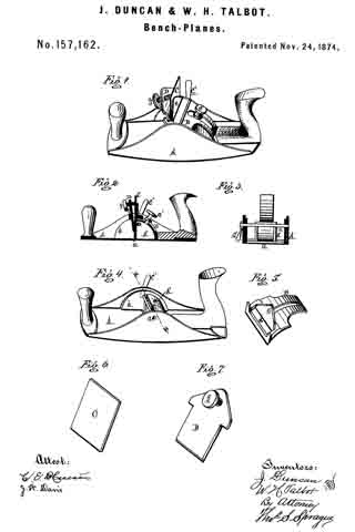
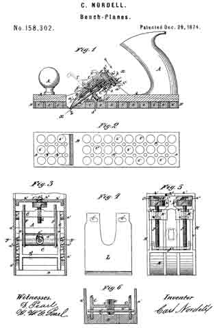
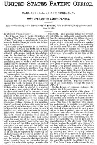
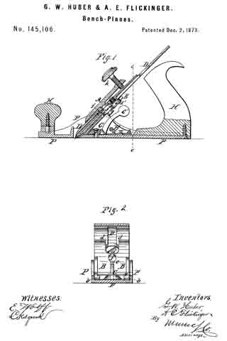
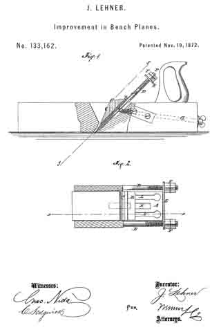
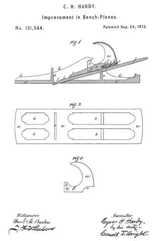
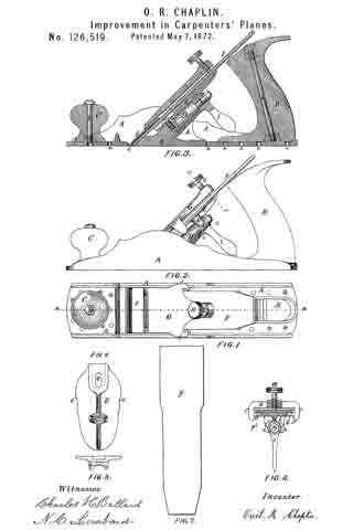
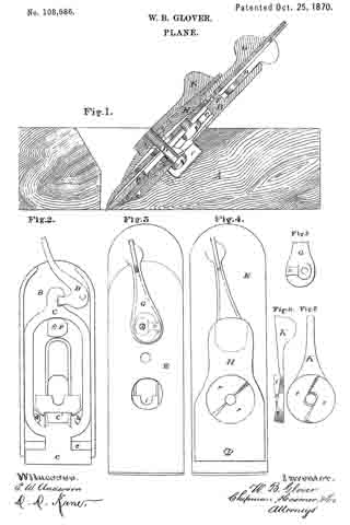
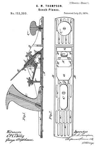
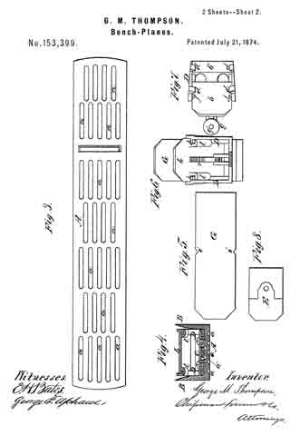
Figure 1 of the drawing is a representation of a longitudinal vertical section of my plane. Fig. 2 is a top plan view, and Fig. 3 is a bottom plan view. Fig. 4 is a transverse section, and Figs. 5, 6, and 7 are detail views. Fig. 8 is an under-side view of the chip E.

This invention has relation to that class of bench-planes having metallic stocks; and it consists, principally, in a bed-frame and moveable carriage for the plane-iron, which carriage is adjustable by means of a rack and segment lever and a thumb-screw, and affords a broad and firm bearing for the plane-iron. It further consists in combining, with the plane-iron and its adjustable bed, a jointed “chip” or wedge, which is provided with a set-screw, by means of which the upper and lower ends of the said chip can be made to bear with considerable force upon the plane-iron, and rigidly hold it in place. My invention consists, further, in constructing V-shaped lugs on the plane-iron carriage, which lugs are adapted to enter notches made in the edges of the plane-iron, and thereby prevent the same from slipping longitudinally when adjusted on its carriage, as will be hereinafter more fully explaned.

The following is a description of my improvements:

In the annexed drawings, A designates a sole-plate, and B B the side flanges or cheeks thereof, which, with the plate, constitute a metal plane-stock, which is cast entire. C and C’ designate the handles of the stock, which are of the usual well-known form, and are secured on top of the sole-plate in any suitable manner. The bottom and top surfaces of the sole-plate are constructed with numerous grooves, a, arranged alternately in regular rows of short sections, which greatly reduce the frictional surface, while at the same time they lighten the stock very much. The grooves a’ on top of the sole-plate are disposed between the grooves a, and also lighten the stock without materially reducing its strength or stiffness. The said grooves run in a direction with the length of the stock, and they are preferably made quite short, so that they will not interfere with the dressing of the edge of a very narrow piece of stuff. D designates a frame, which is rigidly secured upon the sole-plate A, in rear of the throat, by means of a clamp, c. This frame D is constructed with a bearing, b’, for the lower portion of the plane-iron G, the upper portion of which iron is supported upon an inclined carriage or sliding bed, b. This carriage b is guided in the frame D by means of lips p p and hooking-lugs l l, (shown in Fig. 6,) and it is constructed with V-shaped lugs j j, which enter notches i i made in the edges of the plane-iron G, and thus prevent endwise displacement of the plane-iron on its carriage. On the bottom side of the carriage b a rack, r, is formed, the teeth of which engage with a toothed segment, which is formed on the short arm of a lever, F, which has its fulcrum at f on standard h, rising from the base of the frame D. The longer arm of lever F is forked, and embraces an annular groove in an adjusting-nut, g, which nut is applied on a screw, g’, rising perpendicnlarly from a rear extension of the base of frame D. By adjusting the nut g, the carriage b can be moved up and down in the frame D, and the plane-iron can be nicely adjusted according to the thickness of the shaving required. E designates what is denominated the chip, which is of wedge form, and composed of two pieces hinged together at e’, and provided with a set-screw, e. When the plane-iron G is in place on the carriage b and bearing b’, the chip is inserted between it and four hooked lugs, d d d d, after which the parts are rigidly secured in place by means of the screw e, which bears on the plane-iron, and, by centrally bowing up the joint e’, forces the ends of the chip hard down on the plane-iron, as indicated in Fig. 1.

I am aware that similar devices have heretofore been used, as shown in the patent of Leonard Bailey, dated August 6, 1867, No. 67,398, and therefore I do not make claim to any device therein shown.

What I claim as new, and desire to secure by Letters Patent, is —

1. The frame D, constructed with a bed-piece, b’, and provided with an adjustable carriage, D, for the plane-iron provided with the rack r, and combined with cogged segment-lever F and adjusting-nut g, substantially as and for the purpose described.

2. The jointed chip E, provided with a set-screw, e, combined with the frame-lugs d, and the plane-iron G upon its carriage b, arranged as described.

3. The carriage b, provided with lugs j, combined with al plane-iron having notches i i in the edges to correspond therewith, substantially as in the manner shown and described.

In testimony that I claim the above I have hereunto subscribed my name in the presence of two witnesses.

GEO. M. THOMPSON.

Witnesses:
GEORGE E. UPHAM,
FRANK J. MASI.

No. 157,162 – Improvement In Bench-Planes (James Duncan And William H. Talbot) (1874)

[paiddownloads id=”234″]157162


UNITED STATES PATENT OFFICE.

_________________

JAMES DUNCAN AND WILLIAM H. TALBOT, OF BUCHANAN, MICHIGAN.

IMPROVEMENT IN BENCH-PLANES.

_________________

Specification forming part of Letters Patent No. 157,162, dated November 24, 1874; application filed June 17, 1874.

_________________

To all whom it may concern:

Be it known that we, JAMES DUNCAN and WILLIAM H. TALBOT, of Buchanan, in the county of Berrien and State of Michigan, have invented a new and useful Bench-Plane for Scraping Veneers, of which the following is a specification:

The nature of our invention relates to the combination, with a small metallic plane-stock, of a scraping-bit, and certain devices for securing the said bit at any angle or inclination with the plane-throat; and it consists in the peculiar construction and arrangement of the devices for adjusting and securing the scraping-bit in the plane-stock, as more fully hereinafter set forth.

Figure 1 is a perspective view. Fig. 2 is a longitudinal vertical section through the center of the tool. Fig. 3 is a cross-section at x x, in Fig. 4, which is a perspective view of the plane-stock, the bit, segment, and pressure-plate being removed. Fig. 5 is a perspective view of the segment. Fig. 6 is a similar view of the scraper-bit. Fig. -7 is a similar view of the pressure-plate and screw.

In the drawing, A represents a small metallic plane-stock, having the form of the metallic smoothing-plane in common use, provided with the usual handles, and with a transverse throat, a. To the inner side of each cheek is secured or formed therewith a semi-circular shoulder, b, in the radius of the throat a, from which the circle is struck. In the middle, and behind the throat, a shell-like quadrant, A’, rises from the flat of the plane-stock, having the same radius as the shoulders b. c is a screw-threaded bolt tapped through the cheek of one side of the plane-stock, passing through the quadrant and the other cheek, where it receives on its threaded protruding end a tail-nut, C’, by means of which the cheeks may be slightly sprung toward each other, and thus clamp anything fitted between them. B is a sliding segment lying on the shoulders b b and quadrant A’, to the latter of which it may be secured at any point by a set or clamp screw, c’, passing through a longitudinal slot in the segment, and tapped into the quadrant. The segment is still more firmly secured by clamping its sides between the cheeks of the plane-stock by means of the screw c and nut C’. In the fore end of the segment is a transverse slot, d, from the back of which rises a plate, e, which serves as a rest for the steel scraping-bit C which is inserted in the slot, its lower end projecting through the throat a. In front of the bit a pressure-plate, D, is inserted in the slot. A set-screw, f, is tapped through the top of the plate D bearing against the bit, as does the lower edge of said plate D, forcing the bit against the bearing-plate e, thus securing the scraping-bit to the segment B, the former being adjusted to take more or less cut, like an ordinary plane-iron, while it may be adjusted to a vertical position or to any inclination with relation to the work without altering its set, an essential feature in finishing veneers of different woods and structure of fiber or grain.

What we claim as our invention, and desire to secure by Letters Patent, is —

1. The combination, with the plane-stock A having the throat a, of the shoulders b, quadrant A’, segment B, scraper-bit C, pressure-plate D, and screws c’ f, substantially as and for the purpose set forth.

2. The combination, with the plane-stock A, of the shoulder b, quadrant A’, segment B, bolt c, nut C’, scraping-bit C, pressure-plate D, and screws c’ f, as and for the purpose set forth.

JAMES DUNCAN.
WM. H. TALBOT.

Witnesses:
L. P. FOX,
JAMES K. WOODS.

No. 157,438 – Improvement In Block-Planes (Charles Bridges) (1874)

[paiddownloads id=”235″]157438


UNITED STATES PATENT OFFICE.

_________________

CHARLES BRIDGES, OF LOWELL, MASSACHUSETTS.

IMPROVEMENT IN BLOCK-PLANES.

_________________

Specification forming part of Letters Patent No. 157,438, dated December 8, 1874; application filed July 28, 1873.

_________________

To all whom it may concern:

Be it known that I, CHARLES BRIDGES, of Lowell, in the county of Middlesex and Commonwealth of Massachusetts, have invented certain Improvements in Block-Planes, of which the following is a specification:

My invention relates to a metallic block-plane; and consists, first, in the shape of the handle, and, second, in the means of securing said handle and the plane-iron to the stock, as hereinafter described.

In the accompanying drawings, Figure 1 is a general section of my improved plane. Fig. 2 is a rear view of the same. Fig. 3 is a perspective view of the handle, slotted wedge-plate, post, and inclined cap; and Fig. 4 is a view ofthe handle, slightly modied, and another form of wedge-plate.

A is the metallic stock, having the top of its sides parallel with the bottom thereof, and having an upright post, C, cast in one piece with it. Upon the top of said post is cast a cap, E, the under side of which cap inclines toward the throat. The plane-iron herein used is the ordinary slotted plane-iron F. The post C and cap E are passed up through the broad part of the slot in the plane-iron F, and said iron rests upon the beveled side of the throat, and upon a partition, L, which runs across the stock A, in the usual manner, back of said post C.

The plate I is just wide enough to fll the space between the sides of the stock, is nearly twice as long as broad, has straight parallel sides, is straight in front and rounded out behind, and has in the middle a longitudinal slot wide enough at its front end to allow the cap E to pass up through the plate; but the rest of the slot is only wide enough to admit the post C below said cap. On each side of the narrow part of said slot are cast wedges D, which have the thin end in front. Said plate I is turned up about three-eighths of an inch in front, and is secured to the handle B by screws passing through the ends of said plate.

The top of the handle B is curved backward from the front of said wedge-plate I to the back of the same, its greatest elevation being near the back of said handle. The base of said handle is shaped like said wedge-plate, but is wider. The sides of the base of said handle are parallel with, directly over, and nearly touch the top edges of the stock A. The handle above its base is broader than the stock, the sides and top of said handle being convex, so that said sides project beyond the stock. The plate I makes such an angle with the bottom of said handle that, when the handle is in the position described, said plate lies flat on the plane-iron F.

From the above description it will be seen that driving the handle forward crowds the wedges D on the plate I under the cap E, and holds the plane-iron F in place.

The transverse partition J, immediately in front of the throat, is commonly used as a finger-rest; but for this purpose I use the hollow panel G in the space between said partition and the rim at the front end of the stock.

A modification of my invention is shown in Fig. 4, consisting of the handle B’ and wedge-plate I’ cast in one piece, and connected at the sides, and also by the post N’, which stands above the plate, and is divided where it joins said plate on each side of the wedges D’. This plate I’ is like a piece of the plate I shown in Figs. 1 and 3, cut out around the wedges. The handle B’, Fig. 4, is brought down in front, so as to fill the space above the plane-iron, in order to bear upon said iron. In all other respects the handle, plate, and wedges shown in Fig. 4 are like those already described.

The advantages of my invention are, that the handle offers a continuous curved surface to the hand; that its sides, projecting beyond the stock, enable it to be firmly and readily grasped; that, being entirely closed, it does not catch dust and shavings, and that the plane-iron is very easily removed or placed in position.

I claim as my invention —

1. The handle B, as and for the purpose herein shown and described.

2. The combination of the handle B, the wedge-plate I, having the wedges D, the post C, the cap E, the slotted plane-iron F, and the stock A, as and for the purpose herein specified.

CHARLES BRIDGES.

Witnesses:
ALBERT M. MOORE,
IRVING S. PORTER.

No. 158,302 – Improvement In Bench-Planes (Carl Nordell) (1874)

[paiddownloads id=”236″]158302


UNITED STATES PATENT OFFICE.

_________________

CARL NORDELL, OF NEW YORK, N. Y.

IMPROVEMENT IN BENCH-PLANES.

_________________

Specification forming part of Letters Patent No. 158,302, dated December 29, 1874; application filed June 18, 1874.

_________________

To all whom it may concern:

Be it known that I, CARL NORDELL, of the city of New York, in the county and State of New York, have invented certain Improvements in Bench-Planes, of which the following is a specification:

The object of my invention is to furnish a hand-plane in which the tooth can be used shorter than in other planes, held in place and adjusted to the proper depth of cut and clearance for the shavings without the use of a double or covering tooth, or of the ordinary wedge, or the necessity of adjustment by hammering, and in which a durable metallic surface may be employed without liability of sticking to the surface of the work in consequence of the adhesion resulting from the well-known affinity between the metal and the rosin of the wood.

To accomplish this the invention consists, first, in a metallic cap, adjustable by means of a screw, or equivalent, to give the desired clearance for the shavings, and tightened against the tooth by means of a cam-lever pivoted to a screw adjusted in a threaded socket, which socket is pivoted on a spring-wire, or equivalent spring, which latter, held in permanent position at its two ends, allows ofa yielding at its middle to any extra or over pressure of the cam on the cap. This cap, with the cam-lever, thus does the purpose of the ordinary double or covering tooth and tightening-wedge. Second, in the combination of stationary springs with movable and adjustable screw-slides operating in the cap, and provided with cleats and stops, in such a manner that, when the cam-lever is thrown forward to loosen, but not remove, the cap, the tooth, which is provided with holes or slots suitable to encompass the said cleats, when the upper end of the tooth reaches the said stops, may be easily inserted between the said springs and the slides, and when pushed up against the said stops will be lodged on the said cleats by the pressure of the said springs, after which the depth of the tooth, or of the cut, is regulated. by operating the slides by means of its screws pivoted in the cap. When the cam is loosened the tooth may be instantly removed, when required, by simply pressing down the rear end of the cap against the ends of the springs placed under the tooth. This pressure raises the forward end of the cap sufficiently to release the tooth from the cleats, and allow it to slide out through the opening in the face of the plane. Third, in providing a combined metallic and wooden face of a plane by perforating or socketing the metallic face-plate, and inserting in the holes or sockets so formed one or more diffferent kinds of hard wood, placed with its grain or fibers at right angles to the face of the plane.

In the accompanying drawing, making a part of this specification, Figure 1 represents a longitudinal vertical section of a metallic hand-plane for planing wood, constructed according to my present invention. Fig. 2 is a face view of the same. Fig. 3 is a cross-section of the same, taken through the line x x of Fig. 1, and seen in direction of the arrow. Fig. 4 is a plan view of the under side of the tooth ofthe plane. Fig. 5 is a plan view of the inside of the cap, with its slides and screws for adjusting the tooth. Fig. 6 is a cross-section of the plane, taken through the line y y of Fig. 3.

Similar letters of reference indicate like parts in the different figures.

A are the wooden handles of the plane. B is the metallic face-plate, provided at each edge with upright flanges a1, between which are inserted and secured as well the handles A as the entire mechanism for operating the tooth. The face B is provided with numerous perforations or sockets, into which are tightly in serted the wooden pieces b’, made of any desired shapes and sizes, in such a manner as to form a perfectly smooth and even surface with the metal. C is a metallic frame for supporting the tooth, cap, springs, and sockets, severally above mentioned, and the screw for regulating the cap to give the desired clearance for the shavings. The frame C is provided on the outside with cleats c1 c2, and is of sufficient width outside of the cleats to snugly fill the space between the flanges a1, and is secured to the metal of the plane by entering the cleats c2 tightly between the two cleats a2 a3, formed on each side of the frame C upon the inner sides of the flanges a1, and is fastened at the bottom to the top of the metallic face-plate B by a pin, c3. The frame G may also be secured in any other suitable manner, the mode being immaterial so long as it be held firmly in its place. D are ribs or upright flanges of the frame C, upon which flanges the tooth rests when in position for work. A part of the lower portion of the frame C is formed into a socket, d1, placed across the face-plate of the plane, through which socket, and through holes in the lower part of the flanges D, is inserted a wire spring, d2, which spring also goes through and serves as pivot for the screw-socket E. This socket E is held in a central position in the frame C by being inserted through an oblong hole, e’, in the frame G, previous to the insertion, through the socket E, of the spring d2 The hole, being oblong, allows of an oscillating motion of the socket E, and thus also of a sliding motion of the cap. F are springs attached, with their lower ends, to the bottom of the frame C, and bearing, with their upper ends, against the under side of the tooth, to force the same, when being inserted, into its proper position against the cap, and retaining it there, even when the cap is partly released for adjustment of the cap or of the tooth. The upper cross-bar of the frame C is provided with a threaded hole for the reception of a thumb-screw, G, on which are formed a thumb-nut or milled wheel, g1, a shank, f1, and a button, g2. H is the cap, curved so as to touch with its forward end the lower or forward end of the tooth, whatever be the adjusted position of the cap. The rear end of the cap is formed into a downward-projecting flange, h1, in which is a slot, h2, fitting, when the cap is placed in position on the shank f1, between the thumb-nut g1 and button g2 of the screw G, the circumference of the thumb-nut g1 projecting far enough below the edge of the flange h1 to allow of turning the screw G, whereby the cap H is slid forward or withdrawn, according to the clearance desired for the shavings. In about the center of the cap H is a cup-shaped slotted socket for the reception of the spherical cam of the cam-lever I. This cam is slotted, and in its slot is pivoted the upper end of a screw, l’, the lower end of which enters the socket E. The cap H is also provided, at its upper or rear end, with slots h3, through which project, sufiiciently far to handle, the thumb-nuts j1 of the screws J. The forward ends of the screws J are pivoted in a rib, j2, forming a part of or attached to the cap H. The rear ends of the screws J are pivoted to the pieces i1, attached to the rear end of the cap H. On these pieces i1 are little projections i2, forming a cavity between them, for the reception of the rear ends of the springs F. K are slides, each threaded to form a nut, for the reception of one of the screws J, by turning which they are operated. Each slide K is provided with a cleat, k1, and a stop, k2. L is the tooth, the center of which is cut out so as to allow of its being slid back and forth without interfering with the screw I’ or socket E. In the rear ends of the tooth L are perforations l’, to receive, when the tooth is inserted, the cleats k1 of the slides K.

When the cam-lever is thrown in the position indicated by the dotted lines in Fig. 1, the springs F will raise the cap H sufliciently to allow (while slightly depressing the rear end of the cap H) of the introduction of the tooth L until it is checked by the stops k2 on the slides K. Allowing the springs F to expand, the tooth will be brought, with its slots l’, onto the cleats k1. By now turning either or both screws J, as the circumstances may require, by the hand-nuts j1, the tooth can be adjusted to the depth required, and its edge parallel to the face of the plane. The cap H is then adjusted by the screw G and hand-nut g1, to give the right clearance fbr the shavings. The cam-lever I is then tightened to depress the cap H, and the plane is ready for work.

Should the screw I’ have been turned down in its socket E too far for suiting a thicker tooth, the spring d2 will make up for the difference by yielding enough to allow of bringing the cam-lever down to the surface of the cap H in tightening the cam.

To remove the tooth it is only necessary to loosen the cam and depress slightly the rear end of the cap H.

Having thus described my invention, I claim as new and desire to secure by Letters Patent —

1. The cam and lever I, screw I’, and socket E, in combination with the spring d2, operating as described, and with the cap H, to hold the tooth firmly in place against the ribs D of
the frame C, substantially as specified.

2. The springs F, operating as described, in combination with the pieces i1 on the curved cap H, and the parts I I’ E, for the insertion and removal of the tooth L, and retaining the same while being adjusted, substantially as and for the purpose specified.

3. The screws J, working in the cap H, and provided with thumb-nuts j1, the slides K, with their cleats k1, and stops k2, in combination with the tooth L, provided with the slots l’, for the purpose of adjusting its position, substantially as and for the purpose specified.

4. The cap H, regulated by the screws G, the tooth L, regulated by the screws J and slides K, the cam and lever I, screw I’, socket E, and springs d2 F F, in combination with the frame C, face B, and handles A of a plane, to operate together in the manner and for the purposes substantially as specified.

5. The face of a plane, constructed by inserting pieces of wood b’ in a metallic face-plate, B, with the fibers at right angles to the face, substantially as and ibr the purpose specified.

The above specification of my invention signed by me this 15th day of June, 1874.

CARL NORDELL.

Witnesses:
D. PEARL,
H. W. E. PEARL.

No. 138,591 – Improvement In Planes (J. Ceville Spencer) (1873)

[paiddownloads id=”210″]138591


UNITED STATES PATENT OFFICE.

_________________

J. CEVILLE SPENCER, OF PHELPS, NEW YORK, ASSIGNOR TO HIMSELF
AND FRANCIS X. GERVIS, OF SAME PLACE.

IMPROVEMENT IN PLANES.

_________________

Specification forming part of Letters Patent No. 138,591, dated May 6, 1873; application filed March 1, 1873.

_________________

To all whom it may concern:

Be it known that I, J. CEVILLE SPENCER, of Phelps, in the county of Ontario and State of New York, have invented a new and useful Improvement in Planes, of which the following is a specification:

Figure 1 is a bottom or face view of my improved plane. Fig. 2 is the same view as Fig. 1 with the adjustable plate removed. Fig. 3 is a detail longitudinal section of the same taken through the line x x, Fig. 1. Fig. 4 is a detail cross-section of the same taken through the line y y, Fig. 1. Fig. 5 is a detail top view of the adjusting-lever.

Similar letters of reference indicate corresponding parts.

My invention has for its object to furnish an improved plane which shall be so constructed that it may be conveniently, quickly, and accurately adjusted to cnt a thicker or thinner shaving, as may be desired. The invention consists in the improvement of planes, as hereinafter described and pointed out in the claims.

A represents an ordinary plane-stock. B are the plane-irons, and C is the wedge by which the said irons are secured in the said stock. D is a plate, which is placed in a recess in the face of the plane-stock A in front of the edge of the plane-irons B, and which is so arranged as to move longitudinally with the plane-stock, but not laterally. The recess in which the plate D is placed is made deeper than the thickness of the said plate, which plate rests upon the heads of four or more screws, E, screwed into the said stock A in the bottom of the said recess, as shown in Figs. 2, 3, and 4, and in dotted lines in Fig. 1.

By this construction when it becomes necessary to dress off the face of the plane-stock A the screws E are turned in a little so that the recess does not have to be deepened every time the face of the plane-stock is dressed off. The plate D is secured in place by a bolt, F, the head of which is countersunk into the plate D, and which passes up through the plane-stock A and has a hand-nut, G, screwed upon its upper end. The hole through the plane-stock A is made larger than the bolt F, and in it is placed a collar, H, through which the bolt F passes, and which is countersunk from each side to adapt it to serve as a fulcrum to the bolt F to enable said bolt to be used as a lever for adjusting the plate D when the nut G has been loosened. I is a plate let into the stock A in the bottom of the recess in said stock, and in which is formed a hole for the passage of the bolt F. In the plate I at one side of the hole through said plate is formed a notch to receive a toe, f’, formed upon the side of the bolt F to serve as a fulcrum, so that the plate D may be moved to adjust it by turning the bolt F. The upper part of the bolt F is flattened to receive the forked end of the lever J, which is placed between the stock A and the-nut G.

By this construction, by loosening the nut G and operating the lever J the plate D may be adjusted as required.

Having thus described my invention, I claim as new and desire to secure by Letters Patent —

1. The combination of the bolt F, hand-nut G, and fulcrum-collar H with the plane-stock A, and adjustable plate D, substantially as herein shown and described.

2. The combination of the perforated and notched stationary plate I, toe f’, and forked lever J with the plane-stock A, adjustable plate D, bolt F, and nut G, substantially as herein shown and described.

J. CEVILLE SPENCER.

Witnesses:
LYSANDER REDFIELD,
FRANCIS GERVIS.

No. 144,381 – Improvement In Bench-Planes (William H. Brown And David F. Williams) (1873)

[paiddownloads id=”219″]144381


UNITED STATES PATENT OFFICE.

_________________

WILLIAM H. BROWN, OF WORCESTER, MASSACHUSETTS, AND DAVID F.
WILLIAMS, OF WOONSOCKET, ASSIGNORS TO BAILEY TOOL COMPANY, OF WOONSOCKET, RHODE ISLAND.

IMPROVEMENT IN BENCH-PLANES.

_________________

Specification forming part of Letters Patent No. 144,381, dated November 11, 1873; application filed April 12, 1873.

_________________

To all whom it may concern:

Be it known that we, WM. H. BROWN, of Worcester, in the county of Worcester and State of Massachusetts, and DAVID F. WILLIAMS, of Woonsocket, in the county of Providence and in the State of Rhode Island, have invented a new and useful Improvement in Bench-Planes; and we do hereby declare that the following is a full, clear, and exact description thereof, reference being had to the annexed drawings making a part of this specification, in which —

Figure 1 represents our improved bench-plane in perspective, and Fig. 2 a vertical longitudinal section of the same.

Our invention consists in certain hereinafter-described means provided for the purpose of facilitating the adjustment of the cap, and for regulating the pressure upon the cutting-tool.

The general construction of our bench-plane is like that described in Letters Patent No. 105,767, granted Joseph R. Bailey, July 26, 1870, an eccentric or curved bar, A, being used in conjunction with a presser-plate, B, to secure the plane-iron D and intervening cap C in the stock E. The presser-plate in this case is elongated and provided with a head, D, and a set-screw, d, the former of which acts in conjunction with other parts presently to be described, while, by means of the lathe, the pressure of said plate against the cam-rod may be adjusted so as to permit of the use of a thick or thin cap or cutting-iron, as desired. It also has lugs e, which project into grooves f cut in each side of the flanges of the stock, at right angles to the cutting-tool, whereby the slipping or sliding of the plate forward or backward is prevented, while at the same time it is allowed to rise and fall under the action of the set-screw d. The accurate adjustment of the cap with reference to the cutting edge of the chisel and the throat of the stock is obtained by means of a set-screw, F, which is carried in a screw-threaded eye in ear c of the cap, and bears with its point against the head b of the presser-plate. The foot of set-screw F being pointed, as shown, a V-shaped groove is formed in the end of head b, to receive such point, and allow the presser-plate to rise and fall and keep it in its exact position.

In the adjustment of the parts, the cap should be properly arranged by adjusting the set-screw F before the eccentric bar is turned down to force the presser-plate against the cap.

We claim as our invention —

1. In a bench-plane of the character described, an adjusting-screw, F, working in an ear, c, formed on or attached to the cap, combined with the presser-plate B, provided with the grooved head b, substantially as and for the purpose set forth.

2. The eccentric A, presser-plate B with lugs e e, grooves f f, and set-screw d, in combination with the cap or plane-iron.

3. The presser-plate B, with lugs e e, in combination with cap C c, set-screw F, and grooves f f substantially as described.

In testimony that we claim the above-described improvement we have hereunto signed our names this 5th day of April, 1873.

WM. H. BROWN.
DAVID F. WILLIAMS.

Witnesses:
F. T. BLACKMER,
W. W. RICE.

No. 144,823 – Improvement In Metallic Planes (Joseph F. Baldwin) (1873)

[paiddownloads id=”220″]144823


UNITED STATES PATENT OFFICE.

_________________

JOSEPH F. BALDWIN, OF BOSTON, ASSIGNOR TO JOHN SULLY, TRUSTEE, OF DEDHAM, MASSACHUSETTS.

IMPROVEMENT IN METALLIC PLANES.

_________________

Specification forming part of Letters Patent No. 144,823, dated November 25, 1873; application filed June 7, 1873.

_________________

To all whom it may concern:

Be it known that I, JOSEPH F. BALDWIN, of Boston, in the county of Suffolk and State of Massachusetts, have invented certain Improvements in Metallic Planes, of which the following is a specification:

Figure 1 of the accompanying drawings is a central vertical longitudinal section of my improved bench-plane. Fig. 2 is a top view of the plane-wedge.

The present invention relates to certain new and useful improvements in bench-planes, particularly applicable to metallic planes, and having for their principal objects the providing of a simple and convenient means of regulating, so as to vary, the cut of the plan-iron. My improvements consist, mainly, in a metallic or other suitable carriage, arranged and operated, as will be hereinafter more fully described, to travel on an inclined screw-rod, and raise or lower the plane-iron so as to vary its cut, as desired.

In the drawings, a represents the bottom, and b the sides, of the plane. c is the mouth, forward of which is an upright transverse plate or finger -bar, d. The bottom a has formed on, or attached to, the top in the center a boss, e, that tapers upward to receive and hold one end of an inclined rod, s, which extends upward through a transverse vertical plate, f connecting the two sides b at the rear of the center of the plane, and notched on the top at the center to allow of the forward and back inclined travel of a metallic or other suitable carriage, g, formed at the top end with a downward-extending flange, g’, bifurcated at the end to straddle a screw-nut, h, formed with a groove, g”, to receive and hold the flanged end g’, and having female screw-threads that mesh with male screw-threads formed on the upper portion of the inclined rod s, which receives on its smooth or lower portion, so as to allow the travel of a flange, i, that depends from the under side of the lower or forward portion of the carriage, g, which is provided on the top near the lower end with an upward-extending stem, k, that fits into an aperture, l’, formed in the iron, l, which may, if desired, be supplied with one or more supplementary apertures, l”, to allow of the wear of the iron, which may thus be placed either higher or lower on the carriage g. The sides b are formed with, or have attached to them, at a suitable distance above, and at the rear of the mouth, lugs m, between the bottom of which and the top of the iron l is inserted the lower portion of a metallic or other suitable wedge, n, the bottom of which is countersunk, and at the upper portion is made open, as shown in Fig. 2, leaving its sides n” to project rearward and upward to form a curved shield, n’. The top edge of the wedge proper is curved, as shown at o, Fig. 2, and formed in the center with a screw-socket, q, that receives a thumb-screw, p, that is operated against the top of the iron l, so as to raise the upper end of the wedge n, which, acting as a lever, with the lugs m as a fulcrum, causes the bottom of the wedge to bear firmly on the top of the lower end of the iron l, which is thus securely held in position; or, by loosening the screw p the iron l is released, so as to allow of its being raised or lowered to suit the desired cut, or to be withdrawn for sharpening or replacement, &c.

It will readily be seen by the above description, reference being had to the accompanying drawings, that the screw-nut h, turning on the screw-end of the rod s, carries the carriage g, connected with the rod s and nut h by the flanges g’ i, up and down, thus raising or lowering, according to the direction in which the nut is turned, the iron l, which is connected by the stem k with the carriage, by whose operation it is thus readily adjusted to the desired cut.

In a large plane the extended sides n” and the shield portion of the wedge are dispensed with, and the curved top portion of the wedge is extended and formed in the shape shown in Fig. 4, with a central screw-socket, q, for the reception of a screw, p.

Having thus fully described my improvements, what I claim as my invention, and desire to have secured to me by Letters Patent, is —

The carriage g, provided with the flanges g’ i and stem k, in combination with the plane-iron l having orifices l’ l”, the nut h having the groove g”, and the screw-rod s, all arranged and operating substantially as described.

In testimony whereof I have hereunto signed my name to this specification in the presence of two subscribing witnesses.

JOSEPH F. BALDWIN.

Witnesses:
SAML. M. BARTON,
CARROLL D. WRIGHT.

No. 145,106 – Improvement In Bench-Planes (George W. Huber And Aaron E. Flickinger) (1873)

[paiddownloads id=”221″]145106


UNITED STATES PATENT OFFICE.

_________________

GEORGE W. HUBER AND AARON E. FLICKINGER, OF NORWALK, OHIO.

IMPROVEMENT IN BENCH-PLANES.

_________________

Specification forming part of Letters Patent No. 145,106, dated December 2, 1873; application filed October 18, 1873.

_________________

To all whom it may concern:

Be it known that we, GEORGE W. HUBER and AARON E. FLICKINGER, of Norwalk, in the county of Huron and State of Ohio, have invented a new and Improved Plane, of which the following is a specification:

In the accompanying drawing, Figure 1 represents a vertical longitudinal section of our improved plane; and Fig. 2, a vertical transverse section of the same on the line c c, Fig. 1.

Similar letters of reference indicate corresponding parts.

The object of our invention is to construct an improved plane, which is light, handy, and easily adjustable to any thickness of shaving without the use of a hammer. Our invention consists in the firm mounting of the plane-iron between a cap-piece with connecting clamping-bolt and set-screw, and a supporting-shoe, which is pivoted to the sides of the base-piece, and adiusted, together with the plane-iron, by a conical eccentric pivoted to the base.

In the drawing, P represents the base-piece of the plane, provided with front and rear handles H, and made preferably of cast-iron. The shoe B is pivoted at a to the side flanges of base A, and supports on its inclined front part the plane-iron D, while the backward-extending bracket-shaped sides rest with their broader ends on rubber cushions b, by which a certain degree of spring action is imparted to shoe B, so as to offer a yielding support to the plane-iron. The face part of shoe B is provided with a recess, d, and extension-slot e, for giving play to the screw-head d’ of the plane-iron D and clamping-bolt f of the cap-piece A. The plane-iron D has a perforation, f’, for the passage of bolt f. A conical eccentric, C, is pivoted to a lug, g, of base P, under the lower extremity of shoe B, and produced under the same inclination of its sides as the front part of shoe B, so as to raise or lower shoe B, as the eccentric C is turned, by means of its handle C’. The plane-iron is thus raised or lowered with shoe B, and the thickness of the planing regulated thereby. The slot through which the plane-iron projects is widened on lowering the iron, so that the thicker shavings may freely pass through the same; while, in raising the iron, the slot is narrowed in proportion to the thinner shavings, and thus the tearing up of the wood or the veneers prevented, and a neat and smooth surface produced. The cap-piece A is placed on the top of the plane-iron D, its clamp-bolt f passing through the slotted part of the iron and into slot e of shoe B. The sides of bolt f are recessed to correspond exactly to the width of slot e, while its broad head projects over the sides of slots e, and holding thereby the plane-iron and shoe in position. By means of a set-screw, h, at the upper end of cap A, the shoe B may be firmly tightened on the iron D, clamping it rigidly between cap A and shoe B. The plane iron is in this manner easily and firmly set into the plane, and readily adjusted to any degree of planing in a neat and convenient manner, economizing time, and forming a compact and strong implement for the trade.

Having thus described our invention, we claim as new and desire to secure by Letters Patent —

The improved adjustable plane, consisting of base-piece P, pivoted shoe B with rubber cushions b, conical eccentrics C C’, perforated plane-iron D, and clamping cap~piece A, constructed substantially as and for the purpose as described.

GEORGE W. HUBER.
AARON E. FLICKINGER.

Witnesses:
E. R. JACKSON,
T. H. KELLOGG.

No. 145,311 – Improvement In Plane-Irons (Ernest Quast) (1873)

[paiddownloads id=”222″]145311


UNITED STATES PATENT OFFICE.

_________________

ERNEST QUAST, OF JERSEYVILLE, ILLINOIS.

IMPROVEMENT IN PLANE-IRONS.

_________________

Specification forming part of Letters Patent No. 145,311, dated December 9, 1873; application filed February 18, 1873.

_________________

To all whom it may concern:

Be it known that I, ERNEST QUAST, of Jerseyville, in the county of Jersey and State of Illinois, have invented a new Improvement in Plane-Irons; and I do hereby declare that the following is a full and exact description of the same, reierence being had to the accompanying drawings, and to the letters of reference marked thereon.

This invention is a plane-bit having a shank of cast malleable iron, or common wrought-iron, and a removable cutting-edge of steel, the same constituting a new article of manufacture, as will be fully described hereafter.

In the drawing the plane-bit is shown in perspective.

A represents the upper section of the bit, of the usual form, and is made of iron, preferbly cast malleable iron. B is the cutting-part, made of suitable cast-steel. C is a screw or rivet, by which the parts are held together. a a’ are overlapping tongues, shaped to engage with each other, so as to form a scarf-joint of the two parts A and B. It will be seen that where the two parts A and B butt together at d and d’, the edge d is square, while d’ is beveled. Both may, however, be beveled, if so preferred.

When the steel part B is worn out, it can be quickly and easily removed by taking out the screw or rivet C. The part A, in consequence of being subject to but little wear, may thus be made to serve for almost an unlimited number of steel bits. It therefore follows that these plane-bits constructed as described, possess all the advantages of those made entirely of steel, and can be produced as cheaply as those made of steel and iron welded together, without that deterioration in the quality of the steel which is almost inseparable irom the process of welding.

Having fully described my invention, what I claim as new, and desire to secure by Letters Patent, is —

The plane-bit described, having the iron shank A and steel cutting-part B, as a new article of manufacture.

This specification signed and witnessed this 5th day of February, 1873.

ERNEST QUAST.

Witnesses:
JAMES A. LOCKE,
DENNIS BROWN.

No. 133,162 – Improvement In Bench-Planes (Jacob Lehner) (1872)

[paiddownloads id=”204″]133162


UNITED STATES PATENT OFFICE.

_________________

JACOB LEHNER, OF GALENA, ILLINOIS.

IMPROVEMENT IN BENCH-PLANES.

_________________

Specification forming part of Letters Patent No. 133,162, dated November 19, 1872.

_________________

To all whom it may concern:

Be it known that I, JACOB LEHNER, of Galena, in the county of Jo Daviess and State of Illinois, have invented a new and useiul Improvement in Bench-Planes, of which the following is a specification:

My invention consists of a combination of screw-rods, nuts, and an adjusting-bar, with the plane stock and bit, in such manner that the setting of the plane-bit is effected by turning the nuts on the screw-rods, the latter being attached to the plane-stock at each side parallel with the bit. My invention also consists of a combination of a tightening-rod with the wedge and plane-bit for securing and releasing the latter; the said rod passing from the heel of the plane-stock through the plane-bit and its cap, which are slotted at the center for the purpose, into the wedge, in which it screws, and the plane-bit having two other slots, one at each side of the center slot, for the screws, by which the cap is secured to it, to allow the tightening-rod to pass through the center slot.

Figure 1 is a longitudinal sectional elevation through my improved plane on the line x x of Fig. 2, and Fig. 2 is a section on the line y y of Fig. 1.

Similar letters of reference indicate corresponding parts.

A is the plane-bit; B, the cap; C, the wedge; D, the screw-rods; E, the cross-bar; and F, the adjusting-nuts. The said rods are attached to the plane-stock, one at each side of the plane-bit, parallel with it, and extend a little higher than the bit does; the cross-bar fits on the rod above the plane-bit, so as to force it down by the adjusting-nuts F, which screw on the rods above the bar, two being used on each rod to fasten one by the other. G is the tightening-rod for fastening the bit and wedge; it passes from the heel of the stock, where it is provided with a thumb-bit for turning it, through the stock to the throat, and through the plane-bit and cap into the wedge, in which it screws. To allow this rod to pass through the center slot K of the plane-bit, a slot, L, is made on each side of it for the screws, by which the cap B is fastened to the bit.

It will be readily seen that the bit may be set and adjusted more accurately and nicely by this apparatus than by the common way of striking it with a hammer; that it cannot be forced back by the work, even though the wedge may not be as tight as necessary; and that the tightening of the latter can be effected better than by driving it in the common way, and the splitting of the stock common to that way of tightening it is avoided.

I am aware ofthe patent granted to J. K. P. Smith on the 9th of May, 1871, (and beg leave to disclaim the same,) but esteem my mode of combining means for holding and adjusting the bit as much simpler and more reliable than those shown by him.

Having thus described my invention, I claim as new and desire to secure by Letters Patent —

The rods D D, cross-bar E, nuts F, and tightener G, combined with wedge, cap, stock, and bit, as described, for the purpose of adjusting and holding the bit at any desired point in the stock.

JACOB LEHNER.

Witnesses:
JOHN McHUGH,
JOSEPH METZGER.

No. 133,632 – Improvement In Carpenters’ Plane-Irons (Albert N. Cross) (1872)

[paiddownloads id=”205″]133632


UNITED STATES PATENT OFFICE.

_________________

ALBERT N. CROSS, OF NECEDAH, WISCONSIN.

IMPROVEMENT IN CARPENTERS’ PLANE-IRONS.

_________________

Specification forming part of Letters Patent No. 133,632, dated December 3, 1872.

_________________

To all whom it may concern:

Be it known that I, ALBERT N. CROSS, of Necedah, in the county of Juneau and State of Wisconsin, have invented certain new and useful Improvements in Carpenters’ Plane-Irons; and I do hereby declare that the following is a full, clear, and enact description thereof, that will enable others skilled in the art to which it appertains to make and use the same, reference being had to the accompanying drawing and to the letters of reference marked thereon which form a part of this specification.

The nature of my invention consists in a cap and case used with a plane-iron, and so constructed that the cap can be set or adjusted at any distance from the edge of the blade, and the two together raised or lowered in the case, as will be hereinafter more fully set forth.

In order to enable others skilled in the art to which my invention appertains to maize and use the same, I will now proceed to describe its construction and operation, referring to the annexed drawing, in which —

Figure 1 is a plan view, Fig. 2 a side view, and Fig. 3 a longitudinal section, of my invention.

A represents the plane iron or blade, B the cap, and C the case. The case C is in the center, on the front, provided with two slots, a and b, the slot a, extending from the upper edge downward for a suitable distance, and at the lower end of said slot is formed a projection, d, on the outside of the case. Below this projection d is the slot b, running on the same line with the former slot. The blade A is also slotted, as shown in Fig. 3, and is, with the cap B, placed in the case. A screw, e, is then passed through the slot b of the case and through the slot in the blade, and screwed into the cap B, thus securing the blade and cap firmly together. By means of the slot in the blade the cap may be set at any desired distance from the edge of the blade to do good work. On the front side of the blade A, at or near the upper end, is a short post or projection, f the outer end of which has a hole with female-screw threads. Through this is passed a thumb~screw, D, the lower end of which goes loosely through the projection d on the case, and has a nut on its end to prevent its being withdrawn. By means of this thumb-screw D the blade is raised or lowered at will for thin or thick shavings, and, the cap being fastened to the blade, the two are of course adjusted at the same time.

The case C is to be wedged in the stock so as to be firm in the same, the whole forming a very convenient and useful improvement in planes.

Having thus fully described my invention, what I claim as new, and desire to secure by Letters Patent, is —

The within-described plane-iron, consisting of the slotted blade A, cap B, and slotted case C, the blade and cap being adjusted together by the set-screw e placed within the case and operated by the thumb-screw D, in the manner and for the purposes herein set forth.

In testimony that I clairn the foregoing I have hereunto set my hand.

ALBERT N. CROSS.

Witnesses:
E. S. MINER,
B. F. BUCK, JR.

No. 131,544 – Improvement In Bench-Planes (Cyrus H. Hardy) (1872)

[paiddownloads id=”202″]131544


UNITED STATES PATENT OFFICE.

_________________

CYRUS H. HARDY, OF BOSTON, MASSACHUSETTS, ASSIGNOR TO JOSEPH F.
BALDWIN, MELINA C. PATTON, AND JOHN LULLY, OF SAME PLACE.

IMPROVEMENT IN BENCH-PLANES.

_________________

Specification forming part of Letters Patent No. 131,544, dated September 24, 1872.

_________________

To all whom it may concern:

Be it known that I, CYRUS H. HARDY, of Boston, in the county of Suffolk and State of Massachusetts, have invented certain Improvements in Metallic Planes, of which the following is a specification:

Figure 1 of the drawing is a central longitudinal vertical section, Fig. 2 is a bottom view, and Fig. 3 is a part in detail, of my improved metallic planes.

The object of my invention is to provide means for the ready adjustment of the blade of a plane; and it consists in so forming an adjustable shield, in connection with a wedge-block and sides of the plane-frame, to allow a blade to be readily adjusted in or withdrawn from the frame.

In the drawing, a represents the bottom of a frame of a metallic plane, the weight of which is diminished by the formation of openings or slots b, which may be of any form or size, arranged as may be desired, and either left open or filled with wood or other light material or substance. The bottom a is provided with a suitable mouth, c, and has extending across, transversely, and upward a suitable distance, a finger-bar or rest, d, of any desired form. Toward the rear end of the frame is a vertical transverse bar or standard, e, extending upward to the height required to give the proper angle to a blade, f, the bottom of which rests upon it, and whose edge is formed by an upward bevel, f’. The rear end of the bottom a, is formed with a striking-block, g. Extending up from the bottom a are curved sides h, sloping upward toward the center of the plane, where each is cut away so as to leave on the top a projection, i, curved on the under side to admit the turning of an upward-curved portion or cam, k, formed by the forward part of projecting ends of the bottom of a shield, m, which is curved at the sides, back, and top, as shown in Figs. 1 and 3, and has its bottom cut away, as at n, to fit over the top of the blade f and is formed with a bottom frame or plate, o, provided with bearings o’, in which a bolt, p, having a suitable spring, p’, and thumb piece p” , is made to travel back and forth, in and out of a socket, x, formed in the end of a beveled or wedged block, r, formed to it within the curved front of the frame or plate o and the projecting sides l, to the latter of which it is attached by pivots s, or other suitable means, for allowing the shield on to turn over the top of the block r, the bottom of which rests upon the blade f, which is held by the pressure of the wedge-block r and cam k upon it.

Reference being had to Figs. 1-3 of the drawing, it will be seen that, by unlocking the bolt p from the block r, the shield m is, by the action of the cams k and pivot s or its equivalent, allowed to turn over the top of the block r, which is, by the operation, carried up, and lessens its hold on the blade f, which may then be easily withdrawn or adjusted in the desired manner. When the blade f is inserted in the position required the bolt p is unlocked from the wedge-block r, the shield m is turned by the action of the cam k onto the blade f which is securely held by the wedge-block r and cam k, and forms a guard that serves as a support to the hand, the fingers of which find a hold on the forward rest or bar d. The principal function of the spring-bolt p is to prevent the liability of the tipping of the cam is or the forward projections l of the shield m when power is applied to the upper part of the back of the shield. Instead of the bolt p and spring p’, &c., a spring-clutch, or any other suitable device for holding and relieving the wedge-block r, may be used.

It will readily be seen that by my improvements the blade f is inserted at a low angle, which admits of its being readily withdrawn or adjusted, and permits the shield m, which serves as the handle, to be placed near the mouth and center of the plane, and thus prevents the rising of the forward part of the plane, which is often liable to occur when the handle is formed near the rear end of the plane.

Having thus fully described my improvements, what I claim as my invention, and desire to have secured to me by Letters Patent, is —

1. A metallic plane, having a bottom, a, formed with openings or slots b, finger-bar or rest d, curved sides h, arranged with projections i, and cut away so as to receive and admit the turning of cams k, formed by the projecting ends l of the bottom of a curved shield, m, provided with a bolt, p, and spring p’, or their equivalents, and connected with and operating a wedge-block, r, bearing on a blade, f supported by a standard, e, substantially as specified.

2. The shield m, having the recess n, and provided with the frame o, bearings o’, and cam k, and combined with the bolt and spring p p’, block r, frame a e h, and blade f all arranged and operating as described.

3. The wedge-block r, in combination with the shield m, bolt p, and spring p’, or their equivalents, blade f and sides in of a metallic plane, arranged and operated substantially as described.

In testimony whereof I have signed my name to this specification in the presence of two subscribing witnesses.

CYRUS H. HARDY.

Witnesses :
SAML. M. BARTON,
CARROLL D. WRIGHT.

No. 64,341 – Improvement In Plane-Irons (S. Markee) (1867)

[paiddownloads id=”124″]64341


United States Patent Office.


S. MARKEE, OF AUBURN, NEW YORK, ASSIGNOR TO HIMSELF AND JOHN M. EASTERLEY, OF SAME PLACE.

Letters Patent No. 64,341, dated April 30, 1867.
_________________

IMPROVEMENT IN PLANE-IRONS.

_________________

The Schedule referred to in these Letters Patent and making part of the same.

_________________

TO ALL WHOM IT MAY CONCERN:

Be it known that I, S. MARKEE, of Auburn, in the county of Cayuga, and State of New York, have invented a new and useful Improvement in Plane-Irons; and I do hereby declare that the following is a full, clear, and exact description thereof, which will enable others skilled in the art to make and use the same, reference being had to the accompanying drawings, forming a part of this specification, in which —

Figure 1 is an under side view of the plane-iron, showing the sliding-nut.

Figure 2 is a longitudinal section of the same, taken through the line x x, fig. 1.

Figure 3 is a cross-section of the same, taken through the line y y, fig. 1.

Figure 4 is a detail sectional view, taken through the line z z, fig. 2, showing the under side of the sliding-nut.

Similar letters of reference indicate like parts.

My invention has for its object to furnish an inaproved double plane-iron, simple and cheap in construction, and convenient in operation; and it consists, first, in attaching the cap to the plane-iron by a screw and sliding-nut; and, second, in the sliding-nut in combination with the plane-iron cap and screw, as hereinafter more fully described.

A is the plane-iron, which has a longitudinal slot, as shown, for the passage of the screw B, which secures the cap C to the plane-iron. The upper end of this slot is enlarged so that the nut D can he passed through it.

The cap C is made of sheet steel, slightly curved in its lower part, as shown in fig. 2. Through this cap is made a hole for the passage of the screw B. The screw B passes through the cap C and through the slot in the plane-iron A, and screws into the sliding-nut D, as shown in fig. 2. This nut is made with a projecting part or flange, as shown in figs. 2, 3, and 4, which its into the slot formed in the plane-iron A, and slides along said slot in adjusting the cap C upon the plane-iron A. By this construction it is not necessary to make the cap C as heavy as it was formerly made, when it had to be made thick enough to receive and hold the screw that held the cap and plane-iron together. This construction enables me to place the head of the screw on the upper side of the plane-irons, making it much more convenient to adjust the cap in proper position with reference to the cutting edge of the plane-iron than when the head of the connecting-screw was on the under side of the plane-iron, as was the case when the cap and plane-iron were connected together in the ordinary manner.

What I claim as new, and desire to secure hy Letters Patent, is —

The plane-iron, consisting of the slotted iron A, curved cap C, flanged sliding-nut D, and screw B, arranged and operating substantially as described for the purpose specified.

The above specification of my invention signed by me this 7th day of March, 1866.

S. MARKEE.

Witnesses:
B. J. IVES,
R. P. STOW.

No. 114,085 – Improvement In Plane-Irons (Ira Almy And Sereno A. Drake) (1871)

[paiddownloads id=”184″]114085


United States Patent Office.


IRA ALMY AND SERENO A. DRAKE, OF COVERT, NEW YORK.

Letters Patent No. 114,085, dated April 25, 1871.
_________________

IMPROVEMENT IN PLANE-lRONS.

_________________

The Schedule referred to in these Letters Patent and making part of the same.

_________________

To all whom it may concern:

Be it known that we, IRA ALMY and SERENO A. DRAKE, both of Covert, Seneca county, State of New York, have invented certain new and useful Improvements in Plane-Iron, of which the following is a full, clear, and exact description, reference being had to the accompanying drawing making part of this specification, in which —

Figure 1 is a view of our improved plane-iron with the parts arranged in a proper working relation to each other, and Figure 2 is a detached view of the lower iron or bit with the cap removed.

Similar letters of reference denote corresponding parts in both figures.

The invention relates to the construction of double irons — that is, those composed of two parts — to wit: a lower or cutting~blade or bit, and an upper part or cap, this cap being attached to the bit by means of a screw.

These double irons are usually employed in jointing-planes and srnoothing-planes, when smooth and accurate work is required.

The invention consists in making the bit reversible, having both ends constructed with a cutting-edge, in combination with a cap having a longitudinal slot therein, as will be hereinafter fully explained.

In the drawing —

A represents the cap, made, preferably, of wrought or malleable iron, and substantially in the form of an ordinary single plane-iron, except that, when in proper position in the plane-stock, the bevel at the lower end is upon the upper side instead of on the lower side, as it is in a plane-iron.

This cap is provided with a long narrow slot, enlarged into a circular form at the upper end, to admit the passage of a screw, which will soon be described.

B is the bit or cutting-blade, made in the form shown plainly in fig. 2. Both ends of this bit are made in the same shape, so that they can be used for cutting-edges, and, in practice, we deem it advisable to make it entirely of steel.

C is a set-screw, the shank of which is adapted to engage with a thread cut in the central portion of the bit, as at b, fig. 2.

By preference we provide the bit with a rectangular rib, B’, of such a width as will allow it to slip into the slot c, and of a height a little less than the thickness of cap A.

The object of this rib B’ is to assist in maintaining the bit and cap in a proper relation to each other when they are connected by means of the screw, as in fig. 1, and more particularly for the purpose of adjusting the parallelism of the cutting-edge and the bottom or working face of the plane-stock; but, as this rib may not in all eases be found to he essential, we do not wish to be limited to its use.

The construction and operation of the device is so simple that a more detailed description is not deemed necessary.

Having now described the invention, What we claim as new, and desire to secure by Letters Patent, is —

The herein-described plane-iron, consisting of the cap A and the reversible bit B, substantially as shown and described.

IRA ALMY.
SERENO A. DRAKE.

Witnesses:
JAMES C. KNIGHT,
O. G. WHEELER.

No. 114,613 – Improvement In Planes (James K. P. Smith) (1871)

[paiddownloads id=”186″]114613


UNITED STATES PATENT OFFICE.

_________________

JAMES K. P. SMITH, OF JEFFERSONVILLE, INDIANA, ASSIGNOR T0 HIMSELF
AND L. S. SHULER, OF SAME PLACE.

IMPROVEMENT IN PLANES.

_________________

Specification forming part of Letters Patent No. 114,613, dated May 9, 1871.

_________________

To all whom it may concern:

Be it known that I, JAMES K. P. SMITH, of Jeffersonville, in the county of Clark and State of Indiana, have invented a new and useful Improvement in Joiners’ Planes; and I do hereby declare that the following is a full, clear, and exact description thereof, which will enable others skilled in the art to make and use the same, reference being had to the accompanying drawing, forming part of this specification.

This invention relates to improvements in joiners’ planes; and it consists in an improved arrangement of screw clamping and setting apparatus and a metal casting fitted in a socket in the wood stock behind the throat for clamping the plane-bit against, after setting, to hold it firmly, and for the support of the adjusting-screw, all as hereinafter described.

Figure 1 is a longitudinal sectional elevation of my improved plane. Fig. 2 is a longitudinal section through the casting. Fig. 3 is a perspective view of a part of the clamping apparatus.

Similar letters of reference indicate corresponding parts.

A represents two vertical plates, joined by the cross-bar B and the top plate, C. Said plates have the front ends inclined in the same angle the plane-bit D is to be set in, and these ends have rabbets E for the plane-bit to rest in at each edge. This casting is a little wider than the plane-bit, and not quite as deep as the height of the wood stock F. It is let into a deep recess, G, behind the throat H, so that the top plate, which is wider than the recess, will rest at the projecting edges on the top of the stock F to be screwed down to it.

The end of plate C toward the plane-bit has a boss, I, perpendicular to the line of the plane-bit, for the support of the adjusting-screw K, for setting the bit, which screw is fitted in a hole through said boss, and provided with a collar, L, which, together with the head of said screw, prevents end movement. This screw works in a stud, M, projecting from the back of the plane-bit, for adjusting the latter.

N represents clamping-bars, pivoted to the prongs O of a yoke, P, at the insides of said arms near the ends, to be clamped against the front side of the plane-bit for pressing the latter against the ends of plates by the clamping-screw Q, screwing through the end R of said yoke, and extending rearward through the end of the planestock, where it is provided with a thumb-bit, S, for turning the screw. The said arms O work in slots T in the ends ot’ the plates A, and extend beyond the edges ofthe plane-bit for holding the bars N against the front side. The said bars are pivoted to the arms for allowing them to bear fair upon the plane-bit.

The inner end of the screw has a bearing in the cross-bar B, which has a socket, T, made for it. The said screw, being turned by the thumb-bit S to draw the yoke toward the rear, will clamp the plane-bit firmly against the ends of the plates, as clearly shown, and being turned the other way releases it.

To remove the plane-bit the clamp is released as much as it can readily be, and the bit forced down by screw K till stud M is disengaged; then the upper end of the bit is tilted forward to clear the stud M from the lower end of screw K, when the bit may be lifted out.

Having thus described my invention, I claim as new and desire to secure by Letters Patent —

1. The combination, with the plane-bit and the wood stock, of the casting A B C, yoke P, clamps N, and clamping-screw Q, all substantially as specified.

2. The combination, with the above, of the adjusting-screw K, substantially as specified.

JAMES K. P. SMITH.

Witiiesses:
HENRY B. DIBBLE,
JNO. W. SULLIVAN.

No. 126,519 – Improvement In Carpenters’ Planes (Orril R. Chaplin) (1872)

[paiddownloads id=”193″]126519


UNITED STATES PATENT OFFICE.

_________________

ORRIL R. CHAPLIN, OF BOSTON, ASSIGNOR TO HIMSELF AND CHARLES H.
BALLARD, OF WORCESTER, MASSACHUSETTS.

IMPROVEMENT IN CARPENTERS’ PLANES.

_________________

Specification forming part of Letters Patent No. 126,519, dated May 7, 1872.

_________________

To all whom it may concern:

I, ORRIL R. CHAPLIN, of Boston, in the county of Suffolk and State of Massachusetts, have invented certain new and useful Improvements in Joiners’ and Carpenters’ Planes, of which the following, taken in connection with the accompanying drawing, is a specification:

Nature anal Objects of the Invention.

My invention relates, in the first place, to the means employed to secure the cutter to the stock and to adjust the same when so secured, and is more particularly applicable to planes the stocks of which are made wholly or in part of metal; and it consists in the employment of a saddle or rest-plate which forms the bearing for the upper portion of the cutter, and to which it is secured by the clamping device, said saddle being secured to the plane-stock by a single screw passing through a slot in the saddle and so adjusted that the saddle may be moved endwise to adjust the “tooth” of the cutter, as will be described. It also consists in the use of a screw cam-lever, the thread of which works in a half-nut formed upon or secured to the under side of the saddle or cutter for the purpose of adjusting the cutter to give the desired “tooth” to the same. It also consists in the use of a clamping-plate provided with a lug on either side thereof projecting downward, each terminating with a hook at its lower end, which engages with the under side of the saddle and acts as a fulcrum for the clamping-plate when the screw in its upper end is operated to bind the cutter, saddle, and clamping-plate together.

My invention relates, in the second place, to the construction of the cutter and cap; and it consists in the use, as a substitute tor the ordinary cap now in general use on all plane-irons or cutters for dressing hard wood or cross-grained stock, of a short plate of metal secured loosely by its middle to the lower end of the clamping-plate by two or more rivets, said plate being so formed that it can only bear upon the cutter at its upper and lower edges, and the clamping-plate being so formed that it can bear upon said plate at or near its middle only in a line across its width, said plate being so secured to the clamp that it is susceptible of a slight rocking motion, so that it may accommodate itself to the surface of the cutter. By the use of this combined clamp-plate and cap, the lower edge of which is of the proper form and adjusted to the proper point to serve all the purposes of the common cap of a double plane-iron or cutter, I am enabled to use a plain cutter-iron without slots or holes of any kind, thus reducing the cost of the cutter, and also the weight of the plane.

My invention relates, in the third place, to the means employed to reduce the adhesion of the plane-stock to the material being dressed; and it consists in perforating the race of the plane-stock with a series of holes, thereby reducing the area of the stock exposed to atmospheric pressure.

Description of the Drawing.

Figure 1 is a plan of my improved plane. Fig. 2 is a side elevation; Fig. 2, a longitudinal section on line x x on Fig. 1. Fig. 4 is a section on line z z on Fig. 2, looking toward the throat otf the plane. Figs. 5 and 6 are details of the saddle, and Fig. 7 is a plan of the cutter.

General Description

A is the plane-stock made of metal; B, the handle; and C, a knob on the forward end upon which to rest the left hand while operating it. The handle B and knob C are secured to the metallic stock by means of the screw-bolts a and b, respectively. Upon the upper side of the stock, just in the rear of the throat c, is cast a boss, D, sloping backward toward the handle at about the same angle that it is desirable to give to the cutter, to the upper side of which is secured the saddle E by the screw d passing through the slot e without bringing the head to bear upon the saddle so as to bind it to the stock. The saddle E is provided with a shoulder, e’, on either side, against which the lugs on the clamp, to be described, strike to determine the position of the clamp in an obvious manner. F is the cutter made of the form shown in Fig. 7, the upper or rear portion being made narrower than the cutting end to facilitate the application and removal of the clamp, and also to allow play for adjusting the cutting-edge square with the face of the stock at the throat if the cutter should not be ground perfectly square. G is the clamp, provided at about the middle of its length with two lugs, f f, (one on either side,) projecting downward and terminating in hooks f’ f” upon their inner faces, as shown in Fig. 4. The clamp G is also provided at its upper-end with a thumb-screw, H, by which it is secured in place, as will be presently explained. To the under side of the lower end of the clamp is riveted loosely the plate g, the lower end of the clamp being so formed as to rest upon the plate near its middle without touching at any other point, and the plate g being so fitted that it is susceptible of a slight rocking motion. This plate serves the purpose of the ordinary cap upon a double plane-iron or cutter, the clamp and this plate combined serving the double purpose of clamp and cap with less cost to manufacture, less trouble to adjust and less weight to handle than by the use of the old style double-iron. To the upper or rear end of the boss D is pivoted the lever I by means of the pin h. The hub of the lever I is partially surrounded by the segments of screw-threads s s, which work in the half-nut i upon the under side of the saddle E, and by a movement of the lever I to the right the cutter is forced outward, and if the lever be moved to the left the cutter will be drawn in in an obvious manner. The face of the plane-stock is perforated with a series of holes, as seen at n n n in Fig. 3, for the purpose of reducing the area exposed to the pressure of the atmosphere.

It has been a serious objection to metallic plane-stocks as heretofore constructed that, owing to the more nearly perfect surfaces of their faces, the pressure of the atmosphere upon their upper surfaces, when working upon stock planed to nearly the same level surface, causes an adhesion of the plane to the wood, which materially increases the labor of operating it, especially when using a jointer or large plane. This difliculty is not so serious with wooden plane-stocks, for the simple reason that they are seldom so true but that more or less air is between the plane-stock and the material being worked. By perforating the face of the plane the pressure is reduced just in proportion to the area removed by the perforations without injuring the face of the plane for any practical purpose.

The operation of my improvement is as follows: The saddle E is secured to the stock, as shown, by means of the screw d, the under side of the head being at such a point that when the saddle is brought to bear against it the top of the saddle shall be slightly below the inclined surface in the stock of the plane just in the rear of the throat, so as to insure a good bearing of the cutter at its extreme lower end to prevent. it from chattering. The lever I is then moved to the left, the cutter placed in position on the saddle, and the combined clamp and cap is slipped down over the cutter and saddle till the lugs f f come in contact with the shoulders e’ e’ upon the saddle. The plane is then taken in the left hand, with the thumb pressing upon the clamp to hold it in position, and the edge of the cutter is adjusted to the cap, when the thumb-screw H is operated, which forces the cutter down upon the upper end of the saddle, and, forcing the half-nut upon its under side down upon the screw-cam on the hub of the lever I and acting upon that as a fulcrum, lifts the lower end of the saddle hard against the head of the screw d, thus holding the saddle rigidly in its place, and as the lower end of the saddle is still slightly below the incline upon which the lower end of the cutter rests, the clamp, acting upon the hooks f’ f’ as a fulcrum, forces the lower end of the cutter firmly onto its seat.

To adjust the “tooth” of the cutter to take a thick chip, move the lever I to the right hand, and to take a thin chip move it to the left hand.

Having thus described my invention, I do not claim anything contained in the patent No. 64,790, granted to Nelson Palmer, May 14, 1867, for “Bench-Plane;” but

What I claim as new, and desire to secure hy Letters Patent of the United States, is as follows:

1. In combination with the saddle E, provided with the slot e and the half-nut i, and secured to the plane-stock by the screw d, I claim the cam-lever I, constructed and operating substantially as described.

2. The clamp G, provided with the lugs f fand hooks f’ f’, in combination with the saddle E, having the shoulders e’ e’ thereon, for determining the position of the clamp, substantially as described.

3. I do not claim broadly a cap-plate attached to the clamp instead of the bit or cutter, for I am aware that that has been done before; but I claim the cap-plate g, made of the form shown and secured by its middle to the clamp G, by being loosely riveted thereto in such a manner that it may be free to accommodate itself to the surface of the cutter upon which it bears at its upper and lower edges, substantially as described.

4. The combination and arrangement of the screw cam-lever I, the saddle E, the cutter F, the clamp G, and the cap-plate g, all constructed, applied, and operated substantially as herein described.

Executed at Boston this 14th day of February, 1871.

ORRIL R. CHAPLIN.

Witnesses:
CHARLES H. BALLARD,
N. C. LOMBARD.

No. 112,675 – Improvement In Bench-Planes (Joseph R. Bailey) (1871)

[paiddownloads id=”181″]112675


UNITED STATES PATENT OFFICE.

_________________

JOSEPH R. BAILEY, OF WOONSOCKET, RHODE ISLAND, ASSIGNOR TO
HIMSELF AND SELDEN A. BAILEY, OF SAME PLACE.

IMPROVEMENT IN BENCH-PLANES.

_________________

Specification forming part of Letters Patent No. 112,675, dated March 14, 1871.

_________________

To all whom it may concern:

Be it known that I, JOSEPH R. BAILEY, of Woonsocket, in the county of Providence, and in the State of Rhode Island, have invented a new and useful Improvement in Bench-Planes; and I do hereby declare that the following is a full, clear, and exact description thereof, reference being had to the annexed drawing, making part of this specification, in which —

Figure 1 is a perspective view of a bench-plane with my improvement attached. Fig. 2 is a vertical longitudinal section thereof. Fig. 3 is a transverse section of part thereof, to show the dovetailed slide for the reception of the wooden handle.

The same letters are used in all the figures in the designation of identical parts.

My invention relates to bench-planes; and the improvement consists in the employment, in combination with a cam or eccentric rod for securing the bit and its cap, of a plate interposed between the eccentric-rod and the cap of the bit, and arranged to slide in ways formed in the stock in a plane at right angles, or nearly so, to the flat surface of the bit, so that in securing the latter by turning the eccentric-rod the bit and the cap are pressed upon vertically by the sliding plate, and thus the sliding of the former prevented.

To enable those skilled in the art to make and use my invention, I will proceed to describe its construction and operation.

The stock A, in the example shown, is made of cast iron or steel, with flanges A1 and cross-bars A2, to form a receptacle and support for the bit B and its usual cap B’. The stock has the ordinary throat in the base, through which the cutting-edge of the bit projects.

A dovetailed slide, A3, is cast upon the rear part of the stock for the reception and retention of the wooden handle C, and at the front end of the stock is provided with a knob, D, as usual.

The bit and cap can be secured in the stock by a transverse bar, E, having its bearings in the flanges A1, and being slightly curved, so that by turning it until its handle E’ assumes the position shown in the drawing it will bear down upon a plate, F, resting upon the cap of the bit. This plate F fits snugly between the flanges of the stock, and has an ear, f, turned up at each end, as clearly shown. Each of these ears has a rib, f’, upon its outer surface, which fit in grooves cut in the flanges A1 of the stock, which grooves should stand at about right angles to the fiat surface of the bit. Where the rod E passes through the ears of the plate, are elongated apertures in them, to permit the latter to move at right angles to the axis of the former.

I am aware that it is not new to secure a bit in the stock of a plane by means of a cam or curved rod, and do not therefore claim this feature separately, but only when combined with a sliding plate, as described, which prevents the disarrangement of the bit or its cap, or both, in the act of securing them by such cam or curved rod.

What I claim as new, and desire to secure by Letters Patent is —

In a bench-plane, the eccentric or curved bar E, for securing the bit, when combined with a plate, F, interposed between it and the bit, and arranged to slide at right angles to the latter, substantially as and for the purpose set forth.

JOSEPH R. BAILEY.

Witnesses:
EDWIN ALDRICH,
WM. H. BAILEY.

No. 111,890 – Improvement In Joiners’ Planes (George Allen Warren) (1871)

[paiddownloads id=”178″]111890


UNITED STATES PATENT OFFICE.

_________________

GEORGE ALLEN WARREN, OF NORTH BRIDGEIVATER, MASSACHUSETTS.

IMPROVEMENT IN JOINERS’ PLANES.

_________________

Specification forming part of Letters Patent No. 111,890, dated February 14, 1871.

_________________

To all whom it may concern:

Be it known that I, GEORGE ALLEN WARREN, of North Bridgewater, of the county of Plymouth, of the State of Massachusetts, have invented a new and useful Improvement in Joiners’ Planes; and I do hereby declare the same to be fully described in the following specification and represented in the accompanying drawings, which show the invention applied to a plane, termed the “Bailey Plane,” it embracing one or more improvements patented by Leonard Bailey.

My invention, or lateral adjuster, as hereinafter described, is to enable a person to effect a lateral movement of a plane iron or bit in either direction, so as to adjust its cutting-edge in parallelism with the bearing-surface ofthe plane-stock.

Of the said drawings, Figure 1 denotes a longitudinal section of a plane with my invention applied to it. Fig. 2 is an under side view of the plane-iron or cutter, showing its longitudinal slot, which receives the eccentric of the lateral adjuster. Fig. 3 is a side elevation, and Fig. 4 a top view, of the eccentric and its operative milled head.

In such drawings, A denotes the plane-stock, and B the cutter or plane-iron, they being represented as provided with mechanism for adjusting the cutter longitudinally, and for clamping it down to its bed or bearing-sun face a.

The lateral adjuster is shown at b as consisting of a disk fixed eccentrically on a vertical journal, c, which goes through the bed at or near its upper part, and into the shank d of a milled head, e, the said journal and shank being held in connection by a clamp-screw, f. The eccentric enters the longitudinal slot g of the plane-iron, and has a diameter equal to the width of the slot. On revolving the eccentric more or less the plane-iron may be moved or tilted laterally either way, so as to bring its cutting-edge into proper adjustment with the bearing or lower surface of the plane-stock.

The devices for effecting the longitudinal adjustment of the plane-iron consist of a bent lever, C, and a screw, D, arranged and applied to the said iron and the stock in manner as represented, the devices for clamping the iron to the stock being the headed screw E, the slotted lever F, and the eccentric or cammed lever G, operating against a spring, H, all being as shown, and as commonly made and used in the Bailey plane.

I make no claim to anything, arrangement, or combination of devices as set forth and described in the United States Patent, No.67,398, to Bailey, or in the United States Patent, No. 64,790, to Palmer. My mechanism for effecting lateral adjustment of the bit or plane-iron and the application of such mechanism to the bit, or the arrangement of the adjusting mechanism with the slot of the bit and with the stock of the plane differs materially from anything represented or described in either of such patents, and is particularly advantageous or effective and simple in construction and application.

I claim —

1. The lateral adjuster, as described, as composed of the disk b, the journal c, the socketed shank d, with its clamp-screw and head, as set forth.

2. The arrangement of the said lateral adjuster, as described, with the bed of the stock, and with slot e of the plane-iron, all being substantially as and to operate as explained.

GEORGE ALLEN WARREN.

Witnesses:
R. H. EDDY,
J. R. SNOW.

No. 108,946 – Improvement In Caps For Plane-Irons (Charles N. Tuttle) (1870)

[paiddownloads id=”173″]108946


United States Patent Office.


CHARLES N. TUTTLE, OF AUBURN, NEW YORK.

Letters Patent No. 108,946, dated November 1. 1870.
_________________

IMPROVEMENT IN CAPS FOR PLANE-IRONS.

_________________

The Schedule referred to in these Letters Patent and making part of the same.

_________________

I, CHARLES N. TUTTLE, of Auburn, Cayuga county, New York, have invented certain new and useful Improvements in Caps for Plane-Irons, of which the following is a specification.

Heretofore, in the manufacture of steel caps for plane-irons, it has been usual to forrn the raised hub that enters the elongated-slot of the cutter-iron, and that receives the confining and adjusting-screw, from the body of the cap itself, by swaging up such hub; but this is quite an expensive process, and necessitates the heating to a greater degree, and for a longer time, of the cap.

My object is to cheapen the construction of the cap and manufacture it by a simpler process; and

My invention consists in a cap having a metallic hub secured thereto by brazing, and which is afterward provided with a screw-thread, and thus forms an improved cap.

In the accompanying drawing —

Figure 1 represents, in perspective, my improved cap;
Figure 2, a. top view;
Figure 3, longitudinal central section; and
Figure 4, a longitudinal central section of a modified form.

A represents the cap of a double plane-iron, which is to be formed of steel; but, instead of swaging up a hub on the surface of the cap, I am enabled to do entirely away with such action by simply cutting off from a strip of smooth iron of proper width and thickness a length suitable for a hub, B, and this I secure to the surtitce of the cap, which I am enabled to make irom the regular rolled steel or iron, by means of brazing.

It will be evident to those skilled in the manufacture of these articles that it is a great desideratum to be able to use the regular rolled steel or iron, and have simply to cut it off the proper length, turn the corners, and round up and sharpen the Iower edge, thus obviating the heating and working of but one end.

The cap and hub are provided with a hole either after or before brazing the hub to the cap, which is provided with a thread to receive a confining and adjusting-nut, C’, which I prefer to make of malleable iron on account of cheapness and durability.

Instead of brazing the hub directly to the surface of the cap, I may punch a hole of suitable size through the cap, and in this hole place a hub of at thickness necessary to fill up such opening, and also project the proper distance above the cap to form a hub, as in fig. 4, and this hub I brazed in or to the opening in the cap.

In all cases where a hub is formed or secured to the cap by swaging, the hub has afterward to be dressed square on the sides; but with a hub previously squared in its manufacture, and then brazed, this tedious and rather expensive portion of the manufacture is avoided.

Having described my invention, I claim —

The plane-iron cap, provided with a nut when each is formed in separate pieces, and brazed together, as and for the purpose herein specified.

C. N. TUTTLE.

Witnesses:
C. W. UPHAM,
C. N. TUTTLE, Jr.

No. 108,586 – Improvement In Planes (Winslow B. Glover) (1870)

[paiddownloads id=”172″]108586


UNITED STATES PATENT OFFICE.

_________________

WINSLOW B. GLOVER, OF BOSTON, MASSACHUSETTS.

IMPROVEMENT IN PLANES.

_________________

Specification forming part of Letters Patent No. 108,586, dated October 25, 1870.

_________________

To all whom it may concern:

Be it known that I, W. B. GLOVER, of Boston, in the county of Suffolk and State of Massachusetts, have invented a new and valuable Improvement in Planes; and I do hereby declare that the following is a full, clear, and exact description of the construction and operation of the same, reference being had to the annexed drawings, making a part of this specification, and to the letters and figures of reference marked thereon.

Figure 1 of the drawings is a representation of a central vertical longitudinal section of my invention. Fig. 2 is a front view of the bed-plate and slide. Fig. 3 is a front view of the plane-bit and its regulating-key. Fig. 4 is a front view of the binding-plate. Figs. 5, 6, and 7 are details.

My invention relates to planes; and it consists, mainly, in the construction and novel arrangement of devices, whereby the plane-bit can be regulated at will and with certainty.

The letter A of the drawings designates the plane-stock, of wood or iron. To this is fitted a bed-piece, B, which is secured firmly to the stock by means of screws a a.

Upon the bed-piece is arranged a slide, C, having a wedge-like end, c, which is pressed forward by the inclined portion e of the bed-piece when the slide is depressed, thereby advancing the plates which compose the plane-bit and lessening the throat-opening. When it is desired to widen the throat to admit larger shavings, the slide is drawn up by means of the lever D, pivoted to the bed-piece B, as shown. The slide is kept close to the bed-piece, when elevated, by means of its tongue c’, which is arranged to work in an inclined slot, l, in the bed-piece. The lever D therefore operates, through the slide C, to regulate the size of the throat or opening through which the shavings pass.

P designates the plane-bit, which is secured to its cap E by means of a screw in the ordinary manner. Through the cap E are formed two openings — one above the screw and the other below. A notch, v, is formed at the side of the upper opening, and in this notch works the toe n of the lever or key G, which is pivoted eccentrically on the pin s, formed on the shoulder F — a part ofthe bed-plate. The shoulder F also serves to keep the plane-bit right as it fits in the longitudinal slot thereof. By moving the handle of the lever G to the right the plane-bit is lowered, and, reversely, a movement to the left will elevate it.

The parts are bound together by the plate H, curved in form, and arranged so that its ends only bear upon the cap. A recess is formed in its upper end to receive the expanded end of the key G, and a circular depression is made in its face, the bottom of which is formed into two semicircular inclined planes, r r, arranged to operate in connection with two similar inclined planes, t t, formed on the under side of the binding-key K. This binding-key is secured to the bed-plate by means of the screw L, formed with a large head, which is passed through an opening in the bed-plate, having a notch or contraction, i, in its lower side. The head of the screw is moved downward in the direction of this notch until the neck is embraced by it. A slight turn of the key K, causing the inclined planes to act upon each other, will bind all the parts tightly together. In order to admit the head of the binding-screw, the wood of the stock is slightly excavated at U.

A plane constructed with the above appliances is capable of being operated in a satisfactory manner. No violence — as striking with a hammer or mallet — is needed. If the throat requires alteration, the binder is loosened by a turn of the key K, and the slide C then regulated by the lever D. A turn of the key K will make all tight again. The key G regulates the bite of the plane-bit, and on account of its great leverage will operate without the necessity of previously loosening the binder.

What I claim as my invention, and desire to secure by Letters Patent, is —

1. The lever or key G, pivoted to the bed-plate, and arranged to engage with the cap-iron E, thereby regulating the bite of the plane-bit, as specified.

2. The slide C, operated by means of the lever or key D, in combination with the bed-plate B, having an inclined plane, e, all constructed and arranged to regulate the size of the throat of the plane, as specified.

3. Attached to the bed-plate A, the cam-lever K, in combination with the semicircular inclined planes r r of the bent binding-plate H, all constructed to operate as specified.

4. The slide C, having tongue c’, in combination with a, bed-plate having an inclined slot, l, as speciiied.

5. The combination of the levers D, G, and K, plates B, E, and H, and slide C, all constructed and arranged to operate as specified.

In testimony that I claim the above I have hereunto subscribed my name in the presence of two witnesses.

WINSLOW B. GLOVER

Witnesses:
H. R. PHILBRICK,
R. M. LINDLEY.