No. 102,966 – Improvement In Carpenters’ Planes (Zephaniah Phillips) (1870)

[paiddownloads id=”166″]102966


UNITED STATES PATENT OFFICE.

_________________

ZEPHANIAH PHILLIPS, OF DIXON, ILLINOIS.

IMPROVEMENT IN CARPENTERS’ PLANES.

_________________

Specification forming part of Letters Patent No. 102,966, dated May 10, 1870.

_________________

To all whom it may concern:

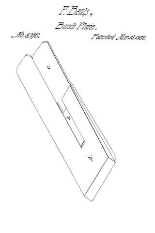
Be it known that I, Z. PHILLIPS, of Dixon, in the county of Lee and State of Illinois, have invented certain new and useful Improvements in Carpenters’ Planes; and I do hereby declare that the following is a full, clear, and exact description thereof, reference being had to the accompanying drawings, and to the letters of reference marked thereon, which form a part of this specification.

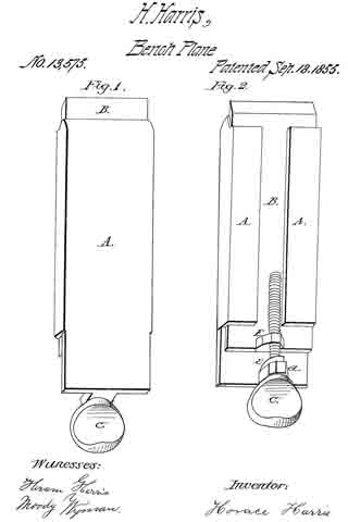
The nature of my invention consists, first, in so constructing a plane-iron that the bit can be raised and lowered at will by means of a thumb-nut without removing the hand from its natural position; and second, in so constructing a plane-iron that the bit can be tightened or loosened at will by means of a thumb-nut without removing the hand from its natural position.

In order to enable others skilled in the art to which my invention appertains to make and use the same, I will now proceed to describe its construction and operation, referring to the annexed drawings, in which —

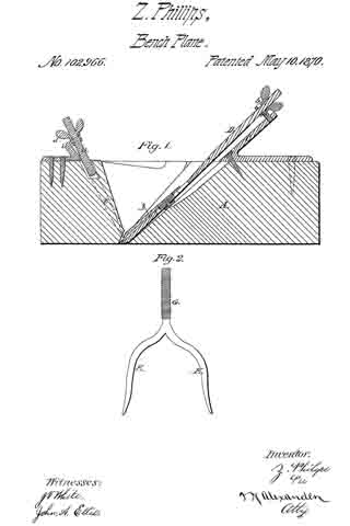
Figure 1 is a longitudinal vertical section of my planing-iron, and Fig. 2 is a front view of the fork which tightens the bit.

A represents the usual wood part or stock of a plane, having a V-shaped aperture for the insertion of the bit B. Immediately in rear of this aperture, on top of the stock A, is secured an inclined rest, C, provided with a forked projection, a, to hold the thumb-nut on the bit.

The bit B is provided at its upper end with a shank, D, having screw-threads, and a thumb-nut, b, placed on the same. The thumb-nut b is grooved, so as to pass into and be held by the forked projection a.

In small planes the rest C, with the nut D, may be used as a handle, but in larger planes the handle would be placed close to the said rest, so that the operator can, without removing his hand from the handle, turn the thumb-nut b in either direction, and consequently raise or lower the bit.

The bit B is tightened or loosened at will by the following means: A fork, E, provided with a screw-shank, G, is passed down through an inclined slot in the stock A in front of the aperture through which the bit is passed, the ends of the fork resting upon the bit, as shown in Fig. 1. On the screw-shank G is placed a thumb-nut, d, which is grooved and held in a forked rest, e, on the stock. By turning the thumb-nut d in one direction the fork E will be lowered, so as to bear against the bit and tighten the same, and by turning said nut in the opposite direction the fork is raised and the bit loosened, which all can be accomplished without the operator having to remove his left hand from the usual position on the plane.

Having thus fully described my invention, what I claim as new, and desire to secure by Letters Patent, is —

1. The fork E, when constructed and arranged to operate in the manner and for the purpose set forth.
2. In combination with the fork E, bit B, when constructed and arranged to operate as and for the purpose described.

In testimony that I claim the foregoing as my own I affix my signature in presence of two witnesses.

ZEPHANIAH PHILLIPS.

Witnesses:
GEO. CURKENDALL,
D. H. LAW.

No. 64,001 – Improvement In Plane Irons (William H. Eckert) (1867)

[paiddownloads id=”123″]64001


United States Patent Office.


WILLIAM H. ECKERT, OF SYRACUSE, NEW YORK.

Letters Patent No. 64,001, dated April 23, 1867.
_________________

IMPROVEMENT IN PLANE IRONS.

_________________

The Schedule referred to in these Letters Patent and making part of the same.

_________________

TO ALL WHOM IT MAY CONCERN:

Be it known that I, WILLIAM HENRY ECKERT, of the city of Syracuse, Onondaga county, New York, have invented a new and improved Plane; and I do hereby deciare that the following is a full, clear, and exact description of the same, reference being had to the annexed drawings, making a part of this specification.

The letters used represent corresponding parts wherever they occur.

To enable others skilled in the art to make and use my invention, I will proceed to describe the same, and its form when complete and ready for use.

Figure 1 represents a perspective view of the plane irons when put together.

Figure 2 represents the cap.

Figure 3 represents a cross sectional view of both the plane irons, with the nut and screw.

In the common form of plane irons the screw is made to pass directly into the cap, for the purpose of holding the two irons together. This form of construction involves the necessity of unscrewing the cap when-ever the irons are separated for sharpening, or any other purpose of separation. The object of my invention is to dispense with this necessity and enable the irons to separate by simple handling.

I make the cutting iron A in all respects in the common form, with an elongated slot, a, for the movement of the screw s, and with a circular aperture, o, for the screw-head to pass through. Instead of inserting the screw in the cap, I make the nut n, which may be in any convenient form, square, oblong, circular, or other-wise; but I consider the oblong form the best, because best calculated to bold the cap straight with the cutting iron. In the cap C I make the slot or opening h, into which the nut n is made to fit, and it should be so made as to receive the nut with a snug joint. By this means the cap C, which in other respects is made in the common form, is readily adjusted by means of the screw and the irons, separated by slipping the cap C off from the nut n.

What I claim as my invention, and desire to secure by Letters Patent, is —

The nut n, in combination with the planing iron A, the screw s, and the cap C, made and operated substantially as and for the purposes described.

I also claim the slot h in the cap C, when made to it upon the nut n, and applied to planing irons, substantially as described.

WM. H. ECKERT.

Witnesses:
N. B. SMITH,
G. W. SMITH.

No. 72,443 – Improvement In Carpenters’ Planes (Leonard Bailey) (1867)

[paiddownloads id=”134″]72443


United States Patent Office.


LEONARD BAILEY, OF BOSTON, MASSACHUSETTS.

Letters Patent No. 72,443, dated December 24, 1867.
_________________

IMPROVEMENT IN CARPENTERS’ PLANES.

_________________

The Schedule referred to in these Letters Patent and making part of the same.

_________________

TO ALL PERSONS TO WHOM THESE PRESENTS SHALL COME:

Be it known that I, LEONARD BAILEY, of Boston, in the county of Suffolk, and State of Massachusetts, have invented a new and useful Improvement in Bench-Planes; and I do hereby declare the same to be fully described in the following specihcation, and represented in the accompanying drawings, of which —

Figure 1 is a top view, and Figure 2, a longitudinal section of a plane-iron and its cap-iron, and their holding-devices, such cap-iron being constructed in accordance with my improvement.

Figure 3 is a longitudinal section of the plane-iron and cap-iron, as ordinarily constructed, that is to say, with one bend, a, only near the bearing-edge of the cap-iron.

My object is to use very thin steel plane-irons, and in so doing I find that they are liable to buckle under the pressure of the cap, which causes them to chatter, and makes them otherwise imperfect; and my invention consists in the providing of an auxiliary point of contact between the cap and plane-iron, and at the point where the plane-iron tends to buckle or rise from its bed or base, and thus have a pressure at that point in addition to that at the cutting-edge, which firmly holds this thin plane-iron to its bed.

The cap-iron, as commonly constructed, that is, as shown at D, in fig. 3, when applied to the plane-iron E, will rest thereon only at the extreme lower end of the cap-iron, and also at or very near its upper end. There will be along angular space, b, between the two irons, when they are clamped together by the holding-devices which are represented in figs. 2 and 3, at A, B, and C, and consist of a screw, A, a bearing, B, and a cam-lever, C, arranged in a manner well known.

The dfficulty experienced from the construction of the cap-iron with the single bend a, is, that it allows of vibration of the cap-iron and the plane-iron while in use, such vibration being productive of what joiners term “chattering,” and consequent defective operation of the plane.

In carrying out my improvement, I make the cap-iron with an additional bend, b, (see figs. 2 and 3,) at a short distance back of its lower end or toe, or at a distance therefrom equal to about double the distance at which such lower edge or toe is to be from the main bend a, or the toe of the bearer B, the same being as shown in figs. 2 and I, so as to cause the cap-iron D’ to bear on the plane-iron E’ in three places, or at the toe and auxiliary bend of the cap-iron, and along from such bend to the heel or upper end of the cap-iron. This construction or formation of the cap-iron D’ completely obviates the difficulty above mentioned, and is a very valuable and useful improvement.

In all bench~planes the plane-iron must project slightly beyond its bed or bearing, the edge of the bed beyond which it projects serving as a fulcrum to the force of the pressure ofthe cap upon the extreme edge of the plane-iron. When thick plane-irons are used, their stiffness may resist the pressure of the cap sufficiently to prevent buckling or rising of the plane-iron from its bed; but in thin steel plane-irons which I use, the pressure of the cap upon the projecting portion of the plane~iron causes this portion to yield slightly, and of course produces buckling at some point behind, and generally close to the fulcrum. To prevent this buckling or rising, and still use the thin steel plane-irons, I put an extra bend in the cap, so that it shall have a point of impact with the thin steel at the place where it tends, from the pressure on its projecting edge, and the fulcrum behind that edge, to risefrom its bed, and thus I effectually prevent “buckling” and “chattering,” whilst I can avail myself of the economy of thin steel for the plane-irons.

What I claim as my invention, and desire to secure by Letters Patent in the adaptation of thin steel to the plane-irons of bench-planes, is —

The auxiliary point of impact between the cap and the thin plane-iron, at the point or portion thereof where the thin steel tends to buckle under the pressure of the cap upon the projecting edge of the plane-iron, substantially in the manner described.

LEONARD BAILEY.

Witnesses:
R. H. EDDY,
F. P. HALE, Jr.

No. 67,458 – Improvement In Carpenters’ Planes (G.D. Spooner And L.N. Johnson) (1867)

[paiddownloads id=”131″]67458


United States Patent Office.


G. D. SPOONER, OF RUTLAND, AND L. N. JOHNSON, OF BRANDON, VERMONT

Letters Patent No. 67,458, dated August 6, 1867.
_________________

IMPROVEMENT IN CARPENTERS’ PLANES.

_________________

The Schedule referred to in these Letters Patent and making part of the same.

_________________

TO ALL WHOM IT MAY CONCERN:

Be it known that We, G. D. SPOONER, of Rutland, and L. N. JOHNSON, of Brandon, both in the county of Rutland, and in the State of Vermont, have invented a new and useful improvement in Planes; and we do hereby declare that the following is a full, clear, and exact description thereof, which will enable those skilled in the art to make and use the same, reference being had to the accompanying drawing, forming part of this specification, in which drawing —

Figure 1 represents a longitudinal vertical section of the invention.

Figure 2 is a sectional plan or top view of the same.

Similar letters of reference indicate corresponding parts.

This invention relates to a plane in which the bit or plane-iron is secured by means of a set-screw to a cross-head, which is adjustable by means of a thumb-screw in a slotted plate fastened to the stock of the plane, and which is provided with shoulders in such a manner that when the set-screw which forms the connection between the plane-iron and the cross-head is released, the cutting edge of the plane-iron can be readily adjusted in the required position by turning the thumb-screw, and by screwing up the set-screw the plane-iron is firmly retained in the required position.

A represents the stock of our plane, which is made of wood or any other suitable material. This stock is provided with a cavity to receive a metal plate, B, which is firmly secured to the stock, and the outer surface of which is in line with the inner surface of the throat of the plane, as clearly shown in fig. 1 of the drawing. The plate B is furnished with a slot, a, which forms the guide for the cross-head C, which is provided with lips, b, projecting over the inner edges of the slot a, as shown in fig. 2. When the cross-bead is in position in the slot it its outer surface or face is slightly below the outer surface ofthe plate B, and said cross-head is tapped to receive the set-screw c, which forms the connection between the plane-iron D and the cross-head. If the set-screw is screwed up it draws the cross-head up against the inner surface of the plate B, and at the same time it presses the plane-iron down tight against the outer surface of said plate and holds the same firmly in position. If the set-screw c is released the cross-head C can be moved up or down in the slot a by means of the thumb-screw E, the upper end of which is provided with a journal which has its bearing in a forked lug, d, projecting from the inner surface of the plate B, being retained therein by a pin, e, or in any other suitable manner, while the screw-shank of said thumb-screw is tapped into the cross-head, as shown in the drawing. If the set-screw c is released, therefore, the cutting-edge of the plane-iron can be readily adjusted in the desired position, and said plane-iron can also be turned so as to bring its cutting edge square with the sole of the plane, and after it has been so adjusted the set-screw is screwed up tight and the plane-iron is firmly retained in position. A cap, F, may be attached to the plane-iron by screws f which do not interfere with the motion of the plane-iron on the plate B. This arrangement is very simple, and it obviates all complicated and costly mechanism for retaining the plane-iron in position after the same has been adjusted in the required position by the action of the thumb-screw, no change in or attachment to the ordinary plane-iron being required in order to adapt it to our improvement.

We are aware of a plane described in Letters Patent of J. F. Palmer, February 3, 1857, which bears some resemblance to ours. He uses a thumb-screw like ours, but the nut of his thumb-screw is stationary, and in order to give motion to the plane-iron he attaches to the same a fork which catches in a neck of the thumb-screw; and furthermore, his plane-iron must be provided with a slot to admit the set-screw. ln our plane an ordinary plane-iron can be used, nothing being needed but a simple round hole to admit the set-screw, so that if the plane-iron is worn out it can be readily replaced.

What we claim as new, and desire to secure by Letters Patent, is —

The sliding cross-head C, provided with shoulders b, which bear against the inner surface of the plate B, said cross-head being made to receive the set-screw c and the thumb-screw E, which catches in a forked lug d, projecting from the inner surface of the fixed plate B, to operate in combination with the plane-iron D, as and for the purpose described.

G. D. SPOONER,
L. N. JOHNSON.

Witnesses:
W. G. VEAZEY,
E. J. HARTSHORN.

No. 19,359 – Securing The Plane Iron To Its Stock (P.A. Gladwin) (1858)

[paiddownloads id=”71″]19359


UNITED STATES PATENT OFFICE.

_________________

P. A. GLADWIN, OF BOSTON, MASSACHUSETTS.

METHOD OF SECURING THE PLANE-IRON TO ITS STOCK.

_________________

Specification of Letters Patent No. 19,359, dated February 16, 1858.

_________________

To all whom it may concern:

Be it known that I, P. A. GLADWIN, of Boston, in the county of Suffolk and State of Massachusetts, have invented a new and useful Improvement in Joiners’ Planes; and I do hereby declare that the following is a full, clear, and exact description of the same, reference being had to the annexed drawings, making a part of this specification, in which —

Figure 1, is a longitudinal vertical and central section of my iinproveinent. Fig. 2, is a transverse section of do, taken in the line (x), (x), Fig. 1, and looking in the direction indicated by the arrow. Fig. 3, is a plan or top view of do.

Similar letters of reference indicate corresponding parts in the several figures.

This invention consists in a novel manner of securing the iron in the plane, as hereinafter described, whereby the iron may be readily adjusted in the plane and at the same time firmly secured therein.

To enable those skilled in the art to fully understand and construct my invention I will proceed to describe it.

A, represents the stock of a plane constructed externally in the usual way and provided with an ordinary cutter or “iron” B.

C, is the “throat” of the plane in which the iron B, is placed or fitted and secured. This throat is not provided with the usual grooves at its sides (a) to receive a wooden wedge as ordinary planes, the sides of the throat being perfectly vertical and the space between the sides being equal to the width of the iron B, as shown clearly in Fig. 2. The back (b) of the throat C, has the usual inclination, and its front is of double inclined form as usual and shown at (c) (d) Fig. 1. On the inclined part (c) of the front of the throat C, a plate D, is placed. This plate has an oval opening (e) made in it as shown clearly in Fig. 2, and the lower edge of the plate has a foot piece or projection (f) at each end, the lower surfaces of which are parallel with the outer surface of the cover or cap E, of the iron, see Fig. 1.

F, is a plate on the inner side of which a projecting ledge or bit (g) is formed. This plate is secured to the part (c) of the front side of the throat by a screw (d’) which passes through the oval opening (e) in the plate D, the plate being allowed to turn on said screw and the ledge or bit (g) also fits within this opening as shown clearly in Figs. 1 and 2. The ledge or bit (g) is not at the center of the plate F, but is rather at one side of it, the screw (d’) passing through one end of the ledge or bit (g) as shown clearly in Fig. 2. The plate F, is provided with a thumb piece (h) at its upper end.

In consequence of having the bit (g) placed at one side of the center or screw (d’) and having said bit fitted within the oval opening (e) of the plate D, the plate D, will be raised and lowered turning the plate F, on its screw or center (d and it will be seen that when the plate F, is turned in the direction indicated by arrow (1) the foot pieces or projections (f), (f), will be forced down or against the cap or cover E, of the iron B, and will retain the iron firmly in its place as shown in black in Fig. 1, and in red in Fig. 2. By turning the plate in the opposite direction as indicated by arrow (2) the foot pieces or projections (f), (f) will be raised and the iron may be entirely withdrawn from the stock or adjusted or set as desired and then firmly secured by turning plate F, in the direction indicated by arrow 1.

This invention is extremely simple and allows of the ready adjustment of the iron.
It may be applied to any ordinary plane with the greatest facility, the device being made of varying sizes to suit different sized planes.

Having thus described my invention what I claim as new and desire to secure by Letters Patent, is,

The two plates D, F, constructed as shown, viz., the plate D, being provided with the foot pieces or projections (f), (f), and the oval opening (e), and the plate F, provided with the bit (g) and pivoted to the part (c) of the throat C, so that the bit may work within the oval opening (e) of the plate D, substantially as and for the purpose set forth.

P. A. GLADWIN.

Witnesses:
SAMUEL CALDIROTT,
J. B. CALDIROTT.

No. 20,615 – Device For Adjusting Plane Irons (Leonard Bailey) (1858)

[paiddownloads id=”76″]20615


UNITED STATES PATENT OFFICE.

_________________

L. BAILEY, OF WINCHESTER, MASSACHUSETTS.

DEVICE FOR ADJUSTING- PLANE-IRONS.

_________________

Specification of Letters Patent No. 20,615, dated June 22, 1858.

_________________

To all whom it may concern:

Be it known that I, LEONARD BAILEY, of Winchester, in the county of Middlesex and State of Massachusetts, have invented a new and useful Improvement in Joiners’ Planes; and I do hereby declare that the same is fully described and represented in the following specification and the accompanying drawings, of which —

Figure 1, is a top view. Fig. 2, a side elevation; and Fig. 3, a vertical, central and longitudinal section of a plane having my improvement. Fig. 4, is a top view of the friction plate and its adjuster.

The nature of my invention consists in the application of a movable friction plate and a device for adjusting or moving it to the rear side of the throat of a plane stock, and so as to support the plane iron or cutter and be a means by which it may be set or adjusted with respect to the bearing or bottom of the plane stock.

In the drawings, A, denotes the stock of which B, is the throat; C, the plane iron, the latter with its cap iron D, being held in place by a lever E, a thumb cam F, and a bearer or screw, G.

The bearer extends upward from the rear side of the throat and through slots made in the plane iron, the cap iron and the lever and its head serves as a fulcrum to the lever. A spring, H, projecting from the lever as shown in the drawings, serves to separate the thumb cam from the cap in a manner to prevent the former from being turned by the latter while it is being moved longitudinally with the plane iron.

I, is a metallic plate, which is placed fiat against the rear face a, of the throat, B, and serves to support the plane iron. This plate I, is formed with a slot, b, and a circular opening, c, the latter being for the reception of an eccentric, d, projecting from a lever, e, which turns on a fulcrum or screw, f, arranged as shown in the drawings. By turning the lever on its fulcrum in one direction the friction plate, will be raised upward in the throat. So by turning the lever in the opposite way, the plate will be depressed, the amount of movement of the friction plate depending on that of the lever. As the plane iron or cutter rests directly on and is forced down upon the friction plate, it will be moved by and with the latter and so that its cutting edge may be adjusted with great nicety with respect to its distance from or beyond the supporting face or bottom surface of the stock.

The lever, e, the eccentric, d, and the opening c, I term the adjuster, as when applied to the stock and plate, I, as described, they constitute a means of adjusting the plane iron as explained. Were the adjuster applied directly to the plane iron as it is to the friction plate, that is were we to dispense with the friction plate and insert the eccentric of the adjuster in a circular orifice made in the plane iron, it will be readily seen that but very little wear of the plane iron, such as must necessarily take place in sharpening it, or in other words, a reduction of its length, a distance equal to the eccentricity of the eccentric, would render the iron useless. By having a friction plate independent of the plane iron, the extent of grinding or reduction of the plane iron is not limited to the amount of eccentricity of the eccentric, but may be carried on to a much greater extent. Thus, the advantages of my invention will be apparent. It can be applied to most ordinary plane stocks without alteration of the plane iron, or any addition thereto, and it enables the plane iron to be adjusted with great nicety, without requiring the fastening contrivance to be first loosened.

I claim —

The combination of the movable friction plate, I, (separate from the plane iron, C,) and its adjuster or the equivalent of the latter with the throat of the plane stock and to operate the plane iron substantially as specified.
In testimony whereof, I have hereunto set my signature.

LEONARD BAILEY.

Witnesses:
R. N. EDDY,
F. P. HALE, Jr.

No. 21,311 – Securing Plane Irons To The Stocks Of Bench Planes (Leonard Bailey) (1858)

[paiddownloads id=”79″]21311


UNITED STATES PATENT OFFICE.

_________________

LEONARD BAILEY, OF WINCHESTER, MASSACHUSETTS.

METHOD OF SECURING PLANE-IRONS TO THE STOCKS OF BENCH-PLANES.

_________________

Specification of Letters Patent No. 20,311, dated August 31, 1858.

_________________

To all whom it may concern:

Be it known that I, LEONARD BAILEY, of Winchester, in the county of Middlesex and State of Massachusetts, have invented a new and useful Improvement in Hand-Planes; and I do hereby declare that the same is fully described and represented in the following speciiication and the accompanying drawings, of which —

Figure 1 denotes a top view of a smoothing plane having my invention applied to it; Fig. 2, a side elevation of it, while Fig. 3 is a central, vertical and longitudinal section of it. Fig. 4 is an underside view of the plane iron and its cap, Fig. 5 being a top view of the same. Fig. 6 is a view of the clamp lever and thumb cam thereof to be hereinafter described.

The object of my invention is to provide the plane with a ready means of fixing the plane iron or cutter in the stock or of removing the same therefrom as well as of adjusting the plane iron in the stock as circumstances may require.

In the drawings, A, exhibits the plane stock furnished with a throat, B, for the reception of the cutter or plane-iron, C, or the same and its cap iron, D. In the above mentioned drawings the cap iron, D, is exhibited as confined to the plane iron or cutter, C, by means of a screw h, extending upward from the underside of the cutter C, and through a long slot, b, formed in the said cutter as shown in Figs. 3 and 4. The bearing surface of the throat or that marked d, d, in Fig. 3, is furnished with a recess, e, for the reception of the head of the screw, h, by which the cap iron is confined to the plane iron, such recess being made of a sufficient size or diameter to allow the necessary longitudinal movements of the plane iron. Furthermore, the cap-iron as shown in the drawing, is made with a hole, f, arranged midway between its two edges and directly over the slot in the plane iron, such hole being to enable the plane iron and its cap to be passed over the head of a bearer or screw F, inserted in the plane stock and made to project from the bearing surface d, d, as shown in Fig. 3. In connection with this screw or bearer, F, a clamp lever or plate, G, is employed, it being formed as represented in the drawings and hinged or jointed at its upper end to a thumb cam, H. Moreover, the clamp lever, G, has an elongated slot, s, made through it, the said slot in one half its length being circular in form and having a diameter or width somewhat larger than the head of the bearer or screw, F, while the remainder of the slot is constructed of a width or diameter less than that of the head of the screw and sufficient to receive the shank of the screw the whole being as shown in the drawings. In consequence of the slot being so made we are enabled to slip or pass the clamp lever, G, over the head of the screw and to press the said clamp lever, G, downward in such manner as to cause the head of the bearer or screw to project beyond the sides of the slot, and constitute a fulcrum for the clamp plate when the thumb cam is turned down into the position as shown in Figs. 1 and 2. By turning the thumb cam down, we clamp or confine the plane iron in the stock, but by turning such thumb cam upward so as to bring it into the position as represented in Fig. 7 (which is another longitudinal section of the plane) we loosen the clamp lever from the bearer in such manner as to enable us either to remove it therefrom or to adjust the plane iron as circumstances may require. By turning backward the thumb cam, it will be made to so operate against the plane iron or the cap thereon as to raise the upper end of the clamp lever and force the lower end against the bearer in such manner as to cause the lower end of the clamp plate to be pressed downward upon the plane iron and secure such iron firmly upon its bearing surface, d, d. Thus it will be seen that by means of the bearer, the clamp lever and the thumb cam the plane iron may be secured in place in the throat of the plane stock or released therefrom with great facility or expedition.

By making the shank of the bearer to screw into the stock we cause the bearer to be adjustable with reference to the seat of the plane iron, and therefore we have a means of readily adapting the bearer to a plane iron of any ordinary thickness, whether provided or not with a cap iron, the adjustment of the bearer being for the purpose of causing the thumb cam and the clamp lever to be brought into the proper situations to enable them by their conjoint action as described to fasten the plane iron to the stock. If desirable, there may be two bearers, F, but I prefer to have but one, as such is quite suflicient. These bearers may be arranged near the edges and may project either from or into the stock. A single bearer, however, arranged in the middle of the seat of the plane iron and either made stationary or adjustable with respect to such seat is far preferable to more than one. Furthermore by the employment of one bearer and its arrangement at the middle of the plane iron and the clamp lever as described the lower bearing edge of the clamp lever is left free to perfectly or so perfectly adjust itself to the plane iron or the cap iron thereof as to bear thereon throughout the entire length of the edge.

I claim —

The application and arrangement of one or more bearers, F, the clamp lever, G, and the thumb cam, H, together and with respect to the top surface of the plane iron and the bearing surface or cutter seat, d, d, of the throat substantially as represented and described.

LEONARD BAILEY.

Witnesses:
R. H. EDDY,
F. P. HALE, Jr.

No. 24,335 – Securing The Bits Of Bench Planes (Charles W. Seely And Benjamin F. Locke) (1859)

[paiddownloads id=”84″]24335


UNITED STATES PATENT OFFICE.

_________________

CHAS. W. SEELY AND BENJ. F. LOCKE, OF WELLINGTON, OHIO.

MANNER OF SECURING THE BITS OF BENCH-PLANES.

_________________

Specification of Letters Patent No. 24,335, dated June 7, 1859.

_________________

To all whom it may concern:

Be it known that we, CHARLES W. SEELY and BENJAMIN F. LOCKE, of Wellington, in the county of Lorain and State of Ohio, have invented a new and Improved Plane-Bit for Planing Wood, and we do hereby declare that the following is a full and exact description thereof, reference being had to the accompanying drawings and the letters of reference marked thereon.

The nature of the invention consists in adjusting a steel bit between a cap and bed piece, which cap and bed piece are similar to the common cap and plane bit now generally used, and usually designated as the double plane bit. Our bit is manufactured entirely of steel and therefore we avoid the injurious effect produced upon steel, by the great heat to which it is necessary to subject it, to weld it upon iron; and thus we obtain a much finer and keener edged implement than can be obtained from the common method of manufacturing plane bits. Our bit also requires much less grinding than the common bit, and can be manufactured at less expense.

To enable others skilled in the art to make and use our invention, we proceed to describe its construction and operation.

This bit is manufactured of steel only, and is a thin plate varying from a sixteenth to an eighth of an inch in thickness, or thereabout, and of the usual width, with a notch in the middle of the upper end for the passage of the fastening screw. Each opposite corner of the notched end of the bit is turned down to form spurs to mesh into grooves or notches, in the bed piece, which see Figure “2” in the diagram letters “a a” which represent the steel bit and the corners.

The bed piece is represented by Fig. “1” of the diagram, is made of iron of the same width of the steel bit, and of the length of the common plane bit. The notches or grooves “a a” are for the spurs on the steel bit to mesh into, and are made about one-fourth the width of the bed piece from each edge thereof, and are exactly parallel. These and the spurs on the steel bit, are to prevent the bit from slipping up when force is applied for planing. The circular hole and notch in the bed piece is the same as in common use, and is for the entrance of the screw, by which the three pieces are fastened together as seen in Fig. “4”

The cap is made in the same manner, and like the common cap now in use, with the exception of a bar of iron just above the screw hole, and to be of the thickness of the steel bit, which is welded or riveted on the inner surface of the cap. This cross piece or bar is to prevent the cap from pressing upon the upper end of the steel bit, and thus prying apart the lower ends when the three are joined by the screw; instead of this cross piece or bar any means of making an elevation on the same surface of the cap may be used. This cap with the cross piece or bar is represented in Fig. “3” letter “a” and is also seen in Fig. “4” letter “c” The mashing of the spurs on the steel bit into the grooves on the bed piece is seen at “a” Fig. “4.”

We do not not claim broadly the interposition of a steel planing bit between a cap and bed piece, as this already has been done, but

What we claim, is —

Stopping the upper end of the interposed bit below the screw, and upsetting it, so as to catch into the cross serrations in the bed piece, as set forth.

CHARLES W. SEELY.
BENJAMIN F. LOCKE.

Witnesses:
JONATHAN ARNATT,
J. L. HUTCHINSON.

No. 30,248 – Device For Securing Plane Bits (Theodore M. Richardson) (1860)

[paiddownloads id=”90″]30248


UNITED STATES PATENT OFFICE.

_________________

T. M. RICHARDSON, OF STOCKTON, MAINE.

DEVICE FOR SECURING PLANE-BITS.

_________________

Specification of Letters Patent No. 30,248, dated October 2, 1860.

_________________

To all whom it may concern:

Be it known that I, THEODORE M. RICHARDSON, of Stockton, in the county of Waldo and State of Maine, have invented an Improved Joiner’s Plane; and I do hereby declare that the same is fully described in the following specification and represented in the accompanying drawings, of which —

Figure 1, is a top view; Fig. 2, a side view; Fig. 3, a longitudinal section, and Fig. 4, an underside view of it. Fig. 5, exhibits a transverse section taken through the middle of the slider arranged in the side of the plane stock.

In these drawings A, denotes the stock, and, B, the handle thereof, the two being formed of metal or other suitable material and secured together by screws, a, a. The throat, b, of the plane stock is furnished with a stationary cap iron or cutter bearing, C, against the underside of which the cutter or plane iron, D, is arranged as shown in the drawings. The said plane iron is forced or clamped against the cap iron, C, by means of a wedge, E, a pitman, F, an inclined plane G, and a screw H, arranged relatively to each, the plane stock, the cutter and handle as shown in the drawings, that is to say, the wedge, E, is placed between the cutter and the base plate of the stock, while the inclined plane, G, is disposed in front of the handle and the pitman is made to extend from the inclined plane to the wedge and has the screw, H, carried through it and screwed into the front part of the base of the handle. By screwing down the said screw, the pitman will be forced down the inclined plane and by the latter will be driven forward against the wedge and thereby cause the said wedge to force the cutter or plane iron hard up against the bearing or cap iron, C. A slider, I, is arranged in the side of the plane stock and so as to slide into the recess, K, formed therein, and parallel or nearly so to the cutter. When the said slider is made to extend out of the socket or recess and beyond the lower face of the plane stock as shown in the drawings, it will serve as a guide for a workman in planing a “glue joint” or one surface at right angles to another the slider serving, in this respect, the purpose of an ordinary carpenter’s square, as its inner face, when the slider is extended shall stand at ip right angle with the underside of the stock.

In rear of the handle and in its base, I arrange a small glass spirit level L, and so as to stand transversely with respect to the plane stock, in other words at right angles with its sides, the said level being disposed as shown in Figs. 1 and 3. By this arrangement of the level it is covered and protected by the wrist of a workman while his hand may be grasping the handle, B, and thus the level is not so likely to becoine broken as would be the case were it arranged at the opposite end of the stock and in advance of the handle. My arrangement of the parts for holding the plane iron in place enables such iron to be removed and replaced with respect to the cap iron without requiring the aid of a screw driver or hammer.

I claim —

The arrangement of the clamp wedge E, the pitman, F, the inclined plane, G, and the screw, H, with the plane iron D, its cap bearing, C, and the stock A, substantially as described.

T. M. RICHARDSON.

Wtitnesses:
HENRY S. STAPLES,
ALEXANDER STAPLES, Jr.

No. 16,309 – Adjusting Bits Of Carpenter’s Planes (Thomas D. Worrall) (1856)

[paiddownloads id=”34″]16309


UNITED STATES PATENT OFFICE.

_________________

THOMAS D. WORRALL, OF LOWELL, MASSACHUSETTS.

ADJUSTING THE BITS OF CARPENTERS’ PLANES.

_________________

Specification of Letters Patent No. 16,309, dated December 23, 1856.

_________________

To all whom it may concern:

Be it known that I, THOMAS D. WORRALL, of Lowell, in the county of Middlesex and State of Massachusetts, have invented certain new and useful Improvements in Carpenters’ Bench-Planes; and I do hereby declare that the same is fully described and represented in the following specification and the accompanying drawings, of which —

Figure 1, is a top view. Fig. 9, a side elevation. Fig. 3, a vertical and longitudinal section, and Fig. 4, a horizontal and longitudinal section of one of my improved bench planes, the latter section being taken through the pinion gear by which the plane-iron or cutter may be elevated or depressed within the throat of the stock.

In the said drawings, A, denotes the stock, B, the cutter or plane-iron, and, C, the throat of the stock.

In order to hold the plane-iron within the stock, I employ a clamp or piece of metal, D, made so as to embrace a dovetailed rack bar E, fixed to the rear side of the cutter, B, as shown in Figs. 3 and 4. The clamp is arranged within a cavity or recess, F, formed in the stock and leading out of the rear side of the throat thereof. A female screw, a, is made through the rear part of the clamp and so as to receive a male screw cut on the end of a long rod, G, which extends backward through the stock and has a hexagonal head, c, as shown in the drawings. The rack, E, is provided with teeth on its rear side to cooperate with a pinion, H, arranged and made to turn within the clamp, and to have its shaft, I, extended laterally through the plane stock and formed so as to receive a key, by which it and the pinion may be put in rotation for the purpose of regulating the distance of the cutting edge of the plane-iron relatively to the lower surface of the stock. Such distance having been obtained, the clamp, D, is to be brought into action or to be drawn backward so as to act upon the dovetail of the rack and so as to draw the plane-iron firmly against the rear face or side of the throat and hold said plane-iron in its proper place.

From the above it will be seen that we not only have a means of clamping the plane-iron, but of readily adjusting it in the stock. Furthermore a cap iron, K, is applied to the plane iron for the purpose of enabling it to plane cross grained stud, a top view of said cap and the plane-iron being represented in Fig. 5. Instead of making this cap straight from end to end, or with its under surface a plane surface, as it is usually made, I give to it a curved form throughout its entire length as shown in Fig. 3, and provide the cap with a slot, L, arranged in it as shown in the drawings. A clamp screw, M, extends through the slot and into the plane-iron, the same being for the purpose of confining the cap to the plane-iron. In order to regulate the longitudinal movement of the cap iron, or plane-iron I apply to the cap and plane-iron an adjusting screw, as shown at N. Thus it will be seen that the plane stock is not employed as a bearing for the device by which the cap is held to the plane-iron, such device being entirely independent of the stock.

By making the cap curved in manner as described its lower end may be forced down into perfect contact with the upper surface of the plane-iron, and will not spring there from so as to admit shavings or pieces of wood between it and the cutting edge of the plane while it is in use. It is well known that when the cap is made perfectly flat it is liable to be raised off the iron by slivers or chips which may become wedged between their lower ends, the same serving to interrupt the proper action of the cap. By making the cap in my improved manner and by applying a clamp to it so as to be independent cf the stock in the way above described, I am not only able to effect the proper fixation of the cap iron, but can adjust the plane iron or move it up and down without disturbing the said adjustment of the cap thereon.

I claim —

The arrangement of the rack and pinion and the clamp so that while the pinion is placed within the clamp, the rear or dove-tailed sides of the rack bar shall serve as bearings for the clamp to work against.
In testimony whereof I have hereunto set my signature this eighteenth day of September, 1856.

THOMAS. D. WORRALL.

Witnesses:
R. H. EDDY,
F. P. HALE, Jr.

No. 14,979 – Method Of Securing Plane Bits (Thomas D. Worrall) (1856)

[paiddownloads id=”33″]13957


UNITED STATES PATENT OFFICE.

_________________

THOMAS D. WORRALL, OF BOSTON, MASSACHUSETTS.

METHOD OF SECURING PLANE-BITS.

_________________

Specification of Letters Patent No. 14,979, dated May 27, 1856.

_________________

To all whom it may concern:

Be it known that I, THOMAS D. WORRALL, of Boston, in the county of Suffolk, and State of Massachusetts, have invented an Improvemnt in Carpenters’ Molding-Planes; and I do hereby declare that the same is fully described and represented in the following specification and the accompanying drawings, of which —

Figure 1, is a top view, and Fig. 2, a side elevation of a plane containing my improvement. Fig. 3, a vertical, central and longitudinal section of it. Fig. 4, a side view of the clamp to be hereinafter described. Fig. 5, a front view of said clamp. Fig. 6, a front view of the plane iron as removed from its stock.

The nature of my invention consists in an improved arrangement of clamping mechanism, or that used for retaining the plane-iron within the throat of its stock. In the said drawings A, denotes the stock; B, the cutter or plane-iron; and C, the throat of the stock.

In order to hold the plane iron within the stock, I employ a clamp or piece of metal, D, made to extend partially around it or embrace it and to be arranged with respect to it as seen in the drawings, the said clamp being placed in a recess a, leading out of the rear and upper part of the throat and made of a suitable size to allow the clamp to be moved backward far enough to draw the plane iron closely against the surface of the throat. A female screw, b, is formed through the rear part of the clamp and so as to receive a male screw, C’, out on the end of a long rod E, which extends longitudinally through the stock A and from its rear end to the clamp and has a shoulder, d, and a flat head or handle, e, as seen in the drawings. By turning the rod so as to cause the screw, C’, to enter the clamp, the said clamp may be drawn down closely upon the plane-iron so as to confine it closely or firmly in the throat of the stock.

By my arrangement of the confining contrivances, the throat of the plane-iron is not obstructed by any device, extending across it transversely, the plane cutter being held in place by the backward draft of the clamp and the bearing of the rod of the shoulder E, against the rear end of the plane stock.

I do not claim merely holding the plane or cutter in place in its throat by a wedge, screw, or equivalent device forced into the throat and across it and against the plane-iron, but

What I do claim is —

The arrangement of the clamp, D, and the screw rod E with respect to the plane cutter and its stock substantially as described.

In testimony whereof, I have hereunto set my signature this twenty-seventh day of February A. D. 1856.

THOS. D. WORRALL

Witnesses:
R. H. EDDY,
F. P. HALE, Jr.

No. 13,745 – Bench Plane Iron (J. Henry A. Bleckmann) (1855)

[paiddownloads id=”26″]13745


UNITED STATES PATENT OFFICE.

_________________

J. H. A. BLECKMANN, OF RONSDORF, NEAR ELBERFELD, PRUSSIA.

BENCH-PLANE IRON.

_________________

Specification of Letters Patent No. 13,745, dated November 6, 1855.

_________________

To all whom it may concern:

Be it known that I, J. HENRY A. BLECKMANN, of Ronsdorf, near Elberfeld, in the Kingdom of Prussia, have invented a new and Improved Plane-Iron; and I do hereby declare that the following is a full and exact description thereof.

The nature of my invention consists in forming a plane-iron by placing between iron plates in the shape of the common double plane-irons a steel plate which may be advanced or drawn back by means of screws or a set screw.

The advantages arising from this my invention are, first, that I can employ well tempered steel plates which have not been injured by the process of welding it to another plate as it is done in the manufacture of common single or double plane iron; second, that I can easily change the cutting iron when necessary for another plate of the same temper and cutting quality; third, that it is cheaper than common plane iron now in use.

In the annexed drawings, Figure Ia represents a front view of my plane-iron. Fig.
Ib represents a back view of the same. Fig.
Ic represents a side view of the same; Figs.
IIa, IIb, IIc, front, back and side view of a modification; Fig. Id, side view of the same modihcation, taken without the top plate A;
Fig. III another modification.

My improved plane iron consists of two iron plates, A and B, between which a cutting iron, E F G H is placed. In order to keep the cutting iron firm between the front and back plates, I provide them with mortises M M (as seen in Figs. Ia, Ib, Ic) in which I insert screws J J, having nuts L L, by means of which I regulate the cutting iron E F G H. To keep the front and back plates A and B more firm together I provide them with another set of screws C C. When it is required to advance the cutting iron, I unscrew the nuts L L on the back-plate B, and push them and the cutting iron forward as far as necessary, and when the cutting iron has been placed in the desired position, I tighten the screws J J.

Here is another modification of my improved plane iron, (Figs. IIa,IIb, IIc). Instead of regulating the cutting iron by means of mortises and screws as described, I provide the cutting iron with a set screw K, by means of which the cutting iron may be advanced or drawn back at pleasure. For that purpose I construct differently the front and back plates A and B. The front plate A has a mortise M; in this mortise fits a set or regulating screw K, the lower portion of which is provided with a screw thread J J J J ; this regulating screw is kept in place by two pieces L and V, both fastened in the back plate, it works also in a nut R, which fits into the mortise of the cutting iron. The foot of this screw turns and is held in a socket S. When the screw K is turned, the nut R is either carried up or down and consequently the plane iron with it. To give the nut R more steadiness I make it so as to project beyond the mortise of the back-plate B. The back and front plates are kept together by means of four screws C C C C.

To prevent the shavings and dust from entering between the cutting iron E F G H and the top plate A, it is best to make said top plate somewhat curved at the point where it touches the cutting iron.

It is evident that a great many other modifications can be employed to arrive at the same object as I have shown in Fig. III, without departing from the principle of my invention.

What I claim as my invention and desire to secure by Letters Patent is —

The placing of a piece or a plate of steel between plates of iron, forming a plane iron for the purpose and in the manner above described.

J. H. A. BLECKMANN.

Witnesses:
FR. AUG. BUSCHE,
FRIEDR. WILH. ORTMANÜL

No. 13,575 – Plane Bit (Horace Harris) (1855)

[paiddownloads id=”25″]13575


UNITED STATES PATENT OFFICE.

_________________

HORACE HARRIS, OF GORHAM, NEW YORK.

PLANE-BIT.

_________________

Specification of Letters Patent No. 13,575, dated September 18, 1855.

_________________

To all whom it may concern:

Be it known that I, HORACE HARRIS, of Gorham, in the county of Ontario and State of New York, have invented a new and Improved Mode of Adjusting Bench-Plane Irons; and I do hereby declare that the following is a full and exact description thereof, reference being had to the accompanying drawings, making part of this specification, in which —

Figure 1 is a front view and Fig. 2 is a back view of the implement. I give the description “front” and “back view,” etc., from the position of the iron when in a plane stock. The “iron” embraces all the members found in the drawings.

In Fig. 1, A, B, C, are the same parts that are represented by them respectively in Fig. 2, except that in Fig. 1 A, is an iron used in the place of a cap in double irons for planes in common use, and in Fig. 2, A, A, are the side edges of said cap turned over on the back side of said iron to form grooves in which the bit B, (which is the part of the iron which cuts) is designed to be moved up or down for the purpose of cutting a coarse or line shaving. The grooves may be governed by turning the edges of the cap over the whole length, or only parts of the distance.

C, is a thumb screw at the top of the iron which is made to turn, without a screw thread in a back projection A, from the top of the cap, and is held from moving endwise by the head of the screw on the upper side, and by a nut E, pin, or otherwise on the lower side of said projection. The lower end of the screw is made to pass into a nut F, formed in a corresponding projection from the top of the bit. Thus the bit being nicely adjusted in the grooves is kept trim and steady while it is raised or lowered by the screw; and the screw thus arranged in the cap, (which is fast in the stock by a wedge, as are the irons in common planes), and at the same time connecting with the bit, helps to hold that firm to its place while it is in use. The advantages of this plan of adjustment are, that, 1st, it holds the bit more firmly and keeps it truer in its action than any other preceding screw adjustment, and, 2d, it is adapted to the ordinary wedge fastening arrangement in common bench planes, so that it can be readily used without any change of the common plane stock, thus giving it a general adaptation, with but little additional expense, that is, only the expense of the iron.

What I claim as my invention, and desire to secure by Letters Patent of the United States, is —

The adjustment of the cap and bit with the grooves at each side, and of the thumb screw at the top of the cap and bit, for the regulation cf the cut of the bit while the iron is held fast in the stock by the wedge fastening.

I am aware L. K. Wilman has an invention for fixing a plane iron in grooves in the sides of a plane stock, and of regulating the out of it with a screw at the top of the iron and turning in a nut in the stock; but my devices differ essentially from his in these points, viz., 1, that my grooves are in the plane iron itself, and therefore, for use, requires no changes of the stock or wedge, but with the wedge the iron is held firmer than by any arrangement without it; and 2 that my screw is attached to the cap and bit as the plane for working the bit in the grooves made fast in the stock by the wedge.

HORACE HARRIS.

Witnesses:

CHAS. E. UPPERMAN,
J. L. ADAMS.

No. 10,748 – Bit Fastening For Cast Iron Bench Planes (William S. Loughborough) (1854)

[paiddownloads id=”12″]10748


UNITED STATES PATENT OFFICE.

_________________

WM. S. LOUGHBOROUGH, OF VICTOR, NEW YORK

BIT-FASTENING FOR CAST-IRON BENCH-PLANES.

_________________

Specification of Letters Patent No. 10,748, dated April 4, 1854.

_________________

To all whom it may concern:

Be it known that I, WM. S. LOUGHBOROUGH, of Victor, in the county of Ontario and State of New York, have invented a new and useful Improvement in Cast-Iron Bench-Planes; and I do hereby declare that the following is a full, clear, and exact description thereof, reference being had to the accompanying drawings and to the letters of reference marked thereon.

Figure 1, is a side perspective. Fig. 2, is a perpendicular horizontal section, in which is represented the combination of the various parts. Fig. 3, is a plan of the adjustable, lever-cap l, showing the points e that form its fulcrum. Fig. 4, is a transverse section of the plane, through the handle h, showing the dovetail groove g, for the handle. Fig. 5, is a section of a part of one side, from within, showing the groove c, in which the fulcrum e, of the adjustable lever-cap l operates.

The nature of my invention, consists in the simplicity, convenience and perfection of its construction and operation. I prefer that form, for the body or stock of the plane, represented in the drawings, marked A–A, as it affords suficient strength in a very light article, when such is required.

s, seen in Figs. 1, 2, and 5, is the stem through which the screw d, — (seen in Figs. 1-2,) — works, and as it forms a part of the body, or stock of the plane, — being cast with it, it requires no fitting or adjusting thereto, as is the fact with that part of M. Chardoillet’s planes, and the lever, cap, and bit in his, being connected with this stem, directly, and the whole made to swing on a pivot that unites them with the stock, — the combination is much more complicated in that respect, than mine, besides, I avoid the necessity of a cap as a distinct and separate part, by using the lower end of the adjustable lever-cap, l, as a cap, when a double iron is required, thereby producing two desirable results, with one device.

Said device, (lever-cap l,) is operated, or adjusted by the screw f, operating upon the upper end of the bit, b, — its lower end, (marked v, in Fig. 3,) resting on the bit near its edge, and the fuicrum, e e, (in Fig. 3,) connecting with the stock in the grooves c c, one of which is shown in Fig. 5. This also fastens the bit. These grooves, (c c,) may be molded in the pattern, or may be cut by a ciicular file attached to the mandrel of a lathe.

To regulate the plane to plane veneers, and cross-grained lumber, &c., it is necessary to close the throat, 25, (in Figs. 2 and 5,) so as to prevent a thick shaving from raising, which would be the result, with the throat open, though you might have the cap of the double iron perfectly adjusted. The lever-cap l, may be raised at such times, — (as it is not needed as a cap,) and thus permit the shaving, however thin and weak to pass tlgrough entirely unobstructed, and without clogging.

All that is necessary to be done, to remove the bit b, is to give the screw f, a slight turn to the left, and the bit is loosened, and vice versa.

There are various ways of attaching the handle, h, to the stock. That represented in Fig. 4, is probably the best, being simply to mold in the pattern a dove-tail groove, g, to which the handle may be fitted and driven in.

What I claim as my invention and improvement, and desire to secure by Letters Patent is —

1. The combination of the adjustable lever-cap, l, with the screw, f, by which it is operated.

2. The manner of connecting the said adjustable lever-cap l, with the stock of the plane, as described, and for the purposes set forth.

WM. S. LOUGHBOROUGH.

Witnesses:
WM. M. FERGUSON,
S. C. FERGUSON.

No. 8,796 – Double Plane Iron (Fordyce Beals) (1852)

[paiddownloads id=”10″]8796


UNITED STATES PATENT OFFICE.

_________________

FORDYCE BEALS, OF PITTSFIELD, MASSACHUSETTS.

DOUBLE-PLANE IRON.

_________________

Specification of Letters Patent No. 8,796, dated March 16, 1852.

_________________

To all whom it may concern:

Be it known that I, FORDYCE BEALS, of Pittsfield, in the county of Berkshire, in the State of Massachusetts, have invented new and useful Improvements in Double-Plane Irons; and I do hereby declare that the following is a full, clear, and exact description of the construction and operation thereof, reference being had to the accompanying drawings, and to the letters of reference thereon, it being a part of this specification, in which —

A is the iron, C a section of the cap, and B a dovetail slide or projection of cap.

The nature of my invention consists in an improved arrangement for connecting and adjusting the cap to the iron.

To enable others skilled in the art to make and use my invention I will proceed to describe its construction and operation.

I construct my plane irons of any desired width, thickness, or form, with the following exceptions: In the place of a screw bolt as now used I substitute a dovetail slide formed by an oblong projection with beveled edges, either forged, screwed, or riveted or fastened in some feasible way to inside of cap, as shown at B in accompanying drawings, this projection being placed in the slot made in iron, as shown at B, of corresponding width, and edges of corresponding angle or bevel brings the cap with ease and accuracy to a parallel position with iron and obviates the necessity of a bolthead or projection of any kind on the back side of iron.

Also my improvement consists in an elongation of a portion of the cap to the length or to nearly the length of the iron, the elongation being wholly upon one edge and nearly half the entire width, as shown at C in drawing. To make this arrangement convenient I remove a portion of the iron from the slot upward (the iron being in a working position) the entire thickness and one half or near one half its width, thus giving place for the elongated part of cap as shown at C.

I disclaim all contrivances, arrangements, or forms of cap or iron which together compose a double iron now in general use.

What I claim as my invention and desire to secure by Letters Patent is —

The new and improved mode of fastening and adjusting the cap to the iron by means of a projection and slot forming a dovetail slide giving new facilities for the operation; and also a level surface to the back of the iron; also the elongation of part of the width of the cap and its occupying the place of a removed part of iron, giving the operator new facilities in nicely adjusting cap to edge of iron without removing it from the stack, the same as herein described using for the purpose the aforesaid arrangements of parts or any other substantially the same and which will produce the same effects in like manner.

FORDYCE BEALS.

Witnesses:

JULIUS ROCKWELL,
JAMES D. COLTER.

No. 6,226 – Plane Iron Adjustment (Emanuel W. Carpenter) (1849)

[paiddownloads id=”1″]6226


UNITED STATES PATENT OFFICE.

_________________

E. W. CARPENTER, OF LANCASTER, PENNSYLVANIA.

ADJUSTING THE POSITION OF PLANE-IRONS AND REGULATING THE THROATS OF PLANES.

_________________

Specification of Letters Patent No. 6,226, dated March 27, 1849.

_________________

To all whom it may concern:

Be it known that I, EMANUEL W. CARPENTER, of Lancaster city, in the county of Lancaster and State of Pennsylvania, have invented a new Improvement in the Regulation of the Mouths in Planes so as to Enlarge or Diminish the Same and for the Preservation of a Close Mouth in Planes; and I do hereby declare that the following is a full, clear, and exact description of the construction and operation of the same, reference being had to the annexed drawings, making a part of this specification.

The object contemplated by my improvement, is the regulation of the mouth in planes, so as to enlarge or diminish the same; and for the preservation of a close mouth in planes.

To enable others skilled in the art to make and use my invention, I will proceed to describe its construction and operation, as follows, viz.:

A is a bench plane with the improvement.
B represents the wedge or key, with a. longitudinal aperture, over which is a scutcheon, inlaid with a similar aperture but not so wide, leaving room for the head of the screw to rest upon, (or by a washer or plate, as shown in the key in the double bit) for the purpose of fastening the key to the upper part of the bed of the plane, under the bit, by means of which the mouth of the plane can with ease be tightened by gently driving the key downward, or with equal ease enlarged, by drawing back the same.

The improvement is applicable to all kinds of planes.

The wedge or key in the double-bit plane is similar to that in the single-bit, with the exception of the opening left below the longitudinal aperture to receive the head of the screw that fastens the cap to the bit. A washer or plate is here used instead of the scutcheon as in the single-bit, to show its application, but the scutcheon is equally applicable.

C, is the molding plane, with the improvement. The wedge or key in the molding plane, is shaped like the bit, but the key part somewhat longer, and tapered down to the face of the plane; the bed of which, is out to suit the bevel or shape of the key B. The screw is here inserted at the upper side of the plane, to keep the key B, permanent while setting the bit.

What as I claim as my invention, and desire to secure by Letters Patent is —

The regulation of the mouth in planes, so as to enlarge or diminish the same, and for the preservation of a close mouth in planes, as herein described, by a wedge or key (B)
being placed under the bit, and fastened by a screw.

E.W. CARPENTER.

Witnesses:
W. WHITESIDE,
P. DONNELLY.

No. 4,576 – Fastening And Adjusting Plane Irons (Leonard Bliss) (1846)

[paiddownloads id=”20″]4576


UNITED STATES PATENT OFFICE.

_________________

LEONARD BLISS, OF TRUXTON, NEW YORK, ASSIGNOR TO SAML. T. JEFFERY, OF HORNER, NEW YORK.

FASTENING AND ADJUSTING PLANE-IRONS.

_________________

Specification of Letters Patent No. 4,576, dated June 16, 1846.

_________________

To all whom it may concern:

Be it known that I, LEONARD BLISS, of Truxton, in the county of Courtland and State of New York, have invented a new and useful Improvement in the Method of Securing and Adjusting Cutting Bits or Irons of Hand-Planes, and that the following is a full, clear, and exact description of the principle or character which distinguishes my invention from all other things before known and of the manner of making, constructing, and using the same, reference being had to the accompanying drawings, making part of this specification, in which —

Figure 1 is a longitudinal vertical section, and Fig. 2 a perspective view with part of the stock cut off. The same letters indicate like parts in all the figures.

The method of fastening plane bits or irons to their stocks (now generally used) is by means of a wedge which requires hammering to drive it in or draw it out which in a short time, injures the stock and dis-adjusts the set of the cutting edge. Various other devices have been suggested and essayed to avoid this difliculty, but they have so far all failed, either in consequence of complexity and cost or the occupying of too much room in the throat of the plane, and therefore impeding the discharge of shavings. But by my improvement, which is simple, cheap, and not liable to derangement, I avoid all these difficulties; it consists in the employment of an eccentric metallic roller which has its bearings in the sides of the throat of the stock, and is situated immediately over the bit or iron, so that by turning it, the bit is either liberated or fastened; its diameter is so small as not to afford the least obstruction to the free discharge of the shavings; and by the turning of this eccentric to fasten the bit, if it be turned in the direction of the cutting edge it will tend to set for the cutting of a thicker shaving, and by turning it the other way the reverse effect will be produced.

In the accompanying drawings, (a) represents a wooden plane stock of the usual construction, having a throat (b), and plane iron or bit (c) which may be either single or double. The bit rests on the inclined bed (d) of the throat, and is gripped or held against this bed, by means of the metallic roller (e), which crosses it about midway between the bottom and top of the stock, and is provided with eccentric journals (f f) fitted to and turning in metallic boxes (g) let into the stock of the plane.
The eccentric roller is turned by means of a metallic rod (h) which fits in the holes (i i) in the roller.

It will be evident from an inspection of the drawings, that the turning of this eccentric roller will liberate or secure the plane iron or bit and that by turning it in the direction of the arrow (toward the cutting edge) that the bit will be carried down, and set for a thicker shaving; and that by turning it in a reversed direction, the bit will be drawn up and set for a thinner shaving, so that by this means plane irons or bits can be set and secured in place, or liberated without the necessity of hammering as in the old method.

What I claim as my invention and desire to secure by Letters Patent is —

The method of securing and setting plane irons or bits by means of an eccentric roller extending across the face of the bit and turning in boxes in the cheeks of the stock, as herein described.

LEONARD BLISS.

Witnesses:
JOHN BOUTWELL,
GEO. W. BLISS.

No. 3,838 – Setting Bits In Bench Planes (Levi Sanford) (1844)

[paiddownloads id=”19″]3838


UNITED STATES PATENT OFFICE.

_________________

LEVI SANFORD, OF SOLON, NEW YORK.

METHOD OF SETTING BITS IN BENCH-PLANES.

_________________

Specification of Letters Patent No. 3,838, dated November 26, 1844.

_________________

To all whom it may concern:

Be it known that I, LEVI SANFORD, of the town of Solon, in the county of Cortland and State of New York, have invented a new and useful Improvement in the Construction of Joiners’ Planes, by Which the Irons Are Adjusted by Screws for More or Less Bite, which is described as follows, reference being had to the annexed drawings of the same, making part of this specification.

Figure 1 is a perspective view of the plane stock and irons, combined for use. Fig. 2 is a vertical longitudinal section of ditto. Fig. 3 is a perspective view of the right-angled iron containing the female screws, and fastened in the stock. Fig. 4 is a perspective view of the plane-iron. Fig. 5 is a perspective view of the cap.

The nature of my invention consists in securing to the back part of the throat of a plane stock S, by screws or otherwise, a right angled piece of metal A, which receives the screw B, for securing and setting the cap C, of the plane bit D, and a screw E, for setting the plane bit D, by which arrangement the bit can be set for a greater or less bite, without moving the cap.

D, Figs. 1 and 2, represents the plane bit with my improvement attached to it. A represents the right angled piece of metal to which the adjusting screws B and E are fixed.

B represents the screw which passes through the cap C, bit D and right angled iron A, from the face side of the cap C, where there is a broad head attached to the screw, by which the bit and the cap are firmly attached to the iron A. The broad head of said screw is shown at B, Figs. 1 and 2.

F F represents the holes through the iron A, by which said iron is fastened or secured to the plane stock, by means of common wood screws.

E represents the main screw by which the plane bit is adjusted for work.

The cap C and bit D are both perforated in the middle with longitudinal slots I, J, to allow them to be moved up or down in the throat of the stock S and over the shank of the screw B, that confines them to the iron A, fastened to the stock S, when the screw E is turned.

The upper corners of the end of the bit, projecting above the stock are cut off as in the common plane iron. A notch G, Figs. 1 and 2, is then made in this end of the bit in the middle thereof about half an inch deep and as wide as the diameter of the neck H of the screw E. This end of the bit is then bent down at right angles so as to enter the channel formed around the neck of the screw E will recede obliquely upward drawing with it the bit ; and by turning said screw in a contrary direction, or to the left, the screw and bit will descend obliquely in a contrary direction by which arrangment and mode of operation, the bite of the plane iron or bit may be increased or diminished at pleasure or adjusted with the greatest exactness without the use of wedges and mallet or hammer, and without moving the cap, the distance between the lower edge of the cap and the cutting edge of the bit being increased or diminished as the bite is increased or decreased. The cap and bit are otherwise made in the usual manner. Likewise the stock.

I am aware that a patent has been granted for a plane in which there is a piece of metal secured to the back part of the throat of the plane, to receive a screw, by which the bite of the bit is regulated, and I am also aware that a screw has been used for drawing cutting tools in and out at pleasure, to regulate the degree of bite, and therefore I do not claim these devices as my invention ; but

What I do claim as my invention and which I desire to secure by Letters Patent, is —

The arrangement herein described, by which the piece of metal at the backside of the throat, receives the screw that secures the cap C, embracing the bit D and also the set screw E, for the adjustment, and moving of the bit D, by which arrangement the said bit D can be set without moving the cap C as described.

LEVI SANFORD.

Witnesses:
EDWIN MAHER,
THOMAS WIBIRT.

No. 17,111 – Adjusting And Holding The Knives Of Spokeshaves (Manley Packard) (1857)

[paiddownloads id=”39″]17111


UNITED STATES PATENT OFFICE.

_________________

MANLEY PACKARD, OF NORTH BRIDGEWATER, MASSACHUSETTS.

METHOD OF ADJUSTING AND HOLDING THE KNIVES OF SPOKESHAVES.

_________________

Specification of Letters Patent No. 17,111, dated April 21, 1857.

_________________

To all whom it may concern:

Be it known that I, MANLEY PACKARD, of North Bridgewater, in the county of Plymouth and State of Massachusetts, have invented a new and useful Iniproveinent in Spoke or Heel Shaves; and I do hereby declare that the same is fully described and represented in the following specification and the accompanying drawings, of which —

Figure 1, is a top view, Fig. 2, a rear elevation, Fig. 3, a transverse and central section, and Fig. 4, a longitudinal section of one of my improved articles.

In these drawings A, denotes the handle or stock of the shave; B, the curved cutter knife made in the usual manner with starts a, a, which when the knife is in place in the stock, extends in the usual manner, through holes or mortises made in the same. The cutting edge of the knife operates in connection with a metallic bearer rest b, arranged in front of it, the same constituting the front boundary of the throat c, through which the shavings escape when the tool is in use. So far as the above mentioned parts are concerned, the instrument does not differ from many other spoke shaves.

My improvement which has relation to a means of confining the starts in the stock consists not only in employing a bow spring C, to extend from one start to the other and rest on the upper side of the stock as shown in the drawings, but in having a screw D, to extend through the middle part of the said spring and screw into the stock, the head of the screw being in contact with the top surface of the spring. By screwing the screw into the wood, the bow spring will have its ends forced against the starts so as to hold them firmly in place, an abutment of metal, c’, being placed against each start and fastened in the stock, as shown in Figs. 1, and 4.

By the above described arrangenient and application of the bow spring and screw with reference to the stock and starts of the knife, the fixation of the knife in the stock, and at any distance from the bar b, is a matter which can be accomplished with ease and certainty, the knife not being liable to change its position after once having been adjusted. Besides this, the arrangement of the fastening contrivances, causes them to be so isolated from the sides of the stock as not to interfere with the operations of a workman, who may be using the instrument. The inner corner of each start is beveled or charnfered olf a little as shown at f, in order that when the starts are being driven or pressed through the stock, they may go clear of the ends of the spring so as not to injure it.

My improveinent is one of much utility, as while it affords a simple and efficient means of maintaining the knife in place in the stock it is not in the way of a workman as clamp screws are when extended into and from the sides of the stock.

I do not claim applying either a wedge or a clamp screw to each start in order to keep it in place in the stock, but

What I do claim is —

The above described new arrangement of the clamp screw and bow spring with respect to the handle and starts of the knife or cutter and so as to operate therewith substantially as specified.
In testimony whereof I have hereunto set my signature.

MANLEY PACKARD.

Witnesses :
MARSHALL M. PACKARD,
J. R. PERKINS.

No. 17,618 – Holding And Adjusting Plane Irons In Their Stocks (Willard W. Chipman) (1857)

[paiddownloads id=”45″]17618


UNITED STATES PATENT OFFICE.

_________________

WILLARD W. CHIPMAN, OF LOWELL, MASSACHUSETTS.

METHOD OF HOLDING AND ADJUSTING PLANE-IRONS IN THEIR STOCKS.

_________________

Specification of Letters Patent No. 17,618, dated June 23, 1857.

_________________

To all whom it may concern:

Be it known that I, WILLARD W. CHIPMAN, of Lowell, in the county of Middlesex and Commonwealth of Massachusetts, have invented certain new and useful Improvements in Apparatus for Holding and Adjusting Plane-Irons; and I do hereby declare the following to be a full, clear, and exact description thereof, reference being had to the accompanying drawings and to the letters of reference marked thereon.

Similar letters of reference in each of the several figures refer to like parts.

Figure 1 is a side elevation of a plane with my improvements attached. Fig. 2 is a longitudinal vertical section of the same. Fig. 3 is a cross section perpendicular to the direction of the plane iron. Fig. 4. is a plan of a part of the apparatus, shown detached from the plane stock. Fig. 5 is an end view of the same.

A represents the stock, or main part of the plane. B is the handle, C is the iron, or cutting tool, D is the cap which is secured on the face of C in the usual manner by means of the screw F. This cap may, or may not be used.

Fastened to the back of the “iron” C is a double V or sliding piece E which has a slot running longitudinally through the middle of it large enough to admit the head of the screw F.

G, G is a small metallic frame having a V shaped groove on each side in which the sliding piece E is supported. A suitable place is cut out in the plane stock directly beneath the iron C to receive this frame G and it is secured therein by means of screws.

H, H’ are frogs or wedge shaped pieces secured in the grooves of the frame G, G by means of a joint so that one end is at liberty to swing in or out. These frogs are operated upon by means of the thumb screws I, I’, which screw through the sides of frame G and press against the movable end of the frogs. The heads of the thumb screws I, I’ are sunk in recesses made, one on each side of the plane stock and just large enough to allow the thumb and finger to have a fair chance to turn the screws. Now when the frogs are thrown back in the grooves, the slide E is at liberty to move up or down in them (the grooves) freely, and the “plane iron” can be adjusted to its proper place, which being done, the thumb screws are turned up against the frogs, and these bind or wedge the sliding piece E into the grooves, and thus the plane iron is secured firmly in its place. One advantage in this manner of securing the plane iron is, that it leaves the mouth of the plane through which the shavings come perfectly smooth and free from all the obstructions that are found in the common plane, so that the shavings cannot clog in the mouth and cause trouble to the operator. Another advantage is in the facility it affords of adjusting the iron to the right gage, and also of setting it. square. If, as it often happens, one side of the edge of the iron projects through the mouth more than the other, then we must loosen the screw on the side where the edge shows least and screw up the other, until the edge comes into the right position. This simple and positive operation is an evident advantage over the old uncertain way of rapping the top of the iron with a hammer.

Having thus described my invention, what I claim as new and desire to secure by Letters Patent, is —

The use and application of the apparatus for holding and adjusting the plane iron, substantially as, and for the purpose described.

In witness whereof I have hereunto set my signature this twenty fifth day of May A. D. 1857.

WILLARD W. CHIPMAN.

In presence of us —
N. WRIGHT,
O. E. CUSHING.