No. 830,541 – Bench-Plane (Justus A. Traut) (1906)

[paiddownloads id=”635″]830541


UNITED STATES PATENT OFFICE.

_________________

JUSTUS A. TRAUT, OF NEW BRITAIN, CONNECTICUT, ASSIGNOR TO STANLEY RULE &
LEVEL COMPANY, OF NEW BRITAIN, CONNECTICUT, A CORPORATION OF CONNECTICUT.

BENCH-PLANE.

_________________

830,541. Specification of Letters Patent. Patented Sept. 11, 1906.
Application filed May 26, 1906. Serial No. 318,812.

_________________

To all whom it may concern:

Be it known that I, JUSTUS A. TRAUT, a citizen of the United States, residing at New Britain, county of Hartford, Connecticut, have invented certain new and useful Improvements in Planes, of which the following is a full, clear, and exact description.

My invention relates to improvements in tools, and particularly planes for carpenters’ and joiners’ use.

The object of the invention is to provide a stop or gage for limiting the cutting depth and steadying the plane when in operation.

Various gages and stops have previously been employed in tools of this character, but for some classes of work they fail to give proper support to the plane when in operation.

The preferred form of the invention is illustrated in the accompanying three sheets of drawings.

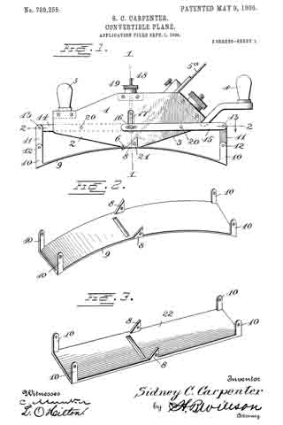
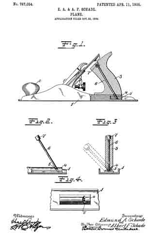
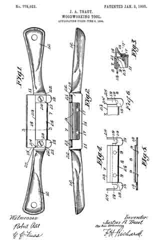
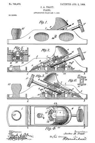
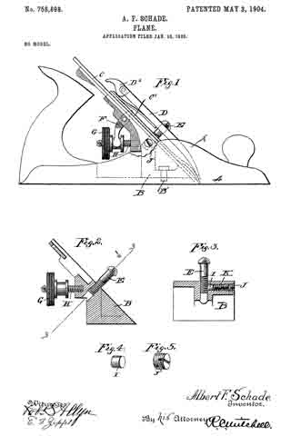
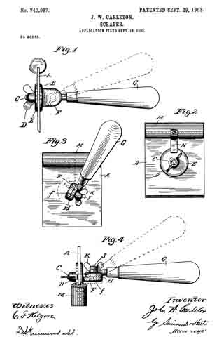
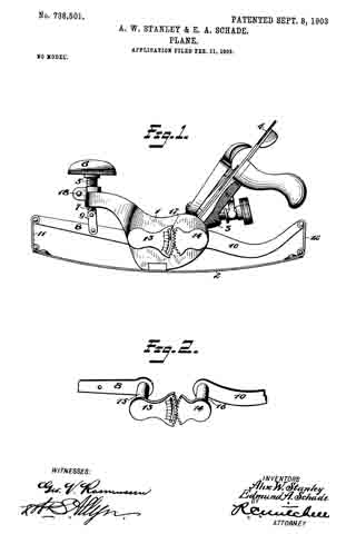
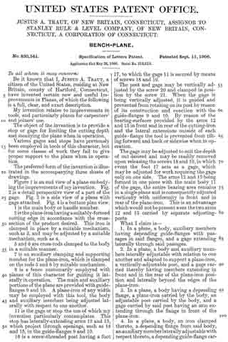
Figure 1 is an end view of a plane embodying the improvements of my invention. Fig. 2 is a detail perspective view of a part of the gage. Fig. 3 is a side view of a plane with gage attached. Fig. 4 is a bottom plan view.

1 is the main body or handle member.

2 is the plane-iron having a suitably-formed cutting edge in accordance with the cross-section of the product desired. This iron is clamped in place by a suitable mechanism, such as 3, and may be adjusted by a suitable mechanism, such as 4.

5 and 6 are cross-rods clamped to the body in a suitable manner.

7 is an auxiliary clamping and supporting member for the plane-iron, which is clamped on the rods 5 and 6 by suitable mechanism.

8 is a fence customarily employed with planes of this character for guiding it laterally in operation. The main and auxiliary portions of the plane are provided with guide-flanges 9 and 10. A plane-iron of any width may be employed with this tool, the body and auxiliary members being adjusted laterally with respect to one another.

11 is the gage or stop the use of which my invention particularly contemplates. This stop has laterally-extending arms 12 and 13, which project through openings, such as 14 and 15, in the guide-flanges 9 and 10.

16 is a screw-threaded post having a foot 17, to which the gage 11 is secured by means of screws 18 and 19.

The post and gage may be vertically adjusted by the screw 20 and clamped in position by the screw 21. When the gage is being vertically adjusted, it is guided and prevented from rotating on its post by reason of its construction and coaction with the guide-flanges 9 and 10. By reason of the bearing-surfaces provided by the arms 12 and 13 in front and in rear ofthe cutting-iron and the lateral extensions outside of each guide-flange the tool is prevented from tilting forward and back or sidewise when in operation.

The gage may be adjusted to suit the depth of cut desired and may be readily removed upon releasing the screws 18 and 19, in which event the foot 17 acts as a gage, which maybe adjusted for work requiring the gage only on one side. The arms 12 and 13 being formed in one piece with the main body 11 of the gage, the entire bearing area remains in a single plane and is consequently adjusted vertically with uniformity in front and in rear of the plane-iron. This is an advantage which would not be present were the two arms 12 and 13 carried by separate adjusting-posts.

What I claim is —

1. In a plane, a body, auxiliary members having depending guide-flanges with passages in said flanges, and a gage extending laterally through said passages.

2. In a plane, a body and auxiliary members laterally adjustable with relation to one another and adapted to support a plane-iron, a vertically-adjustable post, and a gage carried thereby having members extending in front and in the rear of the plane-iron position and laterally beyond the edges of the plane-iron.

3. In a plane, a body having a depending flange, a plane-iron carried by the body, an adjustable post carried by the body, and a gage carried by said post having an arm extending through the flange in front of the plane-iron.

4. In a plane, a body, an iron clamped thereto, a depending iiange from said body, an auxiliary member laterally adjust able with respect thereto, a depending guide-flange carried by said auxiliary member, and a vertically-adjustable gage in the rear of the plane-iron position extending through said flanges.

5. In a plane, main and auxiliary sections, depending flanges carried thereby, a plane-iron held between said sections, a vertically-adjustable post having a foot, and a gage removably secured to said foot and having an arm extending through said flanges.

6. In a plane, main and auxiliary sections, depending flanges carried thereby, a plane-iron held between said sections, a vertically-adjustable post having a foot, and a gage removably secured to said foot and having arms extending through said flanges in front and in the rear of the plane-iron.

7. As an article of manufacture, a plane-gage attachment comprising a body, means of attachment to a plane, and laterally-extending arms carried by the body spaced apart from each other and lying in the same plane with the body.

JUSTUS A. TRAUT.

Witnesses:
W. J. WORAM,
H. S. WALTER.

No. 824,954 – Plane (John H. Shaw) (1906)

[paiddownloads id=”633″]824954


UNITED STATES PATENT OFFICE.

_________________

JOHN H. SHAW, OF NEW HAVEN, CONNECTICUT, ASSIGNOR TO SARGENT AND COMPANY,
OF NEW HAVEN, CONNECTICUT, A CORPORATION OF CONNECTICUT.

PLANE.

_________________

824,954. Specification of Letters Patent. Patented July 3, 1906.
Application filed April 17, 1903. Serial No. 153,092.

_________________

To all whom it may concern:

Be it known that I, JOHN H. SHAW, of the city and county of New Haven, State of Connecticut, have invented new and useful Improvements in Planes, of which the following is a full, clear, and exact description when taken in connection with the accompanying drawings, which form a part thereof, and in which —

Figure 1 represents a central vertical section, the ends being shown in elevation, of a plane embodying my invention; Fig. 2, a plan view of the bed of the plane; Fig. 3, a vertical transverse section on lines 3 3 of Fig. 1; Fig. 4, a longitudinal vertical section on lines 4 4 of Fig. 3 of a portion of the plane; Fig. 5, a similar view, the bit being shown in a different adjustment; and Fig. 6 is a perspective view of the support E.

In all figures similar letters of reference represent like parts.

This invention relates to planes, and has for its object the production of a plane in which the frog may be adjusted longitudinally and clamped in place after the bit is clamped to the frog.

in the proper adjustment of the bit of a plane it is necessary to move the bit longitudinally on the frog, so that the cutting edge will project more or less through the throat of the frame according to the depth of the cut desired. When properly adjusted, it is necessary in order that the bit may be held firmly in place that its cutting end should rest against the rear of the throat and against the frog. Owing to the variations in the angle to which the bit is ground, the adjustment of the bit longitudinally on the frog may affect its position in the throat and against the frog. It is an important desideraturn, therefore, in order to prevent what is known as “chattering,” which occurs when the lower end of the bit is not held firmly against the throat and frog, that the frog may be adjusted on the frame after the bit is adjusted longitudinally on it, because were it necessary to remove the bit in order to adjust the frog a number of attempts might be required to establish the exact relation between the frog and throat and beveled end of the bit.

To this end my invention resides in the production of a novel construction by which the adjustment of the frog may be made from the rear after the bit is secured to the front face of the frog, as set forth and claimed hereinafter, together with other minor improvements.

Referring to the drawings for a more particular description, the parts designated by the letter A represent the frame or stock of the plane, and a the throat thereof, which extends transversely across the bottom.

B is a raised portion near the middle of the frame having screw-holes b and a vertical flange b’ at right angles to the plane, provided with a substantially semicircular groove b2.

C’ represents the bit or plane iron, to which is secured b the screw c the cap-iron D. The forward end d of the cap-iron D is bowed outward in well-known manner.

E is a frog or support for the bit adapted to rest on the raised portion B of the frame A and having a depending portion e, adapted to rest on the frame A immediately in the rear of the throat a.

F is a screw projecting from the front of the support E, the head of which is adapted to engage and hold in place the clamping-cap G. The forward end of the clamping-cap G bears on the bowed portion d of the cap-iron D, and pivoted to the rear end of the clamping-cap is a cam-clamp H, adapted to bear on a spring-plate it to lock the cap in place between the engaging head of the screw F and the cap-iron D.

I designates a set-screw secured to said support and on which is mounted a nut J, having an annular groove j, engaged by the forked end k of a bell-crank lever K, plivoted at k’ to the support, and having its other end k2 engage the cap-iron D in well-known manner. By means of the nut J and lever K the cap-iron D and the bit C, secured thereto, are adjusted longitudinally on the forward inclined face of the support E.

L is a lever pivoted to the support at l, adapted to engage the screw c, connecting the bit C and cap-iron D. By means of the lever L the bit may be adjusted transversely in well-known manner.

M is an adjusting-screw adapted to be screwed into the rear of the support and having on its head an annular groove m, adapted to be engaged by a flange b’ on the frame of the plane. The support E has lateral projecting portions e’ upon its respective sides and preferably extending to the rear of the body portion thereof, and e” designates upright arms on said projecting portions connecting with the body portion.

O designates one or more clamping-screws adapted to extend through longitudinal slots P in the projecting portions of the support and engage in internally-threaded screw-holes b in the frame.

By this construction it is possible to adjust and clamp the support in place after the bit is properly mounted on the support, for after the bit is so mounted the clamping-screws O may be loosened and the support moved forward or backward by the adjusting-screw M.

Having now described my invention, what I claim, and desire to secure by Letters Patent, is —

1. In a plane, the combination with a frame, of a bit, a throat in said frame throihgh which said bit may project, a longitudinally-adjustable frog or support carrying the bit-adjusting means, a part carried by the support and projecting rearwardly of the bit-adjusting means, an clamping means for retaining the support in adjusted position, said clamping means being arranged to engage said projecting part of the support at a spaced distance from the body part thereof, whereby it is accessible when the bit is mounted on the support.

2. In a plane, the combination with a frame, of a bit, a throat in said frame through which said bit may project, a bodily-adjusting means, and means for clamping said support in its adjusted position carried by a rearwardly-projecting portion of the frog and accessible when the bit is mounted on said support.

3. In a plane, the combination with a frame, of a bit, a throat in said frame through which the bit may project, a movable support on said frame to the rear of said throat and carrying the bit-adjusting means, an adjusting-screw for adjusting said support longitudinally of said frame from the rear of said support, and a clamping screw or screws adapted to hold said support in its adjusted position, said screw or screws being carried by a rearwardly-projecting part of the support and accessible when said bit is in place on said support.

4. In a plane, the combination with a frame having a portion substanially parallel to the bottom thereof, of a bit, a throat in said plane through which the bit may project, a support carrying the bit-adjusting means on said frame capable of moving longitudinally on said parallel portion of said frame, a slot in a rearwardly-projecting portion of said support, and a clamping-screw passing through said slot into said frame to hold the support from movement on said frame, whereby said clamping-screw is accessible for mampulation while said bit is in place on said support.

In witness whereof I have hereunto set my hand on the 28th day of February, 1903.

JOHN H. SHAW.

Witnesses:
LE ROY J. KIRKHAM,
ALICE A. WILSON.

No. 818,472 – Plane (Henry B. Sargent) (1906)

[paiddownloads id=”630″]818472


UNITED STATES PATENT OFFICE.

_________________

HENRY B. SARGENT, OF NEW HAVEN, CONNECTICUT, ASSIGNOR TO SARGENT & COMPANY,
OF NEW HAVEN, CONNECTICUT, A CORPORATION OF CONNECTICUT.

PLANE.

_________________

818,472. Specification of Letters Patent. Patented April 24, 1906.
Application filed August 15, 1904. Serial No. 220,834.

_________________

To all whom it may concern:

Be it known that I, HENRY B. SARGENT, of the city and county of New Haven and State of Connecticut, have invented new and useful Improvements in Planes, of which the following is a full, clear, and exact description when taken in connection with the accompanying drawings, which form a part thereof, and in which —

Figure 1 represents a side elevation of a plane embodying the invention; Fig. 2, a bottom view of the same; Fig. 3, an enlarged plan view; Figs. 4 and 5, longitudinal sectional views on line 4 4 of Fig. 3, the parts being shown in different positions , Figs. 6 and 7, top and side detail views, respectively, of the adjustable mouthpiece ; Fig. 8, a bottom detail view of the adjusting-cam, and Fig. 9 a transverse vertical section of the plane-bottom on line 9 9 of Fig. 3.

In all figures similar letters of reference represent like parts.

This invention relates to planes, and has for its object the production of a plane having a novel, simple, and efficient throat adjustment; and to this end it consists in the improvements and combinations of parts set forth and claimed hereinafter.

Referring to the drawings for a more particular description, the part designated by the letter A represents the plane-bottom, and B the side walls. C designates the throat, and D the frog or plane-iron seat. E designates the bit or plane-iron, and F the cap, with the cap-screw G. H is the cam-lever, I the lateral adjustment-lever, and K the adjusting-screw controlling the longitudinal adjusting-lever L. These parts may be of any suitable construction and are not part of my improvement.

As shown in Figs. 2, 4, and 5, the bottom of the plane is cut away in front of the throat for the reception of a slide or mouthpiece M. A circular perforation N is provided in the forward part of the plane-bottom with an inwardly-projecting flange O, Fig. 9. A disk P is adapted to fit in said perforation and rest on said flange and has on its under side a cam or circular depending protuberance Q, eccentric to the center of the disk. A finger-piece R projects from the periphery of the disk P, and through the center of the disk is a perforation S.

On the upper side of the slide or mouth-piece M are lugs T, distant from each other the length of the diameter of the cam Q, Figs. 4 and 5, while between them is an upwardly-projecting screw V, adapted to extend through the perforation S in the disk P for the reception of a clamping-nut W, which also forms the forward, knob of the plane. The perforation S in the disk P is considerably wider than the diameter of the screw V, so that the disk may have a limited movement about the screw without contact therewith.

The operation of the device is as follows: When it is desired to change the adjustment of the throat from the position shown in Figs. 2, 3, and 4, the clamping-nut W is slightly turned to loosen the disk P and slide M, and the disk P is turned the necessary distance by means of the finger-piece R. The cam then bears against the rear lug T on the slide M and pushes the slide rearward, as shown in Fig. 5. The slide M then contracts the throat C the desired amount, and the parts are secured by screwing the clampin-nut W down on the screw V, so that the sIide will be held against the under side of the forward end of the bottom A of the plane and the disk forced down on the flange O in the perforation N. To open the throat, it is only necessary to unscrew the nut W and loosen the parts to operate them in the reverse direction.

It will be seen that the cam depending from the disk engages the mouthpiece in an immediately adjacent plane, so that the operation is direct, and the coacting parts will be protected by the disk from dust, chips, or the like.

Having now described my invention, what I claim, and desire to secure by Letters Patent, is —

1. In a plane, the combination with a stock, of a throat in the bottom thereof, a sliding mouthpiece for varying the size of said throat, a disk fitted in a circular seat to rotate on said stock and having a depending cam between said stock and said mouthpiece adapted to engage said mouthpiece to operate the same, and protected by said disk, and means for locking said mouthpiece.

2. In a plane, the combination with a stock, of a throat in the bottom thereof, a sliding mouthpiece for varying the size of said throat, a disk fitted in a circular seat to rotate on said stock and having a depending cam between said stock and said mouthpiece adapted to engage projections on said mouth-piece in an immediately adjacent plane to operate the same, and protected by said disk, and means for locking said mouthpiece.

3. In a plane, the combination with a stock, of a throat in the bottom thereof, a sliding mouthpiece for varying the size of said throat, a disk fitted in a circular seat to rotate on said stock and having a perforation and a depending cam between said stock and said mouthpiece adapted to engage integral projections on said mouthpiece in an immediately adjacent plane to operate the same, and protected by said disk, and means for locking said mouthpiece, including a screw-threaded post on said mouthpiece projecting through said perforation in said disk, and a nut on said post adapted to bind said disk on said stock to prevent movement thereof.

4. In a plane, the combination with a stock, of a throat in the bottom thereof, a sliding mouthpiece for varying the size of said throat, a disk mounted on said stock and having a depending cam and a perforation, oppositely-disposed integral lugs on said mouthpiece adapted to be engaged by said cam, a screw-threaded post on said mouth-piece projecting through said perforation in said disk in which it is capable of lateral play, and a nut on said post adapted to bind said disk on said stock to prevent movement of said mouthpiece, the nut being arranged to overlap the wall surrounding the aperture of the disk.

5. In a plane, the combination with a stock, of a throat in the bottom thereof, a sliding mouthpiece for varying the size of said throat, a disk fitted in a circular seat to rotate on said stock and having a depending cam between said stock and said mouthpiece adapted to engage integral projections on said mouthpiece in an immediately adjacent plane to operate the same and protected by said disk, a projecting finger-piece on the upper surface of the disk, and means for locking said mouthpiece from movement.

In witness whereof I have hereunto set my hand on the 11th day of August, 1904.

HENRY B. SARGENT.

Witnesses:
L. F. BREESE,
WILLIAM A. RICE.

No. 789,255 – Convertible Plane (Sidney C. Carpenter) (1905)

[paiddownloads id=”620″]789255


UNITED STATES PATENT OFFICE.

_________________

SIDNEY C. CARPENTER, OF WEST HARTFORD, CONNECTICUT.

CONVERTIBLE PLANE.

_________________

SPECIFICATION forming part of Letters Patent No. 789,255, dated May 9, 1905.
Application filed September 1, 1904. Serial No. 223,046.

_________________

To all whom it may concern:

Be it known that I, SIDNEY C. CARPENTER, a citizen of the United States, residing at West Hartford, in the county of Hartford and State of Connecticut, have invented certain new and useful Improvements in Convertible Planes; and I do declare the following to be a full, clear, and exact description of the invention, such as will enable others skilled in the art to which it appertains to make and use the same.

My invention relates to convertible planes of that character designed to be used for planing curved or flat surfaces; and the objects of same are to provide a plane with a spring bearing-surface which may be readily and quickly adjusted to the required degree to bear upon surfaces of more or less curvature and which may be readily converted into a plane of the ordinary or usual construction provided with a flat bearing-surface.

Another object is to provide a plane of this character which may be quickly and accurately adjusted for use under varying conditions and which will be provided with means for adjusting cutting-blades or bits relatively, accurately, and quickly.

These and other objects are attained by means of the construction illustrated in the accompanying drawings, in which —

Figure 1 is a side view of a plane constructed in accordance with my present invention and having the curved spring bearing-plate secured thereto. Fig. 2 is a perspective view of the spring bearing-plate detached from the plane. Fig. 3 is a perspective view of the fiat plane-surface which may be substituted for the spring when it is desired to convert the device into an ordinary plane. Fig. 4 is a vertical section on the line 1 1, Fig. 1. Fig. 5 is a longitudinal section on the line 2 2, Fig. 1.

Referring to the drawings for a more particular description of my invention, the numeral 1 designates the body portion of the plane, said body portion being oppositely inclined in front and rear, as shown at 2 3, and provided with suitable handles 4 5 and a cutter or bit 5a. A transverse slightly-curved surface 6 is provided at the central lower portion of the stock or body, and a lug 8, extending upward from the curved steel plate 9, is secured to the stock by a bolt 21, said plate forming the bottom or bearing surface of the plane. Near opposite ends of the plate 9 are lugs 10, projecting upward, said lugs being connected to links 11, pivoted at 12 and connected at their upper ends at 13 to longitudinal levers 14 and 15. Said levers 15 extend toward the middle of the frame upon opposite sides thereof and are connected by a pin 16, extending through the body or stock of the plane and through the front levers 14, a link 17 connecting said levers with a pivoted bolt 18, having fitted thereon a nut 19 for adjusting the levers 14 15 upon their pivots 20 to raise or lower the links 11, and thus adjust the spring-plate 9 to the required curvature for the work to be operated upon.

If it is desired to convert the plane into one of ordinary construction, the bolt 21 may be removed and the plate 22 substituted for the spring-plate in an obvious manner.

From the foregoing it will be obvious that my plane is of comparatively simple construction and may be readily converted from a circular to a flat-bottom plane. The curved steel plate may be readily adjusted to the required degree, depending upon the degree of curvature of the work to be performed.

Having thus described my invention, what I claim as new, and desire to secure by Letters Patent, is —

A plane comprising a stock having oppositely-inclined bottom faces, a spring face-plate secured to said stock between said inclined surfaces, said face-plate having upwardly-extending end lugs, links pivoted to said lugs, levers pivoted to said links and extending longitudinally to the center of the stock, a pin connecting the meeting ends of said levers, a link connected to said pin, a bolt connected to said link, and a nut for adjusting the bolt, the levers and the spring, substantially as described.

In testimony whereof I have hereunto set my hand in presence of two subscribing witnesses.

SIDNEY C. CARPENTER.

Witnesses:
JOSEPH P. KENNEDY,
JOHN D. WOOD.

No. 787,054 – Plane (Edmund A. Schade And Albert F. Schade) (1905)

[paiddownloads id=”618″]787054


UNITED STATES PATENT OFFICE.

_________________

EDMUND A. SCHADE AND ALBERT F. SCHADE, OF NEW BRITAIN, CONNECTICUT, ASSIGNORS TO
STANLEY RULE & LEVEL COMPANY, OF NEW BRITAIN, CONNECTICUT, A CORPORATION OF CONNECTICUT.

PLANE.

_________________

SPECIFICATION forming part of Letters Patent No. 787,054, dated April 11, 1905.
Application filed October 22, 1904. Serial No. 229,520.

_________________

To all whom it may concern:

Be it known that we, EDMUND A. SCHADE and ALBERT F. SCHADE, citizens of the United States, residing at New Britain, Hartford county, Connecticut, have invented certain new and useful Improvements in Planes, of which the following is a full, clear, and exact description.

Our lnvention relates to improvements in planes.

The object of the invention is to provide a plane with an adjustable tilting handle, so that it may be grasped by the hand and operated in many positions and cases where at present a plane cannot be used except with great danger of accident to the knuckles and the back of the hand, which are liable to be bruised.

The invention is illustrated in the accompanying single sheet of drawings.

The body of the plane carries a bearing for the handle, so that the handle can be tilted to either side and secured in place or used in a vertical position, as is customary.

Figure 1 is a side elevation of a plane, showing those parts which embody the improvements of our invention in vertical section. Fig. 2 is a fragmentary detail showing the parts for securing the handle in position. Fig. 3 is a vertical cross-section showing the method of attachment. Fig. 4 is a plan view of a fragment of the body of a plane, showing the bearing for the handle.

1 indicates the body of a plane, which may be of any suitable character and constructed of any suitable material. The frame herein shown is made of cast-iron.

2 is a knob which may conveniently be provided at the front end of the plane, as is common.

3 is a handle of suitable conformation and material.

4 is a bearing for the handle, which extends lengthwise of the body for some distance. This is shown integral with the body; but it is obvious that it may be made separate and bolted or riveted or otherwise secured in place.

5 is a pin or roller which is mounted in the bearing-block 4 and adapted to rotate or oscillate from side to side through a limited extent.

6 is a rod which is screw-threaded at the lower end and takes into the pin 5.

7 is a screw-cap cooperating with the upper end of the rod 6 for securely clamping the parts together.

The parts are preferably assembled by first attaching the rod 6 to the pin 5, then slipping the handle member 3 over the rod 6, and lastly fixing the cap 7 in place. By tightening the cap the handle may be securely held in place on its seat on the bearing-block 4 in any position, as indicated, for instance, in dotted lines in Fig. 3, While this construction is exceedingly simple, it does provide a means for avoiding such accidents as in the past have been quite common when using an ordinary plane in certain positions — such as, for instance, planing deep rabbets or when operating upon jack-boards. The handle, moreover, may be secured in place in the ordinary upright position for usual work.

It is obvious that many changes may be made in the details of construction without departing from the spirit or scope of our invention.

What we claim is —

1. In a plane, the combination of a body or stock portion having a long semicylindrical bearing, a handle member having a corresponding semicylindrical bearing, a pin mounted to oscillate in the body portion and a rod passing through said handle member and secured to said pin with means to coact therewith for clamping the handle in position at different angular positions.

2. In a plane, the combination of a body or stock portion having a longitudinal bearing, a handle tiltingly seated thereon, a pin mounted in said body portion and a rod passing through said handle and screwed into said pin with means for coasting therewith and clamping said handle in position.

3. In a plane the combination of a body portion having a bearing, a handle mounted to tilt thereon, a pin rotatably mounted in said stock portion beneath said bearing, a rod passing through said handle and screw-seated in said pin and a cap coacting with said rod and said handle and accessible for clamping said handle in position.

Signed at New Britain, Connecticut, this 20th day of October, 1904.

EDMUND A. SCHADE.
ALBERT F. SCHADE.

Witnesses:
W. J. WORAM,
E. G. HOFFMAN.

No. 780,064 – Plane (Arthur J. Reynolds) (1905)

[paiddownloads id=”616″]780064


UNITED STATES PATENT OFFICE.

_________________

ARTHUR J. REYNOLDS, OF NEW BRITAIN, CONNECTICUT, ASSIGNOR TO THE STANLEY RULE & LEVEL COMPANY, OF NEW BRITAIN, CONNECTICUT, A CORPORATION OF CONNECTICUT.

PLANE.

_________________

SPECIFICATION forming part of Letters Patent No. 780,064, dated January 17, 1905.
Application filed June 10, 1904. Serial No. 211,580.

_________________

To all whom it may concern:

Be it known that I, ARTHUR J. REYNOLDS, a citizen of the United States, residing at New Britain, in the county of Hartford, State of Connecticut, have invented certain new and useful Improvements in Planes, of which the following is a full, clear, and exact description.

My invention relates to improvements in planes, and particularly to an adjusting-lever for the plane-iron.

The object of my invention is to simplify the construction of the same, lessen the cost of manufacture, and increase the general efficiency and ease of operation.

Figure 1 is a side elevation of a plane embodying the improvements of my invention. Fig. 2 is a side view, on an enlarged scale, of what may be termed the “adjusting-lever.” Fig. 3 is a top view of the same. Fig. 4 is a plan of a blank of sheet of wrought metal from which the adjusting-lever is formed.

1 indicates the body of the plane of suitable construction. The form herein is shown with a rear handle 2 and a front handle 3.

4 is a frog secured to the body portion by any suitable means.

5 is a cutting-iron of usual construction.

6 is a plate which may be used to reinforce the plane-iron and also afford a convenient means for cooperating with the adjusting mechanism.

7 is a cap-screw secured to the frog.

8 is a cap and 9 a clamping member.

All of the parts thus far described may be of any suitable construction.

The form of my invention which I have illustrated employs what is known as the “Y adjusting-lever” for varying the cutting depth of the plane-iron. This member is pivoted on pin 10, ordinarily carried by the frog 4. The adjusting-lever is formed of wrought or sheet metal blanked out in the form shown in Fig. 4 and afterward shaped up into the form shown in Figs. 1, 2, and 3. 11 indicates one of the ends of the duplex nose, which fits into a suitable recess in the plate 6, as is common. 12 indicates one end or arm of the adjusting-lever. 13 is the connecting portion in the form of a U bend between the two side arms and the duplex nose. This construction affords a broad bearing upon the pin 10 with the use of a small amount of metal, which is consequently economical and light in weight. The distance between the ends of the duplex nose affords a broad bearing for engagement with the plane-iron or plate.

14 is a post carried by the frog 4, and 15 is a sleeve which operates on the post 14 for cooperating with the arms 12 12 of the adjusting-lever. By means of this sleeve 15 the position of said lever may be varied to vary the depth of the cutting-iron as desired.

The forming of the adjusting-lever as shown affords great strength, since the U bend increases the strength at this point materially. The fiber of the metal is also so disposed at the point of contact with the plane-iron as to give a minimum amount of friction. The advantages of such a construction will be apparent to those skilled in the art.

What I claim is —

A plane-iron adjusting lever shaped to form arms at the respective ends for engaging the adjusting and the adjusted parts and an enlarged intermediate fulcrum portion comprising two side members united by a bend.

Signed at New Britain, Connecticut, this 6th day of June, 1904.

ARTHUR J. REYNOLDS.

Witnesses:
H. S. WALTER,
W. J. WORAM.

No. 778,922 – Woodworking-Tool (Justus A. Traut) (1905)

[paiddownloads id=”613″]778922


UNITED STATES PATENT OFFICE.

_________________

JUSTUS A. TRAUT, OF NEW BRITAIN, CONNECTICUT.

WOODWORKING-TOOL.

_________________

SPECIFICATION forming part of Letters Patent No. 778,922, dated January 3, 1905.
Application filed June 6, 1904. Serial No. 211,258.

_________________

To all whom it may concern:

Be it known that I, JUSTUS A. TRAUT, a citizen of the United States, residing in New Britain, in the county of Hartford and State of Connecticut, have invented certain new and useful Improvements in Woodworking-Tools, of which the following is a specification.

This invention relates to woodworking tools or implements of the general class in which cutters are adjustably fixed in place — as, for instance, in spokeshaves and analogous artices.

My present improvement relates to the construction and mounting of the cutter and of the means for attaching the cutter and adjusting the same on the tool or implement.

For the purpose of illustrating my present improvement I have shown the same applied to a spokeshave.

In the drawings accompanying and forming a part of this specification, Figure 1 is a plan view of a spokeshave provided with my present improvements. This view is taken with the cutter uppermost, this arrangement being adopted for convenience of illustration. Fig. 2 is a side elevation as seen from the right hand in Fig. 1. Fig. 3 is a cross-sectional view in line 3 3 of Fig. 1. Fig. 4 is a plan view of the cutter mounted on its carrier. Fig. 5 is a side elevation thereof as seen from the right hand, and Fig. 6 shows an alternative form of the end stops on the blade-carrier.

One of the features of the present improvements relates to the manner in which the cutter is mounted on the implement and by which the strains due to the clamping down of the retaining or binding devices are applied directly to a cutter-carrier, this being accomplished in such a manner as to leave the cutter normally free of such strain or cramping action as would tend to interfere with the proper holding of the same or would tend to spring and deflect the cutter.

My present improvements in the preferred form in which I have illustrated them in the present case are adapted for holding the cutter rigidly in place without applying pressure against the ends of the cutter, and at the same time the clamping of the cutter-carrier is effected by a direct pressure in one direction I only and is accomplished by the clamping action applied to relatively large surfaces, thus producing an efdcient holding of the parts together without producing the deiiection of the cutter or injurious strains in any part of the same. In this connection it will be remembered that the steel of which the cutter edge should be made must be of a high quality, whereas a more ductile and flexible quality of metal is desirable for use in making the carrier or any part of the implement which is subjected to intense strains or pressure. By means of the construction herein illustrated these objects are accomplished, the cutter proper (designated in a general way by 7) being made of relatively hard steel of high quality, while the carrier (designated in a general way by 8) is made of sheet steel or other suitable metal of a relatively tough and flexible character.

Another feature of the improvement relates to the manner of connecting the cutter onto its carrier by uniting the parts together by attaching devices — as, for instance, the rivets 9, located at some distance from the ends 10 of the cutter. In this way I obtain flexibility of the end portions of the carrier, allowing these to spring somewhat, and thus holding the cutter firmly in place without subjecting the cutter-blade itself to the deflecting strain. By this means a slight springing of the implement is prevented from affecting the fastening of the cutter in place, either as to the position of the cutter or the degree of security with which it is held, and by this means also I provide for using a lesser degree of precision in the making of the several parts, as well as for the complete interchangeability of the cutters with a lesser degree of precision in the manufacture of the implement, all of which results and objects are of practical importance and value in this art.

The stock of the tool is designated in a general way by 11 and comprises hand-grips 12 and a body portion 13, to which a sole-carrying member or guard-plate 15 is adjustably secured, the sole 16 whereof may be adjusted relative to the plane of the blade by means of set-screws 17, passing through elongated holes 17′ in the sole-carrying member. It will be seen that the ends 18 of the carrier project beyond the ends 10 of the blade and that they have ways 19 for suitable set-screws 20 for securing the blade to the body of the stock. Blocks 21 may be placed upon the top of the end portions of the carrier and lie between the ends of the blade and shoulders 22 of the stock to add to the finish of the instrument and to assist in the securernent of the carrier. The edge 23 of the blade may be adjusted toward and from the sole to regulate the cut by means of shifting the carrier back and forth and tightening the set-screws after it has been adjusted to the desired position.

It will be seen that the ends of the carrier project beyond the ends of the blade and that the carrier is secured to the blade inwardly of such ends whereby the strain of clamping or of working will be neutralized by the yieldability of the carrier to thereby protect and preserve the blade. The form of blade here employed is one made of a plate of metal having a cutting edge, as 23, along one of its sides, and the carrier is also in the form of a plate of metal overlaying the blade at the side or edge, as 26, opposite the cutting edge.

In using the implement the workman will from time to time grind away the edge 23 of the cutter-blade, the cutter being set forward toward the guard-plate or sole 15. The extending ends 24 of the said carrier are represented in Fig. 4 reaching forward to engage the edge or face 25 of the member 15 to limit the forward adjustment of the cutter, and it is intended that these ends when so constructed shall be ground away from time to time accordingly as the cutter-blade becomes narrower after continued use, so that said ends 24 of the carrier constitute stop devices for enabling the workman to set the cutter in the proper position. For convenience said stop ends are shown formed on the outer sides of the slots 19; but, if desired, they may be formed on the inner side of the said slot, or both sides, as indicated at 24 24′ in Fig. 6.

Having thus described my invention, I claim —

1. A cutting-tool embodying a stock, an unyielding blade, and a yieldable connection between the blade and stock andrrigidly secured to each.

2. In a woodworking-tool, the combination with a stock portion having a sole, of a resilient blade-carrier adjustably secured to the stock adjacent to the sole and intermediate the blade and stock, and a rigid blade having an edge and secured intermediate the ends of said edge to such carrier.

3. A woodworking-tool, comprising a stock portion, a rigid blade having a cutting edge, a relatively yieldable carrier rigidly secured to the blade inward of the ends of said edge and intermediate the blade and stock, and means for adjustably securing said carrier to the stock and engaging the same at points beyond the said ends of the blade edge.

4. A woodworking-tool comprising a stock portion, a rigid blade, a relatively yieldable carrier rigidly secured to the blade inward of its ends, means for adjustably securing said carrier to the stock, and stop-faces on the carrier to limit its forward adjustment.

5. A blade for a woodworking-tool, embodying a rigid plate having a cutting edge upon one side, a resilient carrier secured to the other side and projecting therebeyond and having securing means at such projecting portion.

6. A woodworking-tool having a stock, a guard carried thereby and adjustable relative to the position of the cutter, a cutter rigidly secured inwardly of its ends to a carrier; said carrier; means to secure the carrier to the stock; and stop-faces on the carrier to limit its forward adjustment.

7. In a woodworking-tool the combination with a stock, of a resilient carrier-bar clamped with one face adjacent to the stock, a rigid cutting-blade rigidly secured to the other face of said resilient bar sufficiently remote from its clamped portion to constitute the bar a resilient connection between the blade and the stock, and means to clamp said carrier-bar to the stock.

JUSTUS A. TRAUT.

Witnesses:
W. J. WORAM,
E. G. HOFFMAN.

No. 778,921 – Plane (Justus A. Traut) (1905)

[paiddownloads id=”612″]778921


UNITED STATES PATENT OFFICE.

_________________

JUSTUS A. TRAUT, OF NEW BRITAIN, CONNECTICUT, ASSIGNOR TO THE STANLEY RULE & LEVEL COMPANY, OF NEW BRITAIN, CONNECTICUT, A CORPORATION OF CONNECTICUT.

PLANE.

_________________

SPECIFICATION forming part of Letters Patent No. 778,921, dated January 3, 1905.
Application filed April 27, 1904. Serial No. 205,115.

_________________

To all whom it may concern:

Be it known that I, JUSTUS A. TRAUT, a citizen of the United States, residing at New Britain, in the county of Hartford, State of Connecticut, have invented certain new and useful Improvements in Planes, of which the following is a full, clear, and exact description.

My invention relates to improvements in planes and particularly to planes, in which cutters of various sizes and shapes may be interchangeably employed.

The object of the invention is to provide a construction in which interchanges of cutters may be effected readily and quickly and the operation of the same made reliable and efficient. I have also sought to employ as few parts as possible and to make the construction as economical as its large variety of functions make feasible.

The construction of my invention in the particular form as shown in the drawings consists of a main body portion and a relatively movable section between which the cutting-iron is secured and held in place. Adjustable and interchangeable sole portions are provided by means of which the plane may be guided and the cutting depth regulated with any form of cutting-iron. These adjustable sole portions also support and steady the plane-iron and permit the user to vary the size of the throat or opening in front of the cutting edge.

The details of construction will be more plainly seen on an inspection of the accompanying single sheet of drawings.

Figure 1 is a side elevation of a plane embodying the improvements of my invention. Fig. 2 is a front elevation of the same with the addition of adjustable auxiliary guide. Fig. 3 is a perspective view of a cutting-iron. Fig. 4 is a perspective view of the adjustable and interchangeable sole portions for employment with the plane of my invention.

1 indicates a main body or stock portion of the plane having a guide-blade 2.

3 is a handle which is conveniently provided.

4 is the plane-iron or cutter, which has its cutting edge formed to correspond with the outline of the work which it is desired to turn out.

5 is a suitable clamping-screw for securing the cutter in place.

6 is a screw for adjusting the cutting depth of the plane-iron.

7 and 8 are rods which extend from the body portion of the plane.

9 and 10 are screws for clamping in position.

11 is a sliding section which is upon the rods 7 and 8.

12 and 13 are thumb-screws for clamping the section in place at the distance desired from the main body portion.

14 and 15 are flanges to the front and rear of the throat of the plane which extend downward. The plane-iron when clamped in place is partially supported by the rear flange.

16 and 17 are portions of a sole which is provided to correspond with the shape of the cutter employed to limit the cutting depth and to guide and direct the plane in its operation. These sole portions are formed, preferably, of wood.

18 indicates two screws which take into the sole member 16 for clamping it to the forward flange 14. The flange is preferably provided with keyhole-openings, as shown, so that the sole portion may be removed without entirely removing the screws, it simply being necessary to loosen the screws, slide the sole forward, when the screws may be readily drawn through the enlarged portion. The rear flange 15 is provided with oppositely-positioned keyhole-openings, and the screws 19 coact therewith to clamp the rear sole portion 17 in position. Both of the sole portions may be adjusted front and rear, so as to vary the size of the throat in front of the cutter to bring the rear sole portion up so as to reinforce the cutter and prevent it from chattering or to remove the parts, as may be desired.

20 indicates a section of a molding being cut by a cutter, as shown in the drawings. The form of outline produced will of course depend upon the cutter employed. With my improved invention in use any form of cutter may be employed, it simply being necessary to make use of correspondingly-formed sole portions.

21 indicates a member which may be provided to slide on the rods 7 and 8 and carry an auxiliary guide 22 for fixing the distance of the cutter from the edge of a board, molding, or the like.

23 is a handle which is conveniently provided on this fence portion which serves as a rest for the left hand.

The advantages of my construction will be particularly apparent to those skilled in the manufacture of woodworking-tools and in their use. It greatly reduces the number of parts necessary for a wide variety of work and the expense of the same.

What I claim is —

1. In a plane the combination of a main body member, a member laterally adjustable relatively thereto having flanges projecting downward, said flanges having horizontal openings with enlarged ends, a cutter having an irregularly-shaped edge, a sole member for each of said flanges corresponding in shape to said cutter, and screws for removably securing said sole members to said flanges.

2. In a plane the combination of a main body member, a second member slidable laterally relatively thereto, a pair of flanges projecting downwardly from said slidable member and having an opening between the same, a sole portion carried by each of said flanges, and means for adjusting said sole portions, substantially as described.

3. In a plane, the combination of a body member, a second member laterally adjustable with relation thereto and adapted with said first member to support a plane-iron, a pair of flanges carried by said second member, one in front and the other in the rear, each of said flanges having a plurality of openings elongated liorizontally, the openings in said forward flange being enlarged on their forward ends, the openings in the rear flange being enlarged on their rear ends and a pair of removable sole portions with means coacting with said flanges and the elongated openings therein for securing said sole portions to said flanges.

Signed at New Britain, Connecticut, this 25th day of March, 1904.

JUSTUS A. TRAUT.

Witnesses:
W. J. WORAM,
ROBERT N. PECK.

No. 771,463 – Molding Or Beading Plane (Charles C. Crossley) (1904)

[paiddownloads id=”609″]771463


UNITED STATES PATENT OFFICE.

_________________

CHARLES C. CROSSLEY, OF NEW BRITAIN, CONNECTICUT.

MOLDING OR BEADING PLANE.

_________________

SPECIFICATION forming part of Letters Patent No. 771,463, dated October 4, 1904.
Application filed February 13, 1904. Serial No. 193,362. (No model.)

_________________

To all whom it may concern:

Be it known that I, CHARLES C. CROSSLEY, of New Britain, in the county of Hartford and State of Connecticut, have invented a new and useful Improvement in Molding or Beading Planes; and I do hereby declare the following, when taken in connection with the accompanying drawings and the letters of reference marked thereon, to be a full, clear, and exact description of the same, and which said drawings constitute part of this specification, and represent, in —

Figure 1, a side view of a plane containing a cutter constructed in accordance with my invention; Fig. 2, a bottom view thereof; Fig. 3, a side view of the lower end of the cutter detached; Fig. 4, a front view of the same; Fig. 5, a perspective view of the cutter looking at the rear; Fig. 6, an outline of the cutting edge; Fig. 7, a sectional view of a block showing a single cut; Fig. 8, a similar view with two cuts; Fig. 9, a similar view with three cuts; Fig. 10, a plan view of a block showing cuts made at right angles.

This invention relates to an improvement in molding or beading planes, and particularly to the cutters therefor, the object of the invention being to so form the cutter that it may be used in stocks of ordinary construction and by which beads may be cut in every direction and, if desired, at angles to each other; and the invention consists in the construction as hereinafter described, and particularly recited in the claim.

In carrying out my invention I employ a stock A, which may be a center-bead stock, as shown, or a side-bead stock, having the usual mortise B for the reception of a cutter C, which is held in place by the usual wedge D. The operating edge of the cutter has a central half-round portion E, horizontal lower cutters F, and upwardly-extending side cutters or lips G, the end of the cutter being so formed that the cutting edges of the lower critters F are in rear of the cutting edge of the center portion E, whereby a drawing cut is made which assists in cutting smoothly and in any direction as regards the grain of the wood.

The plane is operated in the usual manner and if used upon the surface of wood the first cut will form a half-round bead H, with grooves I on opposite sides thereof, the outer walls of the grooves being straight, as shown in Fig. 7. If two beads are desired, the plane is moved to one side, so that one of the cutters F and the lip G ride in the groove formed at one side of the half-round bead H, which forms a guide for the plane and allows the central portion of the cutter to form a second half-round bead J and a groove K at one side, having a straight side wall, as shown in Fig. 8, or three beads may be formed, as shown in Fig. 9, and this can be continued indefinitely. In Fig. 10 of the drawings I have shown beads L and M crossing each other at right angles, and, as before stated, with my improved cutters these beads may be formed in any direction.

Having fully described my invention, what I claim as new, and desire to secure by Letters Patent, is —

In a plane, the combination with the stock, of a cutter having a central rounded cutting edge, straight cutters on opposite sides of the center and in rear thereof, and side cutters or wings extending upward and forward therefrom, substantially as described.

In testimony whereof I have signed this specilication in the presence of two subscribing witnesses.

CHARLES C. CROSSLEY.

Witnesses:
AARON DANIELSON,
CHAS. A. ERICSON.

No. 769,408 – Plane (Edmund A. Schade) (1904)

[paiddownloads id=”608″]769408


UNITED STATES PATENT OFFICE.

_________________

EDMUND A. SCHADE, OF NEW BRITAIN, CONNECTICUT, ASSIGNOR TO STANLEY RULE & LEVEL COMPANY, OF NEW BRITAIN, CONNECTICUT, A CORPORATION OF CONNECTICUT.

PLANE.

_________________

SPECIFICATION forming part of Letters Patent No. 769,408, dated September 6, 1904.
Application filed June 4, 1904. Serial No. 211,073. (No model.)

_________________

To all whom it may concern:

Be it known that I, EDMUND A. SCHADE, a citizen of the United States, residing at New Britain. in the county of Hartford, State of Connecticut, have invented certain new and useful lmprovements in Planes, of which the following is a full, clear, and exact description.

My invention relates to improvements in planes.

The object of my invention is to provide means for adjustment of the plane-iron and means for locking the same to prevent accidental movement.

The invention consists in improvements the principles of which are illustrated in the accompanying single sheet of drawings.

Figure 1 is a side elevation of a plane embodying the improvements of my invention. Fig. 2 is a detail fragmentary view showing the parts particularly necessary for comprehension out my improvement, a portion of the figure being shown in section.

1 indicates the body of a plane of any suitable construction. This in the form shown has handles 2 and 3. 4 is a frog of any suitable construction which provides a bearing for the plane-iron 5. 6 is a plate winch serves to reinforce the plane-iron and in this particular instance affords the means of connection for the adjusting mechanism. 7 is a cap-screw which takes into the frog in any well-known manner. 8 is a cap coacting therewith, and 9 is a clamp for holding the parts in their proper position. All of these parts thus far described may be of any suitable construction.

The cutting depth or position of the plane-iron may be varied by means of a lever, which is commonly termed a “Y adjustment.”

In the drawings, 10 indicates a pivot-pin carried by the frog and upon which the adjustment-lever is mounted.

11 is the nose of the lever, and 12 is one of the depending arms.

13 is a screw-post which is securely fastened to the frog 4.

14 is an operating-sleeve mounted to operate on the post 13 and having, preferably, a milled head 15.

16 is a shoulder or flange carried by the inner end and adapted to coact with the arm 12 of the adjusting-lever.

17 is a member which is carried by the sleeve 14. This aliords a bearing for one side of the arm 12 of the Y adjustment, so that when the sleeve 14 is moved longitudinally on the post 13 the arm 12 is rocked to and fro to move the cutting-iron.

The adjusting-sleeve 14; as commonly constructed is likely to accidentally turn and move on the post 13 as the plane is used. This results sometimes in derangement of the adjustment of the plane and at all times tends to wear the parts unduly. By my construction this is avoided. The member 17 is preferably milled on the edge and may be adjusted on the post 14 to securely engage the arm 12 and clamp the same in position against the flange 16. The friction of the parts against the arm 12 serves to prevent the adjusting-sleeve from rotating on the post 13. As a consequence the adjusting-lever cannot move and the sleeve has no free play to cause wear on the parts. The plane-iron may be adjusted by releasing the clamping mernber 17 and then operating the adjusting-sleeve. The advantages of this construction will be apparent to those skilled in this art.

What l claim is —

1. In a plane, the combination of a body portion, a frog, a plane-iron and adjusting member, a post, a sleeve adjustable on said post and coacting with said member and a clamping member mounted on said sleeve and also coacting with said member for the purpose specified.

2. In a plane, the combination of a body portion, a frog, a plane-iron, an adjusting member coasting therewith, a screw-threaded post, an adjusting-sleeve screw-threaded on said post, a clamping-sleeve screw-threaded on said adjusting-sleeve and rotatable therewith and also independently thereof said sleeve and clamping member coacting with said adjusting member for the purpose specified.

Signed at New Britain, Connecticut. this 1st day of June, 1904.

EDMUND A. SCHADE.

Witnesses:
H. S. WALTER,
W. J. WORAM.

No. 766,473 – Plane (Justus A. Traut) (1904)

No. 766,473 – Plane (Justus A. Traut) (1904)

[paiddownloads id=”606″]766473


UNITED STATES PATENT OFFICE.

_________________

JUSTUS A. TRAUT, OF NEW BRITAIN, CONNECTICUT, ASSIGNOR TO THE STANLEY RULE &
LEVEL COMPANY, OF NEW BRITAIN, CONNECTICUT, A CORPORATlON OF CONNECTICUT.

PLANE.

_________________

SPECIFICATION forming part of Letters Patent No. 766,473, dated August 2, 1904.
Application filed January 7, 1904. Serial No. 188,049. (No model.)

_________________

To all whom it may concern:

Be it known that I, JUSTUS A. TRAUT, a citizen of the United States, residing at New Britain, in the county of Hartford, State of Connecticut, have invented certain new and useful Improvements in Planes, of which the following is a full, clear, and exact description.

My invention relates to improvements in planes.

The object of the invention is to provide a plane of a simple and reliable construction which may be employed in the usual manner or reversed, as in double-ended planes, and adjusted to vary the cutting depth of the plane-iron.

The invention consists in employing, in a plane-body having two throats or openings, one in the plane near the front end and the other near the opposite or rear end, a pivoted step or yoke midway between two inclined guideways, with which coacts an adjusting-screw, one portion of the screw coacting with a block slidable upon either one of the inclined guides to adjust the plane-iron.

Details of the improvement will be more plainly seen on an inspection of the accompanying single sheet of drawings, in which —

Figure 1 is a side elevation of a plane embodying the improvements of my invention. Fig. 2 is a longitudinal section of the same, the front handle being, however, broken away and the operating parts shown in position with the plane-iron at the front opening or throat. Fig. 3 is a longitudinal section of a plane embodying my improvement with the parts reversed, showing the plane-iron adjusted through the rear throat or opening, Fig. 4 is a plan view of my improved plane, the parts being shown in the position of Fig. 2. Fig. 5 is a cross-sectional view of the plane taken through the pivotal screw-step, the plane-iron and adjusting-screw being removed, showing the step hanging down in the position which it occupies when these parts are removed. Fig. 6 is a cross-sectional view of the adjusting-block through which the adjusting-screw passes and which serves to extend or retract the plane-iron.

1 indicates the body of the plane.

2 is the throat toward the forward end of the plane through which the plane-iron is adapted to project, and 3 is the throat near the rear end of the plane-body.

4 is a plane-iron of suitable construction.

5 is the plane-iron cap for holding the plane-iron securely in place. In the form of my invention herein shown this plane-iron cap terminates at the upper end in a handle portion 6.

7 is a clamping-lever of suitable construction.

8 and 9 are screws which take into the posts 10 and 11, respectively, and for the purpose of coacting with the plane-iron cap for holding it in place.

12 and 13 are oppositely-inclined ways at the rear and front of the plane, respectively, which afford guides for the adjusting-block 14.

15 and 16 are projections from the block 14, adapted to coact with recesses in the rear of the plane-iron 4.

17 is a thumb-nut for operating the adjusting-screw. The threaded portion 18 of the screw coacts with the adjusting-block M.

19 is a step for the adjusting-screw in the form of a yoke which has a screw-threaded portion to correspond with the screw-threads 20 on the adjusting-screw. It will be noted that the pitch of the screw 20 is greater than the pitch of the screw 18. In this instance it is exactly twice, in order that when the thumb-nut 13 is turned in one direction or the other the adjusting-block 14 may move correspondingly as the resultant of the difference between the pitches of the screws.

21 and 22 are pivot-pins for the step 19, which pass through the lugs 23 and 24, which are preferably cast integral with the body of the plane on either side.

25 and Q6 are small grooves cut in the upper surface of the base of the plane to allow slight clearance for the lower end of the adjusting-screw when it is being operated and reversed. Ordinarily the plane is used with the parts in the position as shown in Figs. 1, 2, and 4. When, however, it is desired to use the plane in a corner or some other position, the parts may be reversed, as shown in Fig. 3. To reverse the parts, the cap 5 and the iron 4 are removed after releasing the lever 7, when the adjusting-screw and adjusting block and step may be swung over to the position shown in Fig. 3, the parts pivoting on the axis of the pins 21 and 22. In this position the parts may be again assembled, as shown in Fig. 3, when the plane will operate as before.

The construction will be seen to be simple and not at all likely to become injured or disarranged accidentally, and yet the reversal or adjustment of the parts in either of their positions may be effected without difliculty.

What I claim is —

1. In a plane in combination a body portion, having two throats, a plane-iron, a pivoted step, an adjusting-block, an adjusting-screw coacting with said block and said step and oppositely-inclined guideways forming supports for said adjusting-block.

2. In a plane, a body portion having a plurality of throats, a plane-iron, acap, inclined guideways and cap-screws for said iron toward each of said throats, clamping means and reversible means for manually adjusting the cutting depth of said plane-iron through either of said throats.

3. In a plane, a body portion having two throats, a plane-iron, a cap, cap-screws and a clamp for supporting said iron in position at either throat, and reversible adjusting means coacting with said iron in either position for varying its cutting depth.

4. In a plane, a body having two throats, a plane-iron, a cap, cap-screws, a clamping-lever and a reversible adjusting-block and means for moving said block to adjust the plane-iron through either throat as may be desired.

Signed at New Britain, Connecticut, this 31st day of December, 1903.

JUSTUS A. TRAUT.

Witnesses:
H. S. WALTER,
W. J. WORAM.

No. 763,721 – Plane-Iron-Adjusting Device (John W. Carleton And George E. Trask) (1904)

[paiddownloads id=”605″]763721


UNITED STATES PATENT OFFICE.

_________________

JOHN W. CARLETON AND GEORGE E. TRASK, OF NEW BRITAIN, CONNECTICUT, ASSIGNORS TO
UNION MANUFACTURING COMPANY, OF NEW BRITAIN, CONNECTICUT, A CORPORATION.

PLANE-IRON-ADJUSTING DEVICE.

_________________

SPECIFICATION forming part of Letters Patent No. 763,721, dated June 28, 1904.
Application filed October 26, 1903. Serial No. 178,477. (No model.)

_________________

To all whom it may concern:

Be it known that we, JOHN W. CARLETON and GEORGE E. TRASK, citizens of the United States, residing at New Britain, in the county of Hartford and State of Connecticut, have invented certain new and useful Improvements in Plane-Iron-Adjusting Devices, of which the following is a specification.

Our invention relates to improvements in plane-iron-adjusting devices; and the object of our improvement is convenience and efficiency in use.

In the accompanying drawings, Figure 1 is a sectional side elevation of our plane-iron adjustment, together with so much of a plane as is deemed necessary to show its connection therewith. Fig. 2 is a plan view of the major part of the said adjusting devices and a portion of the plane-stock, the upper adjusting-nut and the plane-irons being removed. Fig. 3 is a plan view of the longer arm of the operating-lever in a modified form.

Our improvement relates to the longitudinal adjustment of the plane-iron or cutting-bit when frictionally held in place on its seat by a bit-clamp.

A designates the stock, which may be of any known or ordinary construction.

3 is the hub of the operating-lever, the said lever having a short arm or tooth 4 for engaging the cap-iron 5 and a longer operating-arm 6 by which to move the said lever. The cap-iron 5 is secured by a screw 7 to the plane-iron or cutting-bit 8 in the ordinary manner, so that when in use the said cap is rigid with the plane-iron, whereby moving the cap longitudinally also moves the plane-iron longitudinally. Any known connection of the short arm or tooth of the lever with the plane-iron may be substituted for the cap connection therewith which is herein shown. The plane-iron 8 is seated in the ordinary position on a fixed seat of the stock A, and underneath this plane-iron the operating-lever 3 4 6 is pivoted in any proper manner — as, for example, by the pin 9, which extends through the hub 3 of the said lever and uprights or supports 10 of the stock. The longer arm 6 of the operating-lever is provided with an opening for the admission of the screw-post 11 that is rigidly mounted on the stock and projects upwardly at substantially a right angle to the length of the said operating-arm when the said arm is in its central or intermediate position. This opening may be in the form of a slot 12 near the outer end of the said arm, as shown in Fig. 2, or a notch 13, that extends from the outer end of the said arm inwardly, as shown in Fig. 3. Two separate adjusting-nuts 14 are mounted on the screw-post 11, one of the said nuts being above the operating-arm and the other below it. The upper one of these nuts is removed in Fig. 2.

The operating-lever, substantially as herein shown and described, without the screw-post and nuts is older than the date of the invention upon which this application is based, and hence the said lever of itself is not claimed herein.

The outer end of the longer arm 6 of the operating-lever constitutes a handle by means of which the lever when free may be moved in either direction. The two separate adjusting-nuts 14 are each single-acting nuts for acting on one side only of the lever. The friction of the ordinary bit-clamp is depended upon to hold the cutting-bit and the operating-lever in their places when one or both of the nuts are out of contact with the said lever.

With our improvement when both nuts are turned so as to bear snugly against the opposite sides of the longer arm of the operating-lever the said lever is positively held against moving in either direction. If it is desired to raise the outer end of the operating-arm for adjusting the plane-iron downwardly and outwardly, the upper nut is loosened a little and the opposing or under nut tightened up, and vice versa. The operator can readily see which way to move the nuts to effect the desired adjustment. Some workmen never lay away the plane without first drawing the plane-iron inwardly so as to protect its cutting end. Then when they begin work again the plane-iron has to be readjusted. With our adjustment when it is desired to draw in the plane-iron to protect the cutting end it is only necessary to loosen the lower nut a little and then depress the outer end of the operating-arm by the application of one’s finger or thumb without moving the upper nut at all. Then when the plane is again wanted for use it. is only necessary to raise the operating-arm of the lever by means of the handle until it is stopped by the upper nut. Then bring the lower nut up into place to bind the said arm against the upper nut and the cutting-bit will be restored to the particular adjustment that it had when laid away. In this connection it may be noted that there is a complete and operative combination with the outer nut only, the upper nut as herein shown-that is to say, when the lower nut is run down so as to be out of action the lever may be brought up against the upper nut as a stop, and the cutting-bit will be thus adjusted to whatever position the said nut may be set and with substantially the same degree of fineness that can be had with the ordinary double-acting nut that always leaves the lever free in one direction to a limited extent. Thus when only the upper one of the nuts is employed and the desired adjustment has been made the operator may depress the lever to draw in the edge of the cutting-bit for laying the plane away and on resuming work may force the cutting edge out again by merely raising the handle until the lever strikes the said upper nut. The friction caused by the bit-clamp will hold the bit in its adjusted positien, and it will be adjusted with a fair degree of accuracy. By the use of the two single-acting nuts, when both are firmly seated in place, all the give or spring of the parts is taken up so as to make the adjustment positive. Now by first loosening one nut and then tightening up the other to move the lever either way from this positive or rigid adjustment we are enabled to adjust the cutting-bit with the iinest kind of action. At the same time the lower nut may be readily spun down out of the way for permitting the cutting-bit to be moved in and out by hand in the manner before described.

It is apparent that some changes from the specific construction herein disclosed may be made, and therefore we do not wish to be understood as limiting ourselves to the precise form of construction shown and described, but desire the liberty to make such changes in working our invention as may fairly come within the spirit and scope of the same.

We claim as our invention —

1. In a plane, the combination of a cutting-bit with a bit-clamp for frictionally holding the said bit in place on its seat, a lever for moving the said cutting-bit longitudinally on its seat under the said bit-clamp, the said lever having a short arm connecting it with the said cutting-bit, and a longer operating-arm having a handle, a fixed screw extending in the line of movement of the said operating-arm and a single-acting nut mounted on the said screw at the outer side of the said arm and acting on the said side only, leaving the lever free to be moved by the handle in the direction for withdrawing the edge of the cutting-bit substantially as described.

2. In a plane, the combination of a cutting-bit with a bit-clamp for frictionally holding the said bit in place on its seat, a lever for moving the said cutting-bit longitudinally on its seat under the said bit-clamp, the said lever having a short arm connecting it with the said cutting-bit and a longer operating-arm having a handle, a fixed screw extending in the line of the movement of the said operating-arm, a single-acting nut mounted on the said screw at one side of the said operating-arm for acting on that side only, and a second single-acting nut mounted on the said screw at the opposite side of the said operating-arm for acting on that side only, substantially as described.

JOHN W. CARLETON.
GEORGE E. TRASK.

Witnesses:
N. G. CURTIS,
H. H. WHEELER.

No. 758,698 – Plane (Albert F. Schade) (1904)

[paiddownloads id=”601″]758698


UNITED STATES PATENT OFFICE.

_________________

ALBERT F. SCHADE, OF NEW BRITAIN, CONNECTICUT, ASSIGNOR TO
STANLEY RULE & LEVEL COMPANY OF NEW BRITAIN CONNECTICUT,
A CORPORATION OF CONNECTIOUT.

PLANE.

_________________

SPECIFICATION forming part of Letters Patent No. 758,698, dated May 3, 1904.
Application filed January 16, 1902. Serial No. 89,958. (No model.)

_________________

To all whom it may concern:

Be it known that I, ALBERT F. SCHADE, a citizen of the United States, residing at New Britain, county of Hartford, State of Connecticut, have invented certain new and useful Improvements in Planes, of which the following is a full, clear, and exact description.

My invention relates to improvements in the construction of planes.

The object of my invention is to provide a simple, inexpensive, and effective device for securing in place the means whereby the position of the cap of the plane is determined, as will be understood from the following description, taken in connection with the accompanying drawings.

In the drawings, Figure 1 is a side elevation of a plane with one side partly broken away to show a detail of construction. Fig. 2 is a longitudinal section of a portion of the plane, showing details of construction. Fig. 3 is a section on the line 3 3, Fig. 2. Figs. 4 and 5 are views of details of construction.

The plane which I have chosen to here describe is an iron plane, in which A is the bottom, and A’ is a side flange.

C is what is commonly termed the “frog,” which is secured by the screw B’ to the bottom between the side flanges and presents an inclined upper surface leading down to the slot in the bottom or base through which the plane-iron C projects. In this type of plane, C’ is the plane-iron cap, the two parts thus forming a plane-iron of double thickness. The iron C furnishes the cutting edge.

D is what is termed the “cap.” In the particular construction shown this cap is provided with a cam D’.

E is what may be termed a “cap-screw” or “holder.” The screw E is ordinarily in the form of a headed screw taking into a tapped hole in the frog B.

The holder E is seldom if ever adjusted after it has been secured in its proper position, and it is desirable to have it snugly retained in position, so that it will not work loose and thus disturb the adjustment of the cap and associated parts. Should the parts become loose, they would chatter and would not properly perform their intended functions. It is desirable not to have a permanent connection in order that in the event of an emergency a new holder or screw E may be inserted and also in order that, if desirable, the same may be adjusted. In case the cap should become broken or lost a new cap must be provided, and if it should happen that the new cap should vary slightly in dimensions from the original cap the holder would have to be adjusted. For that reason it will be seen that while adjustment of the cap-screw is not the common thing, it is, nevertheless, a desirable incident.

F is a lever or Y adjustment pivoted to the frog B, one end of which is adapted to engage with the plane-iron C, the other end being engaged by an adjusting-nut G, movable on a screw or post H, also carried by the frog. The plane-iron may be advanced or retracted relatively to the bottom of the plane by means of the adjusting-nut G, which operates the lever F, engaging with the pl ane-iron and regulating the depth of the cutting edge in the usual manner.

My invention does not relate generally to the construction of the plane and is therefore not limited to any special type of plane, but relates more particularly to an adjustable holding device for the said cap-screw and comprises a means adapted to frictionally bear against the said screw to prevent its turning. This means comprises a shoe I, carried in a hole or passage in the side of the frog B, which hole or passage at its outer end may be screw-threaded to carry an adjusting-screw J. Between the adjusting-screw J and the shoe I is a spring K. The construction and arrangement of the parts are best seen in Fig. 3, in which it will be seen the shoe bears directly against the side of the cap-screw E and with a pressure depending upon the adjustment of the screw J. In practice this has been found sufficient to properly hold the cap-screw in the desired position, and yet it does not so hold it that it cannot be adjusted. It provides a simple, inexpensive, and effective means for accomplishing the desired end, and in operation will not batter or otherwise injure the screw-threads of the cap-screw E. The frog is unseated when it is desired to adjust the screw J. When the cap-screw E is locked by the adjusting-screw J and the frog is seated in the body portion, it is impossible for the screw J to work out and be lost, since it is held in place by the flange A’, which substantially covers the end thereof.

What I claim, and desire to secure by Letters Patent, is —

In a plane the combination of a body having side flanges and a removable frog secured thereto between said flanges, a cap-screw seated in said frog, an adjusting-screw operating in the side of the frog to clamp said cap-screw, the head of said adjusting-screw being held from extraction by one of the side flanges, substantially as described.

ALBERT F. SCHADE.

Witnesses:
A. W. STANLEY,
C. S. HODGE.

No. 746,286 – Plane-Iron (John W. Carleton) (1903)

[paiddownloads id=”594″]746286


UNITED STATES PATENT OFFICE.

_________________

JOHN W. CARLETON, OF NEW BRITAIN, CONNECTICUT, ASSIGNOR TO
UNION MANUFACTURING COMPANY, OF NEW BRITAIN, CONNECTICUT,
A CORPORATION OF CONNECTICUT.

PLANE-IRON.

_________________

SPECIFICATION forming part of Letters Patent No. 746,286, dated December 8, 1903.
Application filed September 19, 1903. Serial No. 173,821. (No model.)

_________________

To all whom it may concern:

Be it known that I, JOHN W. CARLETON, a citizen of the United States, residing at New Britain, in the county of Hartford and State of Connecticut, have invented certain new useful Improvements in Plane-Irons, of which the following is a specification.

My invention relates to improvements in plane irons or cutters; and the object of my improvement is to facilitate securing the bit-adjusting bolt to the body of the cutting-bit or plane-iron.

In the accompanying drawings, Figure 1 is a plan view of my plane-iron. Fig. 2 is a side elevation of the same. Fig. 3 is a reverse plan view of the same. Fig. 4 is a detached side elevation of the adjusting-bolt with the nut removed. Fig. 5 is a plan view of the same.

A designates the cutting-bit, having the usual longitudinal slot 6, within the lower end of which is the bolt 7, by which to connect the said cutting-bit with any ordinary devices for adjusting the said bit longitudinally. This bolt has its head 8 projecting from the under side of the bit and is provided with a slot 9 to receive a projection of the lever or other device for adjusting the bit longitudinally. A portion of the head is slabbed off on opposite sides, as at 10, Figs. 4: and 5, to let the said bolt-head into the slot 6 of the bit, with the said slabbed-off portions acting in connection with the sides of the slot to prevent the said bolt from rotating within the said slot. The end or body of the bolt 7 is screw-threaded and receives a nut 11, which rests upon smooth surfaces on the upper broad side of the cutting-bit or plane-iron and by which nut the said bolt may be adjustably secured at any desired position in the lower end of the said slot. This nut is provided with a screw-driver slot 12 to facilitate securing it in place. As shown, the periphery of the said nut is also provided with a knurled surface to facilitate turning the nut with one’s fingers.

Upon each side of the slot 6, from its lower end upwardly a part of the length of the said slot, there is formed a roughened face 13, Fig. 3, which may be simply a series of alternate fine grooves and ridges extending from the edges of the slot 6 outwardly about the same distance that the bolt-head 8 projects beyond the said edges. These roughened surfaces come under the non-rotating head of the bolt, which is drawn firmly against them by tightening up the nut. This nut bears on smooth surfaces, so that it turns smoothly when it is rotated to draw the bolt-head against the roughened surfaces on the opposite broad side of the cutting-bit, whereby the bolt can be readily and firmly secured in its adjusted position without applying excessive power to the nut. This bolt is designed to be set in the proper position to connect with the longitudinally-adjusting devices when the lower end of the cutting-bit is within its proper range of movement relatively to the throat of the plane-stock. When the cutting-bit is shortened up by wear and repeated grinding, so as not to have the proper range of movement relatively to the throat, the bolt can be readjusted accordingly.

I claim as my invention —

The herein-described cutting-bit having the central longitudinal slot with adjacent smooth surfaces on one broad side of the said bit, and roughened surfaces adjacent to the said slot on the opposite broad side of the said bit and the non-rotating bolt fitted to the said slot and provided with means for being connected with the longitudinally-adjusting devices for the said bit, the said bolt being arranged in the said slot with its head bearing on the said roughened surfaces on one broad side of the said bit and the nut bearing on the opposite broad side of the said bit.

JOHN W. CARLETON.

Witnesses:
JAMES SHEPARD,
SHEFFIELD H. CLARKE.

No. 746,285 – Plane (John W. Carleton And George E. Trask) (1903)

[paiddownloads id=”593″]746285


UNITED STATES PATENT OFFICE.

_________________

JOHN W. CARLETON AND GEORGE E. TRASK, OF NEW BRITAIN, CONNECTICUT,
ASSIGNORS TO THE UNION MANUFACTURING COMPANY, OF NEW BRITAIN, CONNECTICUT.

PLANE.

_________________

SPECIFICATION forming part of Letters Patent No. 746,285, dated December 8, 1903.
Application filed August 1, 1903. Serial No. 167,897. (No model.)

_________________

To all whom it may concern:

Be it known that we, JOHN W. CARLETON and GEORGE E. TRASK, citizens of the United States, residing at New Britain, in the county of Hartford and State of Connecticut, have invented certain new and useful Improvements in Planes, of which the following is a specification.

Our invention relates to improvements in planes; and the objects of our improvement are simplicity and economy in construction and convenience and efficiency in operation.

In the accompanying drawings, Figure 1 is side elevation of our plane. Fig. 2 is a central longitudinal section of the same, partly in elevation. Fig. 3 is a plan view of the same with the holding-cap, cap-iron, and cutting-bit removed. Fig. 4 is a side elevation of the middle portion of the iron frame of the stock. Fig. 5 is a side elevation of our plane when made with an iron stock without the wooden body. Fig. 6 is a sectional view of the same on the line x x of Fig. 5 when viewed in the direction of the dart in the said Fig. 5, the cutter being removed. Fig. 7 is a sectional side elevation of the middle portion of the stock and the adjusting-levers. Figs. 8 and 9 are plan and reverse plan views, respectively, of the cutting-bit with attached cap-iron and adjusting-nut, the same being adapted for use in both of the constructions herein shown. Fig. 10 is a plan view of the holding-cap and its screw.

A designates the wooden body, and B the iron frame, the said two parts together forming the stock of the plane. If desired, the wooden body A of the stock may be provided with a metal sole 5; but this is not essential. The frame B has an end plate 6 at its forward end provided with a hole for receiving the holding-screw 7 and also with a seat for the knob 8, the said seat being centrally perforated to receive the screw 9, that serves the double function of securing the said knob in place and of assisting to secure the said frame to the wooden body of the stock. At the rear end of the plate 6 there is a cross-rib 10, and extending rearwardly from the ends of the said cross-rib at opposite sides of the stock are the two side pieces 11 of the iron frame B, with the holding-lugs 12 on their confronting inner faces over the opening for the throat 13 of the stock. These side pieces 11 extend parallel to each other along the sides of the stock to a point in the rear of the middle of the length of the stock and then turn inwardly toward each other to the handle-seat 14 on the rear plate 15, near the end of which is the hole for the holding-screw 16. An ordinary handle 22 is secured to the handle-seat 14 by the rod 17, which is screw-threaded at its ends, one end being screwed into the threaded boss 18 on said handle-seat, while the other end is provided with the holding-nut 19.

The rear plate 15 extends forwardly to the side wings 20 of the frog, into which the said plate merges. An opening 21 is left in the rear plate between the said side wings 20 and rearwardly thereof. to near the handle 22. The side wings 20 of the frog are connected together near their upper ends by a bridge 23. The inclined front faces of the two side wings of the frog and the adjacent part of the rear plate form a seat for the cutting-bit in continuation of the inclined rear wall 24 of the throat of the stock. The side wings 20 of the frog are formed with a lug 25, Fig. 4, that extends below the base of the frame side pieces 11, and between these lugs we pivot a hub 26, having a short lever-arm 27 for engaging a slot in some device connected with the cutting-bit 28 or its cap-iron 29. The said hub is also provided with a longer lever-arm 33, that extends rearwardly from the hub for use as a handle in operating the said short lever-arm and cutting-bit for its endwise adjustment. Such levers of themselves, broadly speaking, are not of our invention. As shown, the short arm 27 of the lever engages a slot 36, Fig. 9, in the head of the screw 30, Fig. 2, which is held in the ordinary longitudinal slot of the cutting-bit 28 by means of the nut 31, the head of the said screw being shouldered by slabbing off on each side, as at 32, Fig. 2, so that the slabbed-off portion of the screw-head may enter the slot in the bit. On the upper face of the bridge 23 we pivot an ordinary laterally-adjusting lever 34. We secure the cutting-bit in place by means of a holding-cap C, the lower end of which is inserted under the confronting holding-lugs 12, after which the parts are tightened by turning in the holding-screw 35 at the upper end of the holding-cap C.

The stock Ba as shown in Figs. 5, 6, and 7, is wholly of iron and quite closely resembles the iron frame B, before described, only it is not adapted to have a wooden body secured thereto, and consequently its side pieces 11a are extended parallel to each other for nearly the whole length of the stock. These side pieces have on their inner faces the holding-lugs 12, before described. The side wings 20a of the frog are substantially the same as before described, only they are proportionally longer as the height of the inclined rear wall 24a of the throat 13 in the iron stock is less than in the wooden body of the stock first described. Like the side wings first described, a bridge 23 is provided to connect their upper ends. While there is an open space between the side wings 20a for pivoting the hub 26 of the lever 27 33, the pivot of the said lever comes higher up on the wings, and the lugs, which in the first-described construction project downwardly below the base of the wings, are omitted. The pivot-pin 37 for the hub 26 may for convenience of heading it pass through the side pieces 11a as well as the wings 20a The cutting-bit and connected parts and both of the adjusting-levers are the same as first described and have the same reference-numerals.

We claim as our invention —

1. In a plane, the frame of the stock having the side pieces 11, a frog between the said side pieces having the side wings with open space between, and the bridge 23 connecting the upper corners of the said side wings, which bridge forms a support for the laterally-adjusting lever.

2. In a plane, the stock having the side pieces, a frog between the said side pieces having the side wings with open space between, a bridge connecting the upper ends of the said side wings and forming a support for a laterally-adjusting lever, and an adjusting-lever consisting of a hub, short arm and longer operating-arm, the same being pivoted in the open space between the lower part of the said side wings and in front of the said bridge, with the body of said operating-arm working between the said wings while its handle end extends under the said bridge beyond the said wings at the rear thereof.

3. The herein-described plane, comprising the wooden body and iron frame of the stock, the said frame having the front and rear plates, connecting side pieces, and the frog between the said side pieces having the side wings with open space between and bridge at their upper corners forming a support for the laterally-adjusting lever.

4. The herein-described plane, comprising the wooden body and iron frame of the stock, the said frame having the front and rear plates with knob and handle seats, side pieces connecting the said plates and the frog between the said side pieces, the said frog having the side wings with open space between, the inclined front faces of the said side wings and the adjacent part of the said rear plate forming a direct seat for the cutting-bit, while the lower parts of the said side wings form a support for the longitudinaliy-adjusting lever.

5. The herein-described plane, comprising a wooden body and frame of the stock, the said frame having front and rear plates, connecting side pieces with the confronting holding-lugs on their inner faces, a frog between the said side pieces having the side wings with open space between, a bridge at the upper corners of the said wings forming a support for a laterally-adjusting lever, and lugs at the lower corners of the said wings for the longitudinally-adjusting lever.

6. In a plane, the stock having side pieces, a frog between the said side pieces composed mainly of a pair of inclined side wings with open space between, and aconnecting-bridge 23, at the upper ends of the said side wings that spans the said open space between them, the said side pieces forming a support for the longitudinally-adjusting lever and the said bridge forming a support for the laterally-adjusting lever, substantially as described.

7. In a plane, the stock having side pieces, a frog between the side pieces having the side wings with open space between, a longitudinally-adjusting lever with its long and short arms pivoted between the said side wings with the upper end of the said long arm projecting rearwardly from the space between the said side wings, a bridge connecting the upper ends of the said side wings, and a laterally-adjusting lever pivoted on the said bridge.

JOHN W. CARLETON.
GEORGE E. TRASK.

Witnesses:
JAMES SHEPARD,
SHEFFIELD H. CLARKE.

No. 740,087 – Scraper (John W. Carleton) (1903)

[paiddownloads id=”591″]740087


UNITED STATES PATENT OFFICE.

_________________

JOHN W. CARLETON, OF NEW BRITAIN, CONNECTICUT.

SCRAPER.

_________________

SPECIFICATION forming part of Letters Patent No. 740,087, dated September 29, 1903.
Application filed September 18, 1902. Serial No. 123,870. (No model.)

_________________

To all whom it may concern:

Be it known that I, JOHN W. CARLETON, a citizen of the United States of America, residing at New Britain, in the county of Hartford and State of Connecticut, have invented certain new and useful Improvements in Scrapers, of which the following is a specification.

The embodiment of the invention illustrated and described herein is in the form of a scraper for use in scraping floors, &c.

The object of the invention is to permit of a wide adjustment of the handle with respect to the blade.

It is clear that the invention is applicable to other uses than to scrapers.

Referring to the drawings, Figure 1 is a side view of a scraper. Fig. 2 is a front view of the same. Fig. 3 is a rear view. Fig. 4 is a top view with part of the hand-rest broken away.

Referring to the drawings, A denotes the blade; B, a clamping-head having on one side a threaded pin C, which projects through a hole in the blade and is engaged by the thumb-screw D, which bears on a washer E. The rear of the clamping-head B has the lug F, one side of which is milled, as at f in Figs. 3 and 4. The handle G is provided with a disk H, one face of which is milled to fit the milling on the lug F. The handle is held to the lug by the pin J and the thumb-nut K. On the upper edge of the plate is located a hand-rest M, to which is secured a strap N, which enters a recess in the washer E to prevent the hand-rest from slipping side-wise off the blade. It is readily seen from the drawings that the handle is capable of adjustment in a plane at right angles to the blade by turning it on the pin J and securing it in place by the thumb-nut K, also that it is adjustable in a plane parallel to the blade by turning the handle and the clamping-head B about the axis of the pin C and maintaining it in position by means of the thumb-nut D. Thus I am enabled to so adjust the handle of the scraper that it may be used under any and all conditions — as, for instance, against the base-board when scraping a fioor. I am aware that other devices have been produced for accomplishing this object; but they are expensive to manufacture. They are difficult of adjustment.

The device herein shown and described is very inexpensive to manufacture and can be readily adjusted and used by any one.

I claim as my invention —

In combination with the clamping-head, a lug carried thereby, a pin oppositely disposed on said lug, and a handle adjustably connected to said lug, a blade mounted on said pin, a washer engaging the outer face of said blade, a locking means frictionally engaging the said washer, a hand-rest carried by the blade, and a strap carried by the said hand-rest and engaging a recess in the said washer, substantially as and for the purpose specified.

In testimony whereof I affix my signature in presence of two witnesses.

JOHN W. CARLETON.

Witnesses:
J. E. COOPER,
ANNA C. MALMFELDT.

No. 738,501 – Plane (Alix W. Stanley And Edmund A. Schade) (1903)

[paiddownloads id=”589″]738501


UNITED STATES PATENT OFFICE.

_________________

ALIX W. STANLEY AND EDMUND A. SCHADE, OF NEW BRITAIN, CONNECTICUT,
ASSIGNORS TO STANLEY RULE & LEVEL COMPANY, OF NEW BRITAIN,
CONNECTICUT, A CORPORATION OF CONNECTICUT.

PLANE.

_________________

SPECIFICATION forming part of Letters Patent No. 738,501, dated September 8, 1903.
Application filed February 11, 1903. Serial No. 142,845. (No model.)

_________________

To all whom it may concern:

Be it known that We, ALIX W. STANLEY and EDMUND A. SCHADE, citizens of the United States, residing at New Britain, in the county of Hartford, State of Connecticut, have invented certain new and useful Improvements in Planes, of which the following is a full, clear, and exact description.

This invention relates to planes, and particularly to improvements in the construction of that class of planes adapted to be used on curved surfaces, sometimes called “circular planes.” In planes of this character the base or sole is made flexible, so that it may be bent to any desired curve to cause the plane to fit onto a curved surface, either concave or convex. The sole portion of the plane is usually made of sheet metal, such as spring-steel. It is highly desirable in planes of this character that means be provided whereby the adjustment of the sole to the desired curve may be effected accurately and quickly. To that end, therefore, the main object of this invention is to provide simple and effective mechanism for attaining these results.

In the accompanying drawings, Figure 1 is a side elevation illustrative of a specific embodiment of my invention, the sole of the plane being curved to fit to a concave surface. Fig. 2 is a fragmentary perspective view of detached details of construction.

1 is the main body portion.

2 is the base or sole portion. The sole portion 2 is capable of being curved relatively to the main body portion 1. In the form shown the portion 1 is connected to the middle portion of the sole 2.

3 is the frog, carried by the frame 1 and in turn supporting the plane-iron 4. and the adjustments therefor. It is not necessary to explain in detail the adjustments for the plane-iron, because they are well known and constitute no part of this invention.

5 is a screw-threaded post mounted in a suitable screw-threaded bearing on the forward part of the body 1.

6 is a knob or handle carried by the post 5. When said post is rotated it will move up and down relatively to the body 1.

7 is a telescopic extension of the post 5. The connection between the post 5 and its extension 7 is screw-threaded. The screw-threads on the post which take into the frame 1 are right-hand threads, while the screw-threads on the extension 7 which take into the post are left-hand threads, or vice versa. The post extension 7 is connected to a lever 8 by means of a link 9. The lever 8 is pivotally mounted in the body 1. The link 9 prevents the extension 7 from rotating. The particular screw-threaded adjustment of the post 5 relatively to the frame 1 and the extension 7 relatively to the post 5 produces double the movement of the lower end of the extension 7 that would be produced were the link 7 merely projected into the post 5 without being oppositely screw-threaded. The lever 8 is connected with one end of the sole 2 by means of the link 11. 10 is another lever pivotally mounted in the body 1 and connected to the opposite end of the sole 2 by the link. 12.

15 is a pivot for the lever 8.

16 is a pivot for the lever 10. 13 14 are segmental gears fixed on the pivots 15 16, respectively, so that the movement of one of said levers will be transmitted to the other — for example, the movement of the lever 8 by the aforesaid means will produce a corresponding movement in the lever 10. Hence as the lever 8 is moved upwardly the sole 2 will be curved upwardly. If the lever 8 is moved downwardly, the sole 2 will be curved downwardly, and the position of the levers 8 and 10 and the degree and direction of curvature of the sole 2 are deterininable solely by the handle 6. By means of a suitable indicating device it may be ascertained whether the sole is flat or curved and if curved what degree of curvature exists in the sole. In the particular form shown the indicating device comprises a pointer 17, carried by one of the parts — for example, the body 1 — in such a position as to project into the path of movement of certain graduations carried by another part — for example, the segmental gear 13. Referring to Fig. 1, it will be seen that the pointer 17 projects into a curved slot in the segmental gear 13, adjacent to which curved slot there are certain graduations from zero upward and downward. These graduations indicate degrees of curvature in the sole. When the zero-mark on the graduated scale lies opposite the pointer or line of reading, it indicates that there is no curve in the sole. If any one of the graduations above the zero-mark is brought into line with the pointer, it indicates to the user that the sole is curved upwardly to a certain definite degree. The reverse is true of the graduations below the zero-mark. It might be said that the segmental gear 13 constitutes a movable pointer, which enables the user to accurately set the plane so that the sole will be curved to any desired degree to fit to any particular curved surface, and this adjustment may be accurately and quickly effected without any preliminary trials, such as fitting the plane to the particular curved surface upon which it is desired to operate. When the plane has been set as desired, a set-screw 18 may be operated to clamp the adjusting screw or post 5 and prevent accidental displacement. The set-screw 18 may operate to clamp a split collar on the frame 1, through which the adjusting-post 5 passes.

The subject-matter disclosed and claimed herein is a specific embodiment of the invention broadly claimed in Alix W. Stanley’s application for United States Letters Patent, Serial No. 142,844, filed February 14, 1903.

What is claimed is —

1. A plane for cutting curved surfaces comprising a body portion, a sole portion secured thereto, adjusting-arms pivotally secured to the body portion and connected to the sole portion, segments of gears carried by the pivotal supports, an index or scale carried by one of said segments, and a stationary indicator or pointer carried by the body portion of the plane coacting with the scale or index whereby the degree of curvature of the sole portion may be indicated.

2. A plane comprising a body portion, a flexible sole portion secured thereto, a pair of arms pivoted in said body portion and connected to the ends of the sole portion, an index or scale carried by one of said arms, and a relatively stationary indicating member carried by the body portion of the plane and coacting with the scale or index for indicating the degree of curvature.

3. A plane for cutting curved surfaces comprising a body portion, a sole portion secured thereto, a pair of arms pivoted to the body portion and connected to the sole portion, gear-segments mounted to operate with said arms, one of said segments being slotted and having a scale or index adjacent the slotted portion, and an indicating member carried by the body portion of the plane cooperating with the scale or index for the purpose specified.

Signed at New Britain, Connecticut, this 7th day of February, 1903.

ALIX W. STANLEY.
EDMUND A. SCHADE.

Witnesses:
ROBERT N. PECK,
WILLIAM J. WORAM.

No. 738,500 – Plane (Alix W. Stanley) (1903)

[paiddownloads id=”588″]738500


UNITED STATES PATENT OFFICE.

_________________

ALIX W. STANLEY, OF NEW BRITAIN, CONNECTICUT, ASSIGNOR TO
STANLEY RULE & LEVEL COMPANY, OF NEW BRITAIN,
CONNECTICUT, A CORPORATION OF CONNECTICUT.

PLANE.

_________________

SPECIFICATION forming part of Letters Patent No. 738,500, dated September 8, 1903.
Application filed February 11, 1903. Serial No. 142,844. (No model.)

_________________

To all whom it may concern:

Be it known that I, ALIX W. STANLEY, a citizen of the United States, residing at New Britain, in the county of Hartford, State of Connecticut, have invented certain new and useful Improvements in Planes, of which the following is a full, clear, and exact description.

My invention relates to planes, and particularly to that class of planes adapted to be used on curved surfaces, sometimes termed “circular planes.” In planes of this character the base or sole portion is so arranged that it maybe made to assume different curvatures to cause the plane to properly fit to surfaces of different degrees of curvature upon which it is desired to operate the tool. These curvatures may be either concaved or convex. In the particular form shown the sole or base is made of flexible material, such as sheet metal or spring-steel. When adjusting the sole to the desired curvature, it is most desirable that said adjustment may be effected accurately and quickly.

To that end, therefore, the object of my invention is to provide simple, effective, and durable means whereby the plane may be so adjusted that exactly the proper curvature will be given to the sole without requiring the user to make any preliminary trials to ascertain whether the plane fits the curved surface on which it is to be used.

Figure 1 is a side elevation illustrative of one particular embodiment of my invention, the sole of the plane being curved to operate on a convex surface. Fig. 2 is a fragmentary plan view of the setting and reading mechanism. Fig. 3 is a perspective view of the scale.

A is a frame or main body, perfectly rigid.

B is a base or sole, which may be made of any flexible material, preferably spring sheet-steel.

C D are links located at the ends of the sole and in the particular form shown connected with the ends of the frame A.

E is a frog connected with the sole B and supporting the plane-iron F and the adjustments therefor, which latter need not be explained, because they constitute no part of this invention.

H is a post connected with the frog E. In the particular form shown the post H passes up through a portion of the body A, and on the post is mounted a screw-threaded adjusting device J in the form of a thumb-nut. This thumb-nut is rotatable in the body A, but is held against longitudinal movement. Hence when this thumb-nut is rotated the post H is moved up or down to produce a curvature of the sole B.

K is a screw by the rotation of which the thumb-nut J may set at any desired position to lock the adjusted parts against accidental displacement. In the form shown one side of the post H is flattened and upon said flattened surface is a graduated scale L. The graduations may, however, be formed upon the post itself. This scale runs from zero upward and downward, the graduations being proper to indicate to the user the exact curvature of the sole. These graduations are read on the line of the upper surface of the thumb-nut J, since that member is relatively stationary and its upper surface constitutes a convenient indicating-line. The zero-mark when registering with the indicating line means to the user that the sole is flat and not curved either upwardly or downwardly. If the thumb-nut J is so turned as to raise the post H, the graduation thereon adjacent the indicating-line indicates to the user the curvature of the sole. In Fig. 1 the zero-mark will be seen to be above the indicating-line. Hence the sole is curved upwardly, so that the plane may be used on a convex surface. Were the post depressed, so that some graduation above the zero-mark should lie adjacent to the indicating-line, it would show to the user that the sole is curved downwardly. The particular graduation would indicate to him the exact curvature of the sole.

The construction as a whole is simple and reliable and facilitates the accurate and quick adjustment of the sole to any definite curvature without the necessity of making any preliminary trials.

It is apparent that the plane herein specifically shown and described is capable of modification without departing from the spirit or scope of the invention.

Another specific embodiment of this broad invention is shown in a companion application, Serial No. 142,845, filed February 14, 1903.

What is claimed is —

1. A plane for operating on curved surfaces comprising a relatively stationary frame or body portion, a flexible sole portion secured thereto, an adjusting post or screw coacting with the flexible sole portion, and the relatively stationary body portion, a scale or index carried by the adjusting post or screw and a relatively stationary indicating member coacting with the post for the purpose of determining the change of curvature of the sole portion as indicated by the scale, said indicating member having a rotative movement relatively to said body.

2. A tool for planing curved surfaces comprising a relatively stationary body portion, a flexible sole portion carried thereby and movable relatively to the body portion, an adjustable scale-carrying member movable with the sole portion, and a relatively stationary indicating member carried by the body portion cooperating with the scale portion whereby the relative positions of the body and sole portions of the plane may be measured, said scale having graduations running upward and downward from zero.

3. A plane for curved surfaces comprising a body portion, a relatively movable and flexible sole portion pivotally mounted with respect thereto, an adjusting-screw operating in the body portion and cooperating with the sole portion, a scale or index carried by said screw, an adjusting-nut operating on said screw and in conjunction with the body portion, one edge of the adjusting-nut being adapted to act as a pointer or indicating member in conjunction with the scale for determining the relative positions of the body and sole portions.

Signed at New Britain, Connecticut, this 7th day of February, 1903.

ALIX W. STANLEY.

Witnesses:
ROBERT N. PECK,
WILLIAM J. WORAM.

No. 735,744 – Plane (Charles H. Fox) (1903)

[paiddownloads id=”586″]735744


UNITED STATES PATENT OFFICE.

_________________

CHARLES H. FOX, OF NEW BRITAIN, CONNECTICUT, ASSIGNOR TO
STANLEY RULE & LEVEL COMPANY, OF NEW BRITAIN,
CONNECTICUT, A CORPORATION OF CONNECTICUT.

PLANE.

_________________

SPECIFICATION forming part of Letters Patent No. 735,744, dated August 11, 1903.
Application filed November 15, 1902. Serial No. 131,485. (No model.)

_________________

To all whom it may concern:

Be it known that I, CHARLES H. FOX, a citizen of the United States, residing at New Britain, Hartford county, Connecticut, have invented certain new and useful Improvements in Planes, of which the following is a full, clear, and exact description.

My invention relates to improvements in planes, and particularly to a construction for improving the efficiency and general usefulness of the device in its operation.

The object of my invention is to construct a plane for use in matching boards and the like, which may be adjusted to various widths of cutting-irons. The clogging of shavings which are produced when the plane is in use is avoided. It is also possible to use a beading-iron with the same plane-body when desired.

The invention consists in the improvements to be hereinafter described and shown in the accompanying drawings. The invention is particularly applicable to that class called “matching-planes,” in which a cutter is provided to form the edges of boards in order that they may be matched together. The plane is so constructed as to effect the smooth and certain turning aside of the shavings when theplane is cutting. In the form herein shown the tonguing-iron may be replaced by a beading-iron when the proper adjustments have been made.

Figure 1 is a side elevation of a plane embodying the improvements of my invention. Fig. 2 is a projection showing the under side of the plane. Fig. 3 is a front view of the plane, parts being shown in section on the line X X of Fig. 2. Fig. 4 is a detail of a shaving-deflector. Fig. 5 is an elevation of the inside face of the main stock, parts being shown in section. Fig. 6 is a detail of a gage for limiting the cutting depth when a beading cutter or iron, as shown in Fig. 7, is used.

1 is a main stock portion having a handle 10.

2 2 are rods screwed into the stock portion and upon which slides the part 3, which may be conveniently termed a “fence”.

4 is a sliding section which is mounted upon the rods 2 2 and adapted to be moved toward or away from the stock portion 1.

5 is a tonguing-iron adapted to form the edge of a board into a tongue portion. For this purpose it will be seen that the blade is bifurcated at the lower part, as particularly shown in Figs. 2 and 3. This cutting-iron 5 is mounted in grooves between the adjacent faces of the stock 1 and the sliding section 4. The sliding section is caused to move toward the stock portion 1 and to hold the iron 5 securely in place by means of the thumb-nut 40, which operates on the screw-bolt 41, as seen in Figs. 1 and 2. The stock portion 1 is formed at the lower edge of the outer part, as seen particularly in Fig. 3, with a limiting-surface 11. Similarly the sliding section 4 is provided with a limiting-surface 42, which is, however, oppositely positioned. The fence 3 is provided with a guide-surface 31, which is convenient for use with the plane when it is used as a beading-plane, as will hereinafter be described in connection with the details shown in Figs. 6 and 7.

When the plane is being used to cut with the tonguing-iron 5 in position, the shavings which are cut will be deflected upward by means of the construction which I have provided. The shaving which is formed by the outer right-hand portion of the blade of the tonguing-iron will be deflected inwardly and upwardly by means of the deflector 6, one form of the construction of which is shown in detail in Fig. 4. The shaving as it is being taken is moved forwardly and is caught by the concaved inner surface 60 of the deflector, and thus thrown inwardly to the inside edge of the stock portion 1 and upwardly. This will be seen particularly in Fig. 5. The other shaving, taken by the left-hand portion of the blade 5, will be deflected backward and upward by means of the upper surface of the blade 5 and the concaved upper surface of the sliding section 4 and pass out freely through the curved open space 43. This deflector 6 is situated beyond the outer guide-surface 11 of the stock portion 1 and in this form is mounted in the lug 12. For this purpose the deflector is provided with the shank 61, which may be tightly gripped by means of the thumb-nut 62. The surface of the deflector at 63 is made to coincide approximately with the outer guide-surface of the stock 1 at the point of attachment. At 64 the deflector is formed to coincide with the outer edge of the cutting-blade. The dimensions are such, preferably, that there is but little opportunity for shavings to pass outward from the cutting edge at any other point than that prepared by means of the convexedly-curved surface 60.

It is obvious that some of the same advantages would be had if the deflector 6 were made integral with the stock portion 1. By reason of its being separable therefrom, however, it is possible to employ cutting-irons of various widths with the same main plane structure, using a larger or smaller deflector, as required. There is also another advantage inherent in this structure by reason of the deflector being thus separable from the other parts. By means of this I am able to make this plane interchangeable as a matching-plane which will form a tongue and to use it also as a beading-plane.

Fig. 7 shows the beading-iron 7, which is employed for cutting beads. This beading-iron 7 may be fitted into the guide-slots in the main stock portion and the sliding section 4 adjusted to hold it there by means of the adjusting-screw 40. At such a time the two guiding-surfaces 11 and 42 are in line with the edges of the beading-iron 7, and there is no necessity for the deflector 6. In its place isinserted the gage 8, (shown in Fig. 6,) which has the shank portion 81, adapted to fit in the lug 12 and be engaged by the thumb-nut 62. The edge 82 of this gage is adjusted opposite the outer guide-surface 11 of the stock portion 1, while the lower surface of the gage provides a limiting or guide portion, by means of which the depth of the bead can be made as desired.

The fence 3 may be adjusted upon the rods 2 2 at any suitable distance from the cutting-blade to provide a guide by means of which the cutting edge may be operated at the proper distance from the edge of the board.

It will thus be seen that this construction herein shown and described is adapted to be used efficiently as a matching or tonguing plane and that the shavings caused by the operation of the plane will not clog it or in any other way interfere with its operation.

The plane, moreover, may be used as a beading-plane, thus combining the functions of both and enabling a person to perform both operations with one plane by the simple interchange of parts, which may be readily adjusted to suit different sizes of iron and the addition of which is of but slight expense.

What I claim is —

1. In a plane, the combination of a handle member and a relatively movable member, a plane-iron clamped between the same and protruding beyond the outer surface of the handle member, and means situated on the outer surface of said handle member for deflecting shavings consisting of a body portion having a curved deflecting-surface, a surface fitting close to the plane-handle member and a surface fitting close to the protruding edge of the plane-iron.

2. In a plane the combination of a handle member and a relatively movable member, a plane-iron clamped between the same and protruding beyond the outer surface of the handle part, and a shaving-deflector removably carried by said handle portion, consisting of a body portion and a shank portion said shank fitting into a recess in said handle member.

3. A tonguing-plane having a stock or handle portion, a pair of guide-bars carried thereby, a sliding section mounted on said guide-bars, a cutting-iron secured between the adjacent surfaces of said stock portion and said sliding section, said stock portion having a guiding-surface on the outer side, said cutting-iron projecting a considerable distance outside of said surface, and means for deflecting shavings upward and backward from the cutting edge of said iron.

4. A tonguing-plane including a handle member, guide-rods carried by said member, a member slidably mounted upon said rods and adapted to move relatively to said handle member, a tonguing-iron carried between the said members, a shaving-defiector consisting of a body portion and a shank removably carried by the said handle member and a thumb-screw for securing the shank in a recess in said handle member.

Signed at New Britain, Connecticut, this 13th day of November, 1902.

CHAS. H. FOX.

Witnesses:
H. S. WALTER,
W. J. WORAM.

No. 721,017 – Carpenter’s Plane (Albert E. Church) (1903)

[paiddownloads id=”582″]721017


UNITED STATES PATENT OFFICE.

_________________

ALBERT E. CHURCH, OF WEST HARTFORD, CONNECTICUT.

CARPENTER’S PLANE.

_________________

SPECIFICATION forming part of Letters Patent No. 721,017, dated February 17, 1903.
Application filed June 26, 1902. Serial No. 113,228. (No model.)

_________________

To all whom it may concern:

Be it known that I, ALBERT E. CHURCH, of West Hartford, Hartford county, Connecticut, have invented certain new and useful Improvements in Carpenters’ Planes, which improvements are described in the following specification and are illustrated by the accompanying drawings.

My invention relates in general to wood-working-planes made of metal, and in particular to the stock or body of such planes.

It is the object of the invention to facilitate the construction of such stock or body by the manufacturer, and incidentally to render the action of the plane lively and elastic in the hand of the user. To accomplish these results, I form not only the sole of the stock, but also two side walls or flanges rising from the edges of the sole and two intermediate bridges extending across from one of said flanges to the other, all from a single sheet of metal, and upon such transverse bridges I seat the knob and the handle of the plane.

The best manner in which I have contemplated applying the principles of my invention is shown in said drawings, in which —

Figure 1 is a central longitudinal section of a plane which is constructed in accordance with those principles. Fig. 2 is a plan view of a stock-blank, being a flat sheet of metal, preferably cold-rolled steel, stamped out in suitable shape to be formed into the stock of said plane by bending. Fig. 3 is a perspective view of the plane-stock, including the frog-seat, in position.

In the views the sole of the stock and the side walls or flanges of the same are indicated, respectively, by the numerals 1 and 2. The wings 3 and 3 of the blank (shown in Fig. 2) make a terminal abutment with each other when the blank is bent into shape, and thus constitute bridge 3, which is shown in the remaining figures. In like manner the wings 4 of the blank become the bridge 4 of the stock. Bridge 3 serves as a slightly-yielding and resilient support for the knob 5, which is fastened thereto by means of a screw 6 and nut 7, and in like manner bridge 4 constitutes a similar seat for the handle 8, which is secured thereto by the screws 9 and 10 and the screw-plate 11. The frog-seat 12 is firmly secured to the stock in its proper position by pins 13 and dowel 14 and reaches from one flange 2 to the other, as shown in Fig. 3. Neither the frog 15, which is adjustably secured to seat 12 by screws 16, nor the plane-iron 17, the plane-iron cap 18, and the cap 19, all which are exhibited in a familiar form in Fig. 1, require any particular description, as their special form does not affect the essence of my invention.

The described construction of the stock from a single flexible sheet is simple and easy in respect of the process of manufacture, and the described mounting of the knob and the handle of the plane upon raised bridges of the stock renders the manipulation of the tool smooth and easy to the hand of the carpenter.

Such being the construction and operation of my improved carpenters’ planes, I claim as my invention —

l. In a plane-stock, a sole, and two flanges bent up respectively from the side edges of the sole, in combination with a transverse bridge, from one of said flanges to the other, all formed from a single piece of sheet metal, substantially as and for the purpose specified.

2. A plane-stock, formed of a single sheet of metal, and consisting of a sole, two flanges bent up respectively from the opposite edges of the sole, and two bridges from one of said flanges to the other, in combination with a knob and a handle which are mounted upon said bridges respectively, substantially as and for the purpose specified.

3. In a plane-stock, a thin sole, and two thin flanges bent up respectively from the side edges of the sole, in combination with a bridge from one of said flanges to the other, all formed from a continuous piece of sheet metal, and provided with a knob or handle which is mounted upon said bridge, substantially as and for the purpose specified.

4. A plane-stock, formed from a single sheet of metal, stamped out, and consisting of a flat sole, two flanges bent up respectively from opposite edges of such sole, and two bridges between said flanges, substantially as and for the purpose specified.

In testimony whereof I hereunto set my name in the presence of two witnesses.

ALBERT E. CHURCH.

Witnesses:
WILLARD EDDY,
JAMES MATHER.