No. 729,020 – Block-Plane (John P. Vance) (1903)

[paiddownloads id=”584″]729020


UNITED STATES PATENT OFFICE.

_________________

JOHN P. VANCE, OF DAYTON, OHIO.

BLOCK-PLANE.

_________________

SPECIFICATION forming part of Letters Patent No. 729,020, dated May 26, 1903.
Application filed February 20, 1903. Serial No. 144,229. (No model.)

_________________

To all whom it may concern:

Be it known that I, JOHN P. VANCE, a citizen ofthe United States, residing at Dayton, in the county of Montgomery and State of Ohio, have invented certain new and useful Improvements in Block-Planes; and I do declare the following to be a full, clear, and exact description of the invention, such as will enable others skilled in the art to which it appertains to make and use the same, reference being had to the accompanying drawings, and to the letters of reference marked thereon, which form a part of this specification.

This invention relates to new and useful improvements in block-planes and possesses the novel features hereinafter described and claimed.

Preceding a detail description of the invention reference is made to the accompanying drawings, of which —

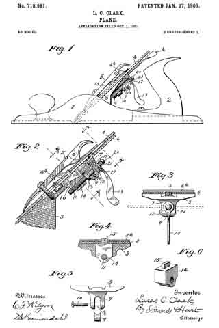
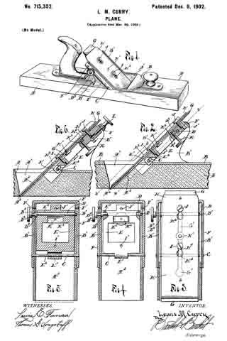
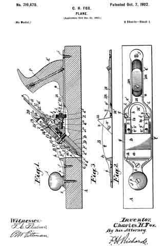
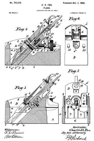
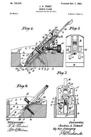
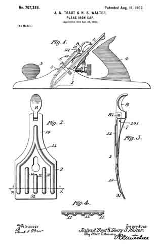
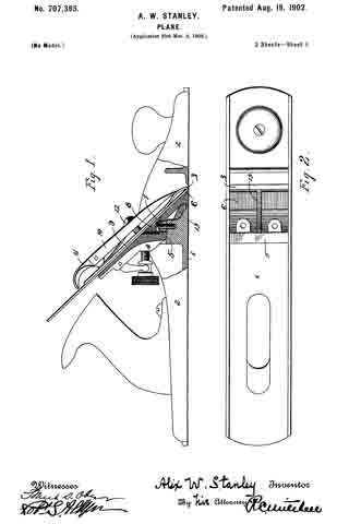
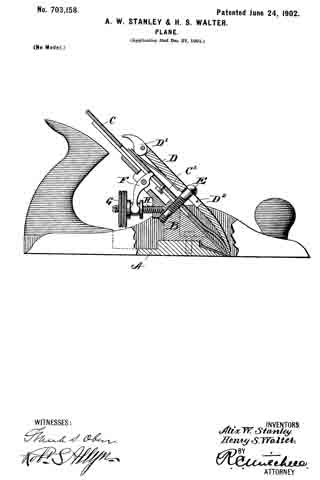
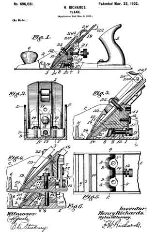
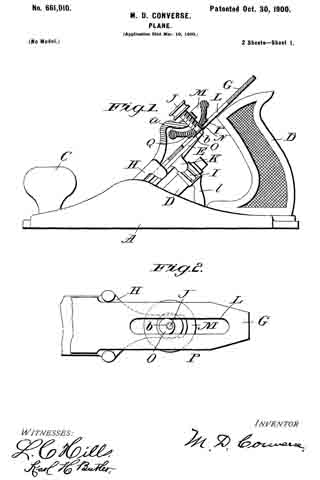
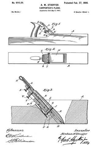
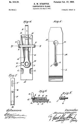
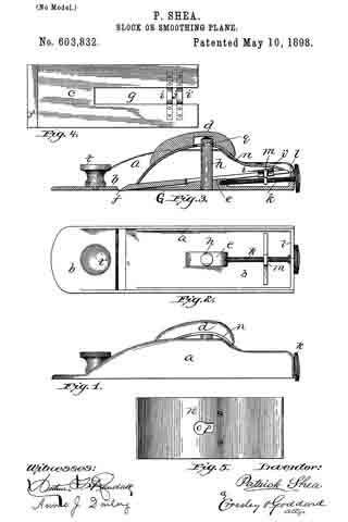
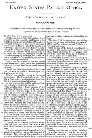
Figure 1 is a top plan view of my improved block-plane. Fig. 2 is a side elevation. Fig. 3 is a longitudinal mid-sectional elevation. Fig. 4 is a cross-sectional elevation.

In the specification similar reference letters indicate corresponding parts.

The metallic base or frame consists of the following structural parts: A is the base, from which rises two sides B B, that are joined by transverse ribs D and G. The former rib lies immediately in front of the opening E, through which the cutting edge of the blade J projects, and the rib G forms a support for said blade in the rear part of the frame and whereby the said blade is supported in a proper inclined plane. This inclined plane is a very essential feature of the invention, and to be more specific in describing it it is stated that the angle thereof is approximately not more than twelve degrees. With the cutting-blade held rigidly in such position by the means hereinafter described the work of the plane is rendered comparatively easy and effective.

C designates an integral projection rising from the front portion of the base A and upon which the index-finger of the operator rests.

F is a projection formed integral with the base and projecting beyond the rear end of the base. The object of this projection is to provide a suitable surface to be struck by a hammer or other implement in detaching the blade.

The sides B of the frame are provided on their outer surfaces with suitable grooves A”, which enable a suitable grip of the fingers in operating the plane.

That portion of the base A immediately in the rear of the blade-opening A is provided with a tapering surface A’ of a proper inclination to enable the blade to lie thereon at the angle hereinbefore specified.

H designates a round bar extending between the middle parts of the two sides B B and being rigidly secured in said sides, the position of such bar being substantially as indicated in the drawings.

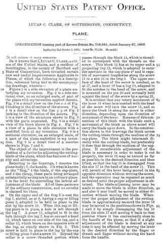
I designates a combined grip and wedge block, preferably constructed of wood and having a specially-formed slot in the front portion thereof, which extends and terminates rearwardly on an angle, substantially as shown. In a more specific description of this feature K’ designates the beginning or forward end of this slot, which, it will be observed, commences in an upright manner from the lower or straight surface of the block and gradually curving and extending in an upward and rearward inclination K. This slot extends through the block from one side to the other and receives the cross-bar H. By means of said slot the wedge-block may be rigidly forced in contact with the upper surface of the cutting-blade by pressing said block forwardly after said slot enters the bar H. The lower surface of said block, it will be observed, is made flat to snugly fit against the blade. When the block is forced by the hand of the operator to the position shown in the drawings, Figs. 2 and 3, the cutting-blade J is very firmly held against the transverse rib G. The act of operating the plane will tend constantly to increase this wedge-like contact between said block and the blade, as it will be seen that the pressure exerted by the hand upon the block in operating the plane is in a forward direction or a direction to force the cross-bar H farther up and into the slot.

Having described my invention, I claim —

In a block-plane, a frame having upright sides with intervening cross-ribs one of which supports the blade, a cross-bar between the upper portions of said upright sides and rigidly connected thereto, in combination with a combined wedge and grip block having a slot therein adapted to receive said cross-bar, said slot extending from the lower face of said combined grip and wedge block in a vertical direction and terminating in a rearward and upward inclination, whereby the pressure exerted upon said block in the operations of the plane will tend to increase the rigidity of contact between said block and the blade, substantially as set forth.

In testimony whereof I affix my signature in presence of two witnesses.

JOHN P. VANCE.

Witnesses:
A. J. FIORINI,
CAROLYN M. THEOBALD.

No. 718,981 – Plane (Lucas C. Clark) (1903)

[paiddownloads id=”579″]718981


UNITED STATES PATENT OFFICE.

_________________

LUCAS C. CLARK, OF SOUTHINGTON, CONNECTICUT.

PLANE.

_________________

SPECIFICATION forming part of Letters Patent No. 718,981, dated January 27, 1903.
Application filed October 1, 1901. Serial No. 77,188. (No model.)

_________________

To all whom it may concern:

Be it known that I, LUCAS C. CLARK, a citizen of the United States, and a resident of Southington, in the county of Hartford and State of Connecticut, have invented certain new and useful Improvements Applicable to Planes, of which the following is a description, reference being had to the accompanying draivings, wherein —

Figure 1 is a side elevation of a plane embodying my invention. Fig. 2 is a side sectional view, on an enlarged scale, of part of the plane with my invention applied thereto. Fig. 3 is a detail view on the line x x of Fig. 2 looking in the direction of the arrows. Fig. 4 is a detail view on the line y y of Fig. 2 looking in the direction of the arrows. Fig. 5 is a view of the structure shown in Fig. 3 with the parts separated. Fig. 6 is a detail view of the block shown in Fig. 4. Fig. 7 is a view of a plane in side elevation with a modified form of my invention. Fig. 8 is a sectional elevation, on an enlarged scale, of a part of the plane embodied in my invention. Fig. 9 is a detail view of a member shown in Figs. 7 and 8.

The object of the improvement is the production of a device for adjusting the cutting-blade of the plane, which has features of novelty and advantage.

Referring to the drawings, 1 denotes the plane-body; 2, the handle. 3 is what is known as the “frog,” at the blade, 4a the cap-plate, and 5 the clamp, these parts being arranged substantially as they are in an ordinary plane. 6 is the lever for controlling the lateral adjustment of the blade. All of these parts are of the ordinary construction, and no novelty is claimed for them.

On the upper end of the frog 3 is cast the lug 7, slotted, as at 8, having a cap or filling piece 9, adapted to be held in place in the slot by the screw 10. When this cap or filing piece is in place, a hole is left through the lug 7. A screw 11, adapted to fit in the hole through the lug 7, has at one end a head 12, which bears on one side of the lug, and a collar 13, which bears on the opposite side of the lug, as clearly shown in Fig. 2. This screw is held in place in the lug by the cap or filling piece 9 and a screw 10. Beyond the collar is a screw- threaded portion which passes through the block 14, which is threaded to correspond with the threads on the screw. This block 14 has at its upper end a projecting lug 15, which is adapted to enter the aperture in the cap-plate 4a and is capable of movement lengthwise along the screw 11 in a slot 16 in the frog 3. The upper surface of the head of the screw is notched, as at 17, and a lever 18 has a lug 19, adapted to fit the notches in the head of the screw, and is mounted on the pin 20 and normally held against the head of the screw by a spring 21.

It is evident that any rotary movement of the lever 18 when intermeshed with the head of the screw will turn the screw 11, and so move the block 14 along the screw in either direction, depending upon the direction of movement of the lever. Because of this connection of this block with the blade such a movement of the block as above noted will carry the blade up or down. In the constructlon shown in the drawings the block moves the cutting-blade through the medium of the cap-plate. The block might intermesh directly with the cutting-blade, but preferably it does that through the medium of the cap-plate. If considerable adjustment of the blade is necessary in order to make it cut properly, the lever 18 may be turned as far as possible in the desired direction and then lifted, so that the lug 19 is disengaged from the slot 17 in the head of the screw 11. This will permit of the lever being moved in the opposite direction without moving the screw, and the operation may be repeated as much as desired until the proper adjustment is obtained. The blade-adjusting lever may be made to move the blade in either direction, and also it may itself be moved in either direction without moving the blade. Whenever the proper adjustment of the cutting-blade is approximately secured the lever 18 may be moved to the positions shown in Figs. 1 and 2 by simply disengaging the lug 19 from the slots 17 and moving it back to that position where it lies conveniently close to the handle of the plane, so that if a slight adjustment of the blade is desired at any time it may be effected by moving the lever in the desired direction by the finger or thumb and finger without moving the hand from the handle.

It is well known that heretofore the adjustment of the blade up and down has been accomplished by a lever, one end of which engages the blade and the other end of which is bifurcated and straddles a screw, which is turned by a thumb-nut. This well-known mechanism has decided disadvantages. For instance, the size of the head of the screw must be small, because of the small space allowed for it, and the pitch of the thread of the screw is such that it is very ditiicult to turn the screw with such a small head. Again, there is enough backlash in the old construction to cause considerable difficulty in obtaining an accurate adjustment of the adjusting device and cutting-blade. By the use of the lever in my device I have what is equivalent, in the plane illustrated in the drawings, of a four-inch wheel, with which to turn my adjusting-screw. This permits me to use a screw of such a pitch that the backlash is practically nothing. Another decided advantage which my arrangement has over the well-known screw is that the blade may be adjusted vertically without removing the hand from the handle, and a slight adjustment may be obtained by simply moving the lever by the thumb or finger in the desired direction. In the ordinary adjustment, which has been referred to above, it is necessary to remove the hand entirely from the handle in order to operate the screw, such an arrangement being not nearly as advantageous as mine.

In Figs. 7, 3, and 9 I have shown a modification in which the block 14 is not threaded, the screw 11 being threaded intoa lug 22 on the frog. The operation ot the device is substantially the same as that shown in the first six figures, with the exception that here the screw moves, while in the perferred form the screw is stationary as far as lengthwise movement is concerned.

I claim as my improvement —

1. In a plane, the combination with the cutting-blade, of a frog provided on its rear face with an apertured lug, an adjusting-screw mounted in the aperture of the said lug, a transversely-arranged screw in the said lug for securing the said adjusting-screw in position, a blade-adjusting block extending to the rear of the frog and in engagement with the said screw and secured at its forward end to the said blade, and means for rotating the said screw.

2. In a plane, the combination with the cutting-blade, of a frog rigidly secured in the plane and provided in its upper portion with a longitudinally-arranged slot, a lug formed integral with the said frog, said lug having a longitudinal slot, the rear side of which is open, an apertured block arranged in the said longitudinal slot, a screw extending through the openings in the said lug and block and means for rotating the said screw.

3. In a plane, the combination with the blade, of a frog having its upper end reduced in thickness and provided with an elongated slot therein, a lug formed integral with the said frog and provided with a longitudinal aperture extending inward from the rear side of the lug, a block slidably mounted in the slot of the frog, and having its inner end secured to the blade, an adjusting-screw mounted in the said lug and being in screw-threaded engagement with the said block, a transversely-arranged screw secured in the said lug, and a cap on the said screw, substantially as and for the purpose specified.

4. In a plane, the combination with the blade, of a frog provided in its upper end with an elongated slot, a block slidably mounted in the said slot and having its inner end secured to the blade, a lug formed integral with the said frog and provided with a longitudinal slot, an adjusting-screw having its lower end in screw-threaded engagement with the said block, and its upper end arranged in the aperture of the said lug, a head formed integral with the said screw and bearing on the lower face of the said lug, a collar formed integral with the screw and bearing on the upper face of the said lug, and means for adjusting the said screw.

5. In a plane the combination of a cutting-blade, an adjusting-screw provided with a notched head, means carried by said screw and engaging the blade, whereby the rotation ofthe screw adjusts the blade longitudinally, and a lever rotatably mounted on said screw and extending radially therefrom, said lever being free to tilt thereon to engage and disengage therewith to rotate it, substantially as described.

6. In a plane, the combination of a cutting-blade, an adjusting-screw provided with a notched head, means carried by said screw and engaging the blade whereby the rotation of the screw adjusts the screw longitudinally, a lever rotatably mounted on said screw and extending radially therefrom, and being free to tilt thereon to engage and disengage therewith to rotate it, and a spring to normally hold the lever in engagement with the screw.

7. In a plane the combination of the cutting-blade, the adjusting-screw having a notched head, means actuated by the said screw for adjusting the said blade, an adjusting-lever mounted on said screw and adapted to engage or be disengaged from the notched head of the said screw, said lever being adapted and located to be operated by the hand of the operator grasping the handle of the plane, and a spring to normally hold the lever in engagement with the said screw.

LUCAS C. CLARK.

Witnesses:
W. E SIMONDS,
D. C. KREIMENDAHL.

No. 716,386 – Plane (Maschil D. Converse) (1902)

[paiddownloads id=”576″]716386


UNITED STATES PATENT OFFICE.

_________________

MASCHIL D. CONVERSE, OF NEW YORK, N. Y., ASSIGNOR TO
JOHN J. TOWER, OF MONTCLAIR, NEW JERSEY.

PLANE.

_________________

SPECIFICATION forming part of Letters Patent No. 716,386, dated December 23, 1902.
Application filed October 29, 1901. Serial No. 80,470. (No model.)

_________________

To all whom it may concern:

Be it known that I, MASCHIL D. CONVERSE, a citizen of the United States, residing at New York, borough of Manhattan, in the county and State of New York, have invented new and useful Improvements in Planes, of which the following is a specification.

My invention relates to improvements in planes, and more particularly to means for securing and adjusting the irons thereof; and the objects of my invention are to improve the efficiency of such and to simplify the construction and reduce the cost of manufacture.

My invention is comprised in certain novel mechanisms, construction, arrangement, and combinations of parts hereinafter fully set forth and claimed.

In the drawings, Figure 1 is a longitudinal vertical sectional elevation of a plane, of a type commonly known as “iron corrugated-bottom” planes, showing my invention incor-porated. Fig. 2 is a plan view of important parts of my invention, compassing the principal means for accomplishing vertical adjustment of the plane-iron. Fig. 3 is a plan view of the plane-iron and lateral-adjustment mechanism. Fig. 4 is a cross-section on line x x of Fig. 1; and Figs. 5 and 6 are views, partly sectional, illustratrating modilied constructions of my invention, all showing construction, application, and operation of my invention, as will be hereinafter more fully set forth in detail.

My invention may be applied to all types of planes, although I have shown it as applied to iron planes, as hereinbefore stated.

Planes have been made with mechanisms for vertical adjustment of the irons comprising bell-crank members and transverse grooves in the plane-irons to be engaged thereby pivoted to the body. Others have been made with mechanisms for vertical adjustment of the irons comprising bell-crank members and transverse slots in the plane-irons to be engaged thereby and pivoted to the body above the fulcrum-screw, and still others have been made with mechanisms for vertical adjustment of the irons comprising bell-crank members pivoted through the longitudinal slot of the plane-iron to a bed-piece at points above the fulcrum-screw and in engagement with notches in the cap-plate. Planes of such construction are expensive of manufacture, involving careful and accurate dimensioning of the throat and finishing of the ways and channels by difficult and tedious machining. In my present invention I overcome these disadvantages by novel arrangement and form of parts, dispensing entirely with the notches in the cap-plate and with the transverse grooves or slots in the plane-irons, rendering it wholly unnecessary to perform any expensive machining or fitting to compass a proper and accurate adjustment and holding of the plane-irons, all of which will be clearly seen and understood by those skilled in the art from the descriptions following.

Like letters indicate corresponding parts throughout the several figures.

A is the body of the plane, B a knob attached to the front portion thereof, and C the handle proper attached to the rearward portion.

D is a post and saddle-rest, which in case of iron-body planes is preferably cast integral centrally thereof. The apex of this post l prefer to make A-shaped, (distinctly shown at a, particularly in Fig. 4,) and the face thereof sloped to correspond with the incline b at its forward and broadened base c, the latter forming pivotal points and a rest for the extreme lower end of a vertical-adjustment lever d, which is pivoted thereto by a screw e. Upon the flattened upper surface of the pivoted end of the lever d rests the lower end of a flat saddle-plate f, which lower end is slotted longitudinally and recessed or countersunk on the upper side at g to receive the said pivot-screw e, which also serves to hold it in place, though admitting of a vertical sliding movement. Adjacent to the upper end of this saddle on the nether side a projection i is cast or formed, and a V-shaped groove h is formed therein to rest in slidable engagement with the sloping A-shaped apex a of the post D, which also serves to retain the same against lateral movement, a condition necessary for the carrying out of part of my invention. At a point centrally thereof and between the V-grooved projection i and above the slot g and pivot e is another opening in the saddle at j, the narrower lowermost end of which is recessed or countersunk on the under side at k to receive the head of the fulcrum screw or stud l when the same is slipped under the laterally-overhanging edges thereof. This fulcrum screw or stud l is secured in a clamping-plate m from its under side, (and I prefer to use a screw for convenience of adjustment.) In the upper end of the clamp-plate is a gnarled-head cramp-screw n, the rounded end of which engages a depression o of a lateral-adjustment lever p, serving as a pivot therefor. The vertical-adjustment lever d is provided at its upper end with a button q for operating. Midway of the ends and laterally of the slot g in the saddle f there is a hole r (see Fig. 2) for reception of a stud s, (freely fitting it, see same figure,) which stud is fixed (preferably rigidly) upon or in the vertical-adjustment lever d at a like position laterally relatively the axis thereof and pivot-screw e. This stud s and the hole r are located on a transverse line at right angles to the longitudinal vertical centers of the lever d and sliding saddle f, respectively, directly opposite the center of the pivot-screw e and sufficiently distant therefrom that it may not bind by describing an arc of too small a radius when the lever is operated.

For convenience and so that post D and projection i may not interfere therewith the lever d is open or divided at u and joined again above at the button q.

T is the plane iron or bit, which has a slot t longitudinally its center to admit of passage of the head and shank of the fulcrum-screw l therethrough.

In the modifications shown by Figs. 5 and 6 the principles of my invention hold, these modifications being such as render my invention applicable to what are known as “block-planes.” In the case of Fig. 5 the cramp-screw n5 is inverted and screw~socketed within and on the under side of the shell-like extension of the clamp-plate m5. The gnarled head of the screw being enlarged somewhat is accessible from the lateral sides, while in the case of Fig. 6 instead of a cramp-screw a projecting point n6 serves to engage the lateral-adjustment lever p6 as its pivot, and a gnarled head cramp-screw l6 is entered from the forward upper side through the clamp-plate m6 and engages a threaded hole k6 in the saddle f6.

The operation of my invention is as follows: To raise or lower the plane-iron T, push the button q to the left or right hand, which will cause the stud s to carry the saddle f up or down as the lever is rocked on its axis at e. To square the cutting end of the plane iron or bit with the throat of the plane, push the lever p to the right or left, as may be required, which causes the eccentric v to move the bit till the desired lateral adjustment is had. All these movements may be made without loosening the cramp-screw.

I do not limit myself to the specific form of the vertical-adjustment lever described herein, except that it should be located beneath the saddle f, which rests upon its lower end, and have its pivotal axis e and saddle-engaging stud s at its lowermost end or below the transverse plane of the fulcrum-screw and the apex of the post D, nor do I limit myself to the particular form of the post or of the saddle herein described, as manifestly they may be modified without departing from the spirit of my invention.

It will be readily understood by those skilled in the art that the novel construction and arrangement of the parts in my present invention, as well as their simplicity, make it possible to cast the same in metal to substantially finished form and dimensions, excepting the screws, thus saving the laborand cost of fitting.

I do not herein claim the lateral-adjustment mechanism shown, except in combination with the leading features of my present invention, for the reason that the same was allowed to me broadly by Letters Patent of the United States No. 619,394, dated February 14, 1899; but,

Having described my invention, what I do claim as new, and desire to secure by Letters Patent, is —

1. In a plane a vertical-adjustment mechanism comprising a laterally-movable lever pivoted centrally to the plane-body at a point below the transverse plane of the fulcrum-screw and of the apex of the post; a stud located thereon on the top side and laterally opposite its axis, a saddle engaged by said stud held in place by the pivot-screw of said lever, and slidably resting upon the pivoted end of the same and upon the apex of a post above said fulcrum-screw, in combination with a plane-iron and means for clamping the latter upon said saddle.

2. In a plane a laterally-movable lever pivoted centrally to the plane-body at a point below the transverse plane of the fulcrum-screw and of the apex of the post; a stud located thereon on the outer side and laterally opposite its axis; a saddle engaged by said stud held in place by the pivot-screw of said lever and slidably resting upon the pivoted end of the same and upon the apex of a post, above said fulcrum-screw; a plane-iron and means for clamping the same upon said saddle, in combination with mechanism for lateral adjustment of the plane-irons.

3. In a plane a vertical-adjustment mechanism comprising a laterally-movable lever pivoted centrally to the plane-body at a point below the transverse plane of the fulcrum-screw and of the apex of the post; a saddle slidably resting upon the pivoted end of said lever and upon the apex of a post; a laterally-located stud operatively connecting said saddle and said lever below the transverse plane of the fulcrum-screw, and a plane-iron, in combination with a lateral-adjustment lever eccentrically pivoted at the upper end of a clamp-plate.

4. In a plane a vertical-adjustment mechanism comprising a laterally-movable lever pivoted at its lower end; a saddle slidably resting upon the pivoted end of said lever and upon the apex of a post removed from the pivoted end of said lever, in combination with means for operatively connecting said lever and said saddle at their respective lower ends to accomplish vertical movement of the latter.

5. In a plane a laterally-movable pivoted vertical-adjustment lever, having an opening u centrally thereof, in combination with a saddle operatively engaged by said lever and having a groove h longitudinally central thereof on its under side contacting with the apex of a central post D within the plane-body and held in place by the pivotal screw of the lever.

6. In a plane a laterally-movable pivoted vertical-adjustment lever, having an opening fa centrally thereof, in combination with a post D projecting within said opening.

MASCHIL D. CONVERSE.

Witnesses:
WARREN W. WHITNEY,
J. MEACH.

No. 715,352 – Plane (Lewis M. Curry) (1902)

[paiddownloads id=”575″]715352


UNITED STATES PATENT OFFICE.

_________________

LEWIS M. CURRY, OF BRIGHTON , MICHIGAN.

PLANE.

_________________

SPECIFICATION forming part of Letters Patent No. 715,352, dated December 9, 1902.
Application filed March 29, 1902. Serial No. 100,512. (No model.)

_________________

To all whom it may concern:

Be it known that I, LEWIS M. CURRY, a citizen of the United States of America, residing at Brighton, in the county of Livingston and State of Michigan, have invented certain new and useful Improvements in Planes, of which the following is a specification, reference being had therein to the accompanying drawings.

My invention relates to improvements in carpenters’ planes; and its object is to provide a cheap and simple construction which is strong and durable, having few parts, easily assembled, and not liable to get out of order, and to provide ready means for accurately adjusting the plane-bit longitudinally within the throat and to so construct the parts as to allow for a slight lateral adjustment of the bit, it also being the object of this invention to provide means for clamping the bit and its shavings-breaker to the support therefor, so that they are firmly held without the necessity of a clamping-plate or other obstruction on the upper side of the breaker, and the bit will be frictionally held against accidental lateral movement thereby, but may be so adjusted by the operator.

To this end the invention consists in providing a longitudinally-movable carrier for the bit, which carrier is supported at an inclination substantially the same as that of the bed and free to move laterally on its support, and in providing suitable means for securing the bit to the carrier at one end, which means also serves to hold the lower end of the bit in strong frictional contact with the bed to prevent such lateral movement of the bit except when adjusted by the operator; and the invention further consists in providing suitable mechanism for moving the carrier and attached bit longitudinally to regulate the cut, and also in the particular construction, arrangement, and combination of parts, all as more fully hereinafter described, reference being had to the accompanying drawings, in which —

Figure l is a perspective view of a device embodying my invention; Fig. 2, a longitudinal vertical section through the bit and adjacent parts and a portion of the stock on the line 2 2 of Fig. 3. Fig. 3 is a section on the 2, showing a plan view of the line 3 3 of Fig. 2; Fig. 4, a section on the line 4 4 of Fig. 2, showing the carrier in plan; Fig. 5, the same, showing the carrier in section and illustrating the manner in which the bit is adjusted laterally; and Fig. 6 is a longitudinal vertical section similar to Fig. 2, showing a modified adjustment for the carrier and showing the bit unclamped to illustrate the manner in which it is held against the bed.

A is the stock of the plane, formed, in the usual manner, of hard wood, with a throat A’, having the mouth A2, and one side extended at an inclination of about forty-five degrees to form the bed A3, upon which the bit-iron or knife rests.

B is a casting secured to the top of the stock and provided with upwardly-extended supporting flanges or sides B’, which form bearings for the transverse pin C and eccentric-rod D, which support the bit-carrier E. Said carrier E consists of a rectangular casting having its middle portion cut away to lighten the same and provided with a lug E’, projecting from its lower end, which lug has an elongated opening E2 or slot through which the pin C extends, and through a transverse opening E3, near its upper end, extends the eccentric-rod D, which rod is provided with bearing ends D’ and D2 to engage the bearings in said sides B’. The rod D is set eccentrically to its bearing ends, so that when the same is turned by the knurled head D3, which is secured on the outer end of the reduced portion D4, the carrier will be moved a distance equal to the throw of said eccentric, and to secure the eccentric in place and connect the sides B’ a yoke F is provided, which embraces the sides B’ and is secured at its lower ends by the pin C, which extends therethrough and is riveted at its outer ends and near the top of the sides by the screws F’, said yoke extending over and closing the outer end of the opening forming the bearing for the end D’ of the eccentric and has an opening to at the reduced portion D4, thus securing the eccentric in place and forming a brace for the sides B’.

The knife or bit-iron G and its cap-iron or shavings-breaker H are secured together in the usual manner by a set-screw H’ engaging a slot G’ in the bit. The breaker is nearly as long as the bit and is provided with openings H2, having lateral extensions H3, located opposite the slot G’, to receive the heads of the screws I and J, which screws engage screw-threaded openings I’ and J’ in the carrier E, the head of the screw I forming an abutment to engage the upper side of the breaker.

The carrier E is supported at substantially the same inclination as the inclination of the bed A3, and the screw I is adjusted to bring its head at such a height relative to the bed that when said head is passed through the openings H2 and the breaker moved to engage the extension H3 with the shank of the screw the lower end of the bit will engage the bed adjacent to the mouth.

A binding-screw K engages a screw-threaded opening K’ in the carrier E, and on the inner end of said screw is a head K2, a recess K3 being provided in said carrier for said head, which head is forced upward by the turning of the screw into engagement with the under side of the bit and forces the lower end of the bit against the bed, the screw J being properly adjusted relative to the screw I to form a stop to prevent the bit from being bent too far by the action of the screw. The turning of the binding-screw K thus not only secures the bit to the carrier, but forces the same into frictional contact with the bed by the spring of the said bit, and by adjusting the screws I and J the frictional contact may be increased or diminished and the angle of the bit changed, so that it will lie flat upon the bed or will contact the same only at its lower end.

The carrier is made somewhat narrower than the space between the sides B’, and the eccentric is made to have a little play in its bearings, so that said carrier may be shifted laterally. When the bit is in place, the frictional contact thereof with the bed will hold the lower end of the bit so that when the upper end of the carrier is shifted the bit will be tilted to bring its cutting edge even with the sole of the stock when the bit is not ground exactly true, as shown in Fig. 5, and the spring action of the bit and its breaker causes a friction on the eccentric D, so that it will not be accidentally turned.

If desired, an adjusting-screw L, passing through an opening in the yoke F and engaging screw-threaded openings in the carrier, may be provided to move the carrier instead of the eccentric D; but I prefer said eccentric, as it is more accurate, is simple, cheap, and more durable.

Having thus fully described my invention, what I claim is —

1. In a plane, the combination with the stock; of side flanges on said stock, a bit, a movable carrier to which the bit is secured, and means supported by said flanges for supporting and moving the carrier to adjust the bit.

2. In a plane, the combination with the stock; of side flanges on said stock, a laterally-movable bit-carrier, a bit secured to said carrier, and means on the flanges for supporting the carrier and upon which it may be moved laterally of the stock to tilt the bit.

3. In a plane, the combination with the stock; of side flanges on said stock, a bit-carrier supported by said flanges and adapted to be moved laterally between the same, a bit on said carrier, and means for securing said bit to the carrier and for causing a frictional resistance to such lateral movement of the carrier.

4. In a plane, the combination with the stock; of a bit adapted to be moved longitudinally, side flanges on said stock and an eccentric supported by said flanges and adapted to move said bit.

5. In a plane, the combination with the stock thereof having a bed; of a carrier supported upon said stock and provided with screw-threaded openings a bit having an opening and engaging said bed at one end, a screw engaging one of the openings in the carrier and projecting through said opening in the bit to engage its head with the upper side of said bit, and a binding-screw engaging the other opening in the carrier and contacting the under side of said bit.

6. In a plane, the combination with the stock and a bit thereof; of supporting-flanges on said stock, a carrier to which the bit is secured, supported by said flanges to move longitudinally and provided with a transverse opening, and an eccentric within said opening.

7. In a plane, the combination with the stock thereof; of supporting-flanges on said stock, a carrier having a slot and a transverse opening, a pin supported by the flanges and engaging said slot, a rod in said opening having eccentric ends engaging bearings in said flanges, a bit, and means for securing said bit to said carrier.

8. In a plane, in combination a stock having a bed, supporting-flanges on said stock, a carrier having a slot at its lower end and a transverse opening near its upper end and screw-threaded openings, a pin secured at its ends to the supporting-flanges and extended through said slot, a rod in the transverse opening and having eccentric ends engaging bearings in the flanges, and provided with a head, a bit having openings, screws having heads projecting through said openings and engaging the upper side of the bit and adjustable in the screw-threaded openings in the carrier, a binding-screw extending through said carrier and a head on said binding-screw engaging said bit.

9. In a plane, the combination of a stock a casing secured to the upper side of said stock, the supporting-flanges on said casings having openings, a longitudinaily-movable carrier having a slot and a transverse opening, a pin extending through the opening in the flanges and the slot in the carrier, a rod engaging the transverse opening in the carrier and provided with eccentric ends engaging bearings in said flanges and having a reduced portion provided with a knurled head, a yoke embracing the flanges and provided with an opening to receive the reduced portion of the eccentric, and a bit secured to said carrier.

In testimony whereof I affix my signature in presence of two witnesses.

LEWIS M. CURRY.

Witnesses:
LEWIS E. FLANDERS,
OTTO F. BARTHEL.

No. 710,678 – Plane (Charles H. Fox) (1902)

[paiddownloads id=”574″]710678


UNITED STATES PATENT OFFICE.

_________________

CHARLES H. FOX, OF NEW BRITAIN, CONNECTICUT, ASSIGNOR TO
THE STANLEY RULE & LEVEL COMPANY, OF NEW BRITAIN, CONNECTICUT,
A CORPORATION OF CONNECTICUT.

PLANE.

_________________

SPECIFICATION forming part of Letters Patent No. 710,678, dated October 7, 1902.
Application filed December 31, 1901. Serial No. 87,942. (No model.)

_________________

To all whom it may concern:

Be it known that I, CHARLES H. FOX, a citizen of the United States, residing in New Britain, in the county of Hartford and State of Connecticut, have invented certain new and useful Improvements in Planes, of which the following is a specification.

This invention relates to bench-planes; and it consists, substantially, in the improvements hereinafter more particularly described.

Without attempting to enumerate the advantages of the present invention by comparison with other planes hitherto devised it may be stated that the present invention has for its object to provide a plane of simple and effective construction and organization and one in which the plane mechanism is economically and compactly seated in place upon the stock in such manner as to overcome or prevent any tendency to chattering ot the operative portion of the plane-iron, and also to provide an extended bearing for the rear or under side of the supporting-frame of the plane mechanism, and to greatly strengthen the fastening for such frame without materially adding to the weight of the plane.

A further object is to provide means for preventing dislodgment or disorganization of the plane mechanism either in part or in entirety due to any tendency thereof to rise from its seat upon the stock, from drag upon the plane-iron, or from other causes.

A still further object of the invention is to provide means for fastening the supporting-frame to the stock in the most. rigid and secure manner, while readily permitting vertical or up and down adjustments of such frame for the purpose of effecting changes in the position of a wearing-sole in conformity with the needs thereof, and also to provide means whereby the up and down adjusting devices for the plane-iron are housed in part and protected against accidental displacement in the use of the plane.

The above and additional objects are attained by means substantially such as are illustrated in the accompanying drawings, wherein —

Figure 1 is a longitudinal sectional elevation of a plane embodying my improvements, said view being taken just to one side of the median line of the width of the stock, several of the parts being shown in elevation. Fig. 2 is a top or plan view thereof with the plane mechanism removed. Fig. 3 is a central longitudinal sectional view of the top iron of the plane. Fig. 4 is an enlarged view similar to Fig. 1 to more clearly indicate the construction and organization of parts or elements comprising or constituting the plane mechanism, the stock or body of the plane being broken off at each end. Fig. 5 is also a similar view taken to one side of the median line of the width of the stock and just to the outer side of one of the fastening-screws for the frame of the plane mechanism, so as to clearly show the construction and organization. Fig. 6 is a view looking at the rear or under side of the supporting-frame for the plane mechanism, said plate being minus any of such mechanism as well as the adjusting elements for the plane-iron; and Fig. 7 is a view looking at the front or upper side of the supporting-frame, the stock and top iron being shown in vertical section and the laterally-adjusting lever for the plane-iron being partly broken off.

Before proceeding with a more detailed description it may be stated that in the practice of my invention I provide the body or stock of the plane of any suitable wood, and I form therein from top to bottom an opening the surface of the rear wall of which is inclined to provide a seat of proper angle or inclination for the plane-iron mechanism and the surface of the front wall of which is specially constructed at the bottom of the stock to cooperate with the lower end of the frame of the plane mechanism, as and for the purpose hereinafter specifically explained. To provide an extended and continuous bearing-surface for the supporting-frame of the plane mechanism, I extend the rearwardly and upwardly inclined surface of the rear wall of the opening in the stock some distance above the top of the stock, and preferably such extension is in duplicate with the parts thereof on opposite sides of the median line of the width of the stock. The supporting-frame is provided separately with some suitable laterally and vertically adjusting devices for the plane-iron, and the said plane-stock and supporting-frame are so constructed that the principal parts of the said vertically-adjusting devices are snugly and conveniently housed in such manner as not to become broken or disarranged accidentally while the plane is in use, yet readily accessible for adjusting or changing the position of the plane-iron. Preferably the upward extensions of the surface of the rear wall of the opening in the stock are of metal, constituting integral parts of the plane-iron, and the supporting-frame of the plane mechanism is provided with a sole or wear plate receiving the wear of the plane and havinga throat for the play of the operative end of the plane-iron. The supporting-frame is also otherwise specially constructed at its lower end to cooperate with the said specially-constructed part of the surface of the front wall of the plane-opening to prevent uprising or dislodgment of said frame and the other parts of the plane mechanism supported or carried thereby, and preferably, also, the fastenings for the frame are introduced into the said duplicate metal extensions of the rear surface of the opening of the stock rather than in the stock itself. The construction enables use to be made of plane stocks or bodies of comparatively limited height and is otherwise especially advantageous, both from a commercial and practical point of view.

Specific reference being had to the accompanying drawings, wherein an embodiment of my invention is shown and which maybe the preferred embodiment, A represents the stock or body of the plane, constructed of any suitable wood for the purpose and formed therein at the proper point of its length with an opening a, the surface b of the rear wall of which is rearwardly and upwardly inclined at an angle of about forty-five degrees (45°) to the base of the plane, so as to give to the plane mechanism seated upon such surface the proper inclination within such opening. The lower corner of the front wall c of said opening a is also cut off or beveled to produce a similarly-inclined shorter surface d, which is preferably parallel with the said surface b, for the purpose hereinafter understood. In the top surface thereof the said plane stock or body is cut out or recessed a short distance centrally thereof, so as to provide a cavity e, leading rearwardly from the opening a and designed to partially receive the operating element of the up and down adjusting devices for the plane-iron in the manner shown and as hereinafter specifically set forth. Secured in place upon the upper portion of the stock or body by means of screws or similar fastenings f is the top iron B, which is constructed with parallel and slightly raised or elevated side portions g g, the inner surfaces of which may be practically flush or even with the corresponding surfaces of the sides of the opening a, already referred to. Said side portions g g are united by an integral rib h, connecting the same at about the upper forward edge of said opening a, and forwardly of said rib the said top iron is formed with a short longitudinal extension i, on which is seated the knob or forward handle j of the plane, said knob being held in place by a screw k, entering the stock through a suitable opening therefor in said forward extension. The rearward ends of the side portions g g of the top iron gradually decrease in height and slightly converge at l l, whence they terminate in parallel elevated flanges m m, formed on a rearward longitudinal extension n, and upon which latter, between said flanges, is seated the base o of the main or rear handle C of the plane, said handle being securely fastened in place by a screw-rod p, passing through the same and secured at its lower end in a threaded opening in the said extension n therefor. The forward part of said rearward extension it of the top iron is cut out or notched at n’, so as to bring the inner edges e’ thereof about even with the side and rearward edges of the recess or cavity e of the plane-stock, and thus are formed the integral flanges s s of the top iron, which are seated upon the upper surface of said stock on opposite sides of the said recess or cavity therein. Said flanges are each provided with a hole or opening for the passage of a screw t, which enters the stock on opposite sides of the median line of the width of the same, and thus is an extremely rigid and compact structure derived. Said side flanges s s of the top iron are each widened somewhat at s’, and they also constitute bases for preferably duplicate integral supports u u for the frame D of the plane mechanism E, said supports of course being also on opposite sides of the median line of the width of the plane and being integral at the outer sides thereof with the adjacent inner surfaces of the rear ends of the side portions g g of the top iron. In this way increased width or thickness of each of the said supports it is obtained for the formation therein of a threaded opening v for the reception of a screw w for securing the supporting-frame D in place and which construction does not materially add to the weight of the plane. The forward edges or faces x x of said supports u u are faced off in the same plane and at an upward and rearward inclination corresponding to the angle of inclination of the surface b of the rear wall of opening a in the stock, and thus said faces of the said supports constitute practical upward continuations or extensions of said surface b. In this way an increased, even, and continuous bearing-surface is obtained for the under side of the supporting-frame D of the plane mechanism, as is obvious. The frame D is substantially a rectangular plate the upper part d’ of which is comparatively thin, while the remaining lower portion thereof is of increased thickness, for the purpose hereinafter understood, although recessed or hollowed out, as at y y, on its upper surface, so as to lessen the weight thereof as much as possible without any less of strength. At its lower end the said supporting-frame is formed or provided with a sole d2, in which is formed transversely a throat d3 for the player working of the lower and operative end of the plane-iron F in a manner well known. Also formed with said frame and preferably on the upper part of said sole-plate forwardly of the throat therein is a wedge G, the forward surface of which is at a corresponding angle to the undercut or beveled portion d of the surface of the front wall of the said opening a in the stock. Formed on the under side of the frame D, about centrally thereof, is a pendent or hanging portion d5, having in its rear face a threaded opening in which works the inner end of an adjusting-screw d4, having thereon an operating-button d5, provided with collars 1 1, forming between them a circumferential groove 2, in which are received on opposite sides of said screw the ends of the furcated arm 3 of a swinging lever 4, having its bearing on a rod or pin 5 between short flanges 6 6, also formed on the under side of said frame, the end or nose of the shorter arm 7 of such lever protruding forwardly through an adjacent opening or slot 8 in the said frame, all as shown. The said elements constitute the usual or well-known vertical or up-and-down adjusting devices for the plane-iron F, and it will be seen that the same are brought to a comparatively low position with reference to the plane-stock, the operating-button d5 thereof extending partly into the cavity e of the stock, thus economizing greatly in the space consumed or occupied by said devices as a whole. Moreover, in virtue of the lower part of the frame D being of an increased thickness downwardly, beginning at a point somewhat below the point of suspension of the lever 4 thereon, said adjusting devices are thus carried forwardly a distance about equaling the difference of thickness between the two parts of said frame, and are thereby caused to be snugly housed in the space between the inclined extended bearings or supports u u. In this way the operation of the adjusting devices in question may be effected without difficulty, while at the same time they are prevented in large measure from breakage or disarrangement by contact with external objects in the handling of the plane. Above the opening or slot 8 in the upper part of frame D is a recess 9, in which works a button 10, carried on the end of the well-known form of laterally-adjusting lever 11 for the plane-iron pivoted at 12 on the frame, the said button engaging, as usual, the sides or edges of a longitudinal slot or opening 13 in said plane-iron. Screwing in to the said supporting frame or plate D ofthe frame mechanism, about centrally of the width thereof and at a point about corresponding to the upper surface of the plane-stock, is an upwardly and forwardly projecting screw 15, over which is fitted the plane-iron F, having secured thereto by means of screw 16 the ordinary top plate F2, and above the top plate and also fitting ever the screw by means of an opening or slot 17 therein is the usual clamping device or lever 18, with the edges of the said slot therein engaging under the head of said screw, the parts all being held together within the opening a of the stock by the clamping action of said clamping-lever 18 caused by the cam 19 when turned down against the top plate by means of its operating-lever 20, the said cam bearing directly upon a spring 21, secured on the under side of said clamping-lever and all operating in an obvious manner. Formed in the said supporting frame or plate D, on either side of the median line of the width thereof, are the slots er openings 25, the lower edge of each of which is substantially in the plane of the longer axis of screw 15, and the length of each of which is only suflicient for maximum vertical or up-and-down adjustments of the frame, whereby the sole d2 at the lower end thereof may be carried to any extent of protrusion beyond the under or wearing surface of the stock by which to practically receive and sustain the greater part of the wear of the plane in use. Said slots or openings 25 are also in direct line with the screw-holes v v in the extensions or supports u u, the original position of such openings prior to any adjustment of the frame being about midway the length of the slots, substantially as shown in Figs. 4 and 5, and the frame is chamfered or countersunk at 27 around the edges of said slots, so as to bring the heads of the fastening-screws w for the frame at least flush with or below the upper surface of the latter, and thereby enabling an even seating of the plane-iron upon said frame. From the construction and organization shown and described it will be seen that the fastening-screws w for the frame D are brought into the nearest practical proximity or relationship with the said forwardly-projecting screw 15, and thus is there partially established a counterbalance between the opposing forces acting separately on said screw 15 and the screws w, the one force tending to pull the frame outwardly or upwardly and the other tending to hold the frame (and consequently the entire frame mechanism) down upon its seat or bearing upon the stock within the opening a therein. Inasmuch, however, as the pressure or force exerted by cam 19 as well as that exerted by screws w are both on the same side of and above screw 15, which latter it will be understood is a fulcrum for the clamping bow or lever 18, there is a slight tendency to uprising of the lower end of the frame D, which tendency is successfully or effectually resisted by the forward inclined face of the wedge G firmly abutting or engaging the opposing inclined surface d of the lower part of the front wall of the said opening a, in the stock. In this way there is established a most perfect counterbalance or equilibrium of the forces acting upon the parts of the planes in different or opposing directions, thereby overcoming or preventing any tendency to vibration or chattering of the plane-iron irrespective of the degree of hardness of the wood upon which the plane is used.

It will be seen from the foregoing description, taken in connection with the accompanying illustrations, that I have provided a bench-plane possessing compactness and stability and one in which adjustments may be made readily and accurately without loss of time. The plane is strong and capable of withstanding all the handling incident to the conditions under which the same may be used, and the general commercial as well as practical advantages thereof will be apparent without further mention. It will be understood, of course, that I do not limit myself to the precise details of construction and organization of the elements of the plane, since changes may be made therein without departing from the spirit and scope of my invention.

Having described my invention, I claim —

l. A plane-stock with an opening therein having duplicate upward extensions of the surface of the rear wall thereof, such surface being of the same alinement throughout and the extensions thereof directly continuous therewith, a supporting-plate for a plane-iron seated within the opening, and fastenings for said plate entering said surface extensions.

2. A plane-stock with an opening therein the surface of the rear wall of which is rearwardly and upwardly inclined and provided with duplicate upward extensions thereof, such surface being of the same alinement throughout and the extensions thereof directly continuous therewith, a supporting-plate for a plane-iron seated within the opening, and fastenings for said plate entering said surface extensions.

3. A plane-stock with an opening therein the surface of the rear wall of which is rearwardly and upwardly inclined and provided on opposite sides of the median line of the width of the stock with duplicate upward extensions thereof, such surface being of the same alinement throughout and the extensions thereof directly continuous therewith, a supporting-plate for a plane-iron seated within the opening, and fastenings for said plate entering said surface extensions.

4. A plane-stock with an opening therein the surface of the rear wall of which is rearwardly and upwardly inclined and of the same alinement throughout, and a top iron secured to the stock and formed with duplicate directly-continuous extensions of such surface, a supporting-plate for a plane-iron seated within the opening, and fastenings for said plate entering said surface extensions.

5. A plane-stock having therein an opening the surface of the rear wall of which is rearwardly and upwardly-inclined and of the same alinement throughout, and the lower part of the front wall of which is undercut in parallelism therewith, said stock being provided with a top iron having duplicate directly-continuous extensions of such rear-wall surface, a supporting-plate for a plane-iron seated within the opening, and fastenings for said plate entering said surface extensions.

6. A plane comprising a stock having an opening therein the surface of the rear wall of which is rearwardly and upwardly inclined and of the same alinement throughout, a top iron having directly-continuous duplicate extensions of such surface located on opposite sides of the median line of the width of the plane, a plane mechanism having vertically-adjusting devices for the plane-iron housed between the extensions, and means securing the supporting member of said plane mechanism to the faces of said extensions, said means entering said extensions at the said faces thereof.

7. A plane comprising a stock having an opening therein the surface of the rear wall of which is rearwardly and upwardly inclined and of the same alinement throughout, said stock being also formed in the top thereof with a cavity extending rearwardly of said opening, a top iron having directly-continuous duplicate extensions of the rear-wall surface of the stock-opening on opposite sides of the median line of the width of the plane, a plane mechanism comprising a supporting-frame provided on the under side of the upper portion thereof with vertically-adjusting devices for the plane-iron, said supporting-frame resting upon such rear-wall surface and its extensions, and secured to the latter, and also being of increased thickness below the point of suspension of the adjusting devices thereon, whereby such devices are brought to a housed position between the duplicate extensions and partially received in the cavity in the stock.

8. A plane comprising a stock having an opening therein the surface of the rear wall of which is rearwardly and upwardly-inclined and of the same alinement throughout, said stock being also formed in the top thereof with a cavity extending rearwardly of said opening, a top iron having directly-continuous duplicate extensions of the rear-wall surface of the stock-opening on opposite sides of the median line of the width of the plane, a plane mechanism comprising a supporting-frame having duplicate slots and provided on the under side of the upper portion thereof with vertically-adjusting devices for the plane-iron, said supporting-frame resting upon such rear-wall surface and its extensions, and also being of greatest thickness below the point of suspension of the adjusting devices thereon whereby such devices are brought to a housed position between the duplicate extensions and partially received in the cavity of the stock, and screws passing through the slots of said frame and entering the openings therefor in the said extensions.

9. A plane comprising a stock having an opening therein the surface of the rear wall of which is rearwardly and upwardly inclined and of the same alinement throughout, and the lower part of the surface of the front wall of which is undercut in parallelism with such inclined surface, said stock being also formed in the top thereof with a cavity extending rearwardly of said opening, a top iron having directly-continuous duplicate extensions of the rear-wall surface of the stock-opening on opposite sides of the median line of the width of the plane, a plane mechanism comprising a supporting-frame having duplicate slots and provided on the under side of the upper portion thereof with vertically-adjusting devices for a plane-iron, said supporting-frame resting upon such rear-wall surface and its extensions and provided with a sole formed with a throat and having a wedge engaging such undercut surface, and also being of increased thickness below the point of suspension of the adjusting devices thereon, whereby such devices are brought to a housed position between the duplicate extensions and partially I received in the cavity in the stock, and screws passing through said slots and engaging the extensions.

10. A plane comprising a stock with an opening therein the surface of the rear wall of which is rearwardly and upwardly-inclined and provided with duplicate extensions beyond the top of the stock on opposite sides of the median line of the width thereof, the surface of the front wall of which opening is undercut all the way across the stock at the bottom in parallelism with such inclined surface, and a vertically-adjustable plane mechanism including a supporting-frame seated within the opening and slotted on opposite sides of the median line of the width thereof, and screws passing through the slots of the frame and entering said extensions, said frame being provided at its lower end with a sole formed with a throat for the plane-iron and having a wedge engaging such undercut surface, such rear-wall surface being of the same alinement throughout and the extensions thereof directly continuous therewith.

CHARLES H. FOX.

Witnesses:
H. S. WALTER,
W. J. WORAM.

No. 710,542 – Bench-Plane (Justus A. Traut) (1902)

[paiddownloads id=”573″]710542


UNITED STATES PATENT OFFICE.

_________________

JUSTUS A. TRAUT, OF NEW BRITAIN, CONNECTICUT, ASSIGNOR TO
THE STANLEY RULE & LEVEL COMPANY, OF NEW BRITAIN, CONNECTICUT,
A CORPORATION OF CONNECTICUT.

BENCH-PLANE.

_________________

SPECIFICATION forming part of Letters Patent No. 710,542, dated October 7, 1902.
Application filed December 28, 1901. Serial No. 87,532. (No model.)

_________________

To all whom it may concern:

Be it known that I, JUSTUS A. TRAUT, a citizen of the United States, residing in New Britain, in the county of Hartford and State of Connecticut, have invented certain new and useful Improvements in Bench-Planes, of which the following is a specification.

This invention relates to bench-planes; and it consists, substantially, in the improvements hereinafter more particularly described.

Considerable attention has been given in recent years to the construction and operation of bench-planes (both metal planes and wooden planes) with a view to increasing the general effectiveness and range of efficiency thereof, and more especially to the construction and organization of the elements or parts constituting the operative mechanism of the plane, as well as to the manner of seating and securing such mechanism within or upon the plane stock or body. Principal among the difficulties encountered in planes usually is the undue vibration or chattering of the edge or operative portion of the plane-iron, due largely to the drag or upward resistance offered by the surface of the wood operated upon, particularly in the case of hard woods. To overcome such chattering in a metal plane, it has been suggested to provide the upper surface of the sole of the plane with two steps, one raised or elevated above the other and the two constituting remotely-situated step-bearings for a so-called “frog” firmly held upon said bearings and flexed to thereby steady the same, and thus prevent chattering of the plane, while still permitting of adjustments of the plane-iron for varying the width of the throat of the plane. As is obvious, a construction or organization of the kind mentioned is not practicable with a plane having a wooden body; but, as hereinafter specifically explained, practically the same resuits are attained in a wooden plane by means of substantially the construction and organization of devices herein employed. Other difficulties and disadvantages have also been frequently met with in the construction and operation of the adjusting elements of the operative mechanisms of planes generally, I (both metal and wooden planes,) since in many embodiments hitherto devised or employed it is always diflicult and often practically impossible to effect the adjustment of one of such parts or elements without disarranging or dislocating the whole or some other part or parts of the mechanism and which is a decided objection for several reasons. Still further, in many instances hitherto the so-called “wooden planes” are both heavy for convenient use and comparatively expensive to manufacture on account of the considerable arnount of material employed in the construction of the essentially metallic portions thereof, and for which and other reasons the commercial advantages of the plane are greatly lessened as well as its utility.

The present invention has for its object to overcome all of the above-mentioned difficulties and disadvantages and to provide a bench-plane possessing the greatest stability between the several elements or parts thereof and also in which each part or element combines maximum strength with extreme lightness and delicacy of structure.

A further object is to greatly improve this class of tools generally, both from a commercial as well as from a practical standpoint, whereby the cost of the plane is reduced and the effectiveness and efficiency of the same enhanced over and above many planes hitherto devised with similar ends in view.

A further object of the present invention is to provide simple and effective means for preventing chattering of the operative portion of the plane-iron and also to provide a plane mechanism of great stability and compactness and one in which the up and down adjusting devices for the plane-iron may be set to any position desired irrespective of whether the said mechanism is in place within or upon the plane body or stock.

A still further object is to provide a plane mechanism adapted for use with plane stocks or bodies of dilferent standard sizes without requiring any change either in the adjustment or fastening of any of the elements thereof, all as will more fully hereinafter appear.

The above and additional objects are attained by means substantially such as are illustrated in the accompanying drawings, wherein —

Figure 1 represents a longitudinal vertical sectional elevation of a bench-plane embodying my several improvements, said view being taken substantially on the median line of the plane. Fig. 2 is a top plan view of my improved bench-plane with the operative mechanism thereof detached or removed to more clearly indicate the construction of the plane-stock, as well as the inclined seats or supports which receive and cooperate with the uppermost projections or raised bearing-surfaces on the rear or under side of the adjustable supporting-frame of said operative mechanism. Fig. 3 is a longitudinal sectional view of the top iron of the plane, taken about centrally. Fig. 4 is an enlarged sectional view of my improved bench-plane, taken about on the same line as in Fig. 1, the stock or body of the plane being broken off at the ends. Fig. 5 is a view looking from the rear or under side of the adjustable supporting-frame for the operative mechanism of the plane (appurtenances being removed) to more clearly indicate the arrangement and location of the projections or raised bearing-surfaces on said frame. Fig. 6 is a sectional view on the line X X of Fig. 7 to indicate more clearly one of the slots and screws or similar fastenings by which the adjustable frame of the plane mechanism is confined in place upon the seats therefor, said view being minus the plane-iron and its adjusting devices, as well as the top plate and clamping bow or lever shown in Figs. 1 and 4. Fig. 7 is a vertical transverse sectional view looking toward the right of Fig. 1 and being partly broken away at one side to indicate one of the screw-holes in the plane-stock and also being minus the forwardly-adjusting device for the plane-iron, as well as said latter element and the top plate and clamping bow or lever shown in Figs. 1 and ft. Fig. 8 is a diagrammatic view illustrative of the adaptation of my improved plane mechanism to plane bodies or stocks of different sizes or dimensions.

Before proceeding with a more detailed description it may be stated that in carrying my invention into effect I provide the body or stock of the plane of any suitable wood adapted to the purpose, and I form therein an opening extending from top to bottom thereof for the reception of the operative mechanism of the plane, which mechanism comprises suitable ordinary adjusting devices for the plane-iron both in vertical and lateral directions. The said operative mechanism also includes an adjustable supporting-frame constructed with a sole-plate in which is formed the throat for the proper working of the cutting edge of the bit or plane-iron, and said sup porting-frame is otherwise constructed in the manner and for the purpose hereinafter specifically explained. When the elements of the operative mechanism of the plane ar properly adjusted relatively to each other and the supporting-frame thereof also adjusted and secured in place within the stock, opposing forces or strains are set up or established between the said frame and stock at different points, as vvell as between the frame and clamping-bow at substantially corresponding points, the tendency of such strains or forces in one direction being to firmly hold or press the remote bearing-surfaces of the frame to their supporting-seats and those in the other direction to dislodge or pull the frame therefrom, whereas in virtue of the peculiar construction and organization of the different cooperating parts the said forces tend to slightly bend or flex the frame between its bearings on the stock, and the resultant effect is to establish equilibrium and-perfect stability between the several elements ofthe plane mechanism, and thereby prevent vibrating action of the supporting-frame, and consequently effectually preventing or overcoming any tendency of the operative portion of the bit or plane-iron to chatter or vibrate in the use of the plane either upon hard or soft woods.

Through the vertical adjustments of the said supporting-plane for the plane mechanism the amount of protuberance or projection of the wearing-sole from the under or operating surface of the plane-stock may be varied or altered so as to receive practically much the greater part of the wear of the plane, and it will be apparent that in any of such adjustments the vertical position of the operative edge of the plane-iron will be correspondingly altered or changed. The lateral as well as the vertical adjustments of the plane-iron, however, are effected independently of the adjustments of said frame, and, as will be seen hereinafter, the devices for effecting the latter adjustments may be set before introducing or seating the plane mechanism within the stock. Moreover, the organization is such that even after the said plane mechanism is seated within the stock either one or all of the adjustments mentioned may be made without dislocation of any one or more of the elements or parts. My improved plane mechanism is complete in itself and constitutes a compact and stable structure adaptable to planes of different heights or dimensions within certain limits, and thus said mechanism may be kept “in stock” in large quantities and sold to the trade separately from the bodies of the planes, if desired. This also is a great advantage in that said mechanism may be applied to plane-bodies of one size or another either at the time of sale or when the planes are sent to market or else when substituting either a plane-body or one set of mechanism for another, as in instances of renewals and repairs.

Specific reference being had to the accompanying drawings, A represents an ordinary plane stock or body constructed of any suitable wood and formed at a suitable point in the length thereof with an opening a, extending from the upper surface b to the lower and operating surface, said opening being for the accommodation and working of the parts or elements of which the plane mechanism is made up or constituted. The surface of the front wall of the opening a may be straight at d for its full height, if desired, whereas at a suitable distance from the under side of the stock said wall is preferably undercut, so as to form a downwardly and forwardly inclined beveled surface e, as shown. The surface of the rear wall of said opening is inclined upwardly and rearwardly at f substantially at an angle of forty-five degrees (more or less) from the point g of the stock, thus decreasing the length of the opening toward the bottom of the stock, as shown, the width of said opening between the sides of the stock being of equal extent throughout. The beveled or inclined surfaces e and f are parallel with each other, the said surface f being longer or higher than the surface e and serving not only to position the plane mechanism within the stock, but also in part as a seat and resistance for the lower end of the adjustable supporting-frame of the plane mechanism, to be hereinafter described.

Secured to the upper surface of the stock or body of the plane in any suitable manner, and preferably by means of screws, such as h, is the top iron C, constructed of a single piece and formed with the slightly-elevated centrally-disposed side portions i i, connected together at the upper edge of the forward wall of opening a of the stock by means of a slightly-raised rib j, said side portions having their inner surfaces substantially even or flush with the inner surfaces of the two sides of said opening, while the outer surfaces thereof are preferably somewhat within the side or corresponding surfaces of the plane-stock, this construction tending to greater strength and more equal distribution of weight and strain throughout the plane structure. The said side portions i i of the plane-iron extend rearwardly a suitable distance beyond the upper edge of the rearwardly-inclined surface of the rear wall of said opening a of the stock, and they are turned or inclined inwardly at k k, whence they merge or terminate in parallel strengthening-flanges l l, between which is snugly seated the elongated base in of the rear handle n of the plane. The said handle n is securely fastened in place by means of a rod o passing down through the same, and the lower-threaded end of which is received in a projection o’ on the top iron, having a similarly-threaded opening to receive it, said rod being provided with a screw-cap o” at its upper end fitting a countersink at the upper surface fn’ of the handle. From this construction it will be seen that the said handle is securely braced against lateral strains in the manipulation of the plane and that the fastening therefor is also largely relieved of such strains, thereby tending to greater effectiveness and security of fastening. Seated upon the forward flanged portion i2 of the top iron is the forward knob or handle i3, secured in place by one of the screws h, entering the stock or body A, as shown.

Situated upon the upper surface of the plane stock or body A, intermediate or between the raised side portions of the top iron C, are preferably two seats or supports s s, which are each substantially pyramidal in side view, with the upwardly and rearwardly inclined edges or faces s’ s’ thereof preferably flush with and constituting practical extensions or continuations of the said upwardly and rearwardly inclined surface f of the opening of of the stock, said seats also cooperating with the supporting-frame of the plane mechanism, as already suggested and to be presently explained. These seats s s may be mounted in position in various different ways; but preferably I provide bases s2 s2 therefor, joined together by an integral connecting base portion s3, and said bases are also in turn preferably integral with the corresponding side portions i i of the top iron, as indicated at s4 s4. The bases are firmly held in position upon the upper surface of the plane-stock, (as are the remaining portions of the top iron C,) and from the construction and organization herein shown it will be seen that an eminently strong and stable structure is had or obtained. Said inclined seats by being thus widely separated from each other enable a great saving to be had in the amount of metal employed in their construction, and an additional saving of metal is also derived in dispensing with any connection between the outer sides of the seats and the opposing inner sides of the top iron, excepting at the bases s2 s2, as already described. In this way also the structure is rendered considerably lighter without loss of strength, while the space between the said inclined seats is utilized to partially receive and accommodate the working of the vertically-adjusting devices for the plane-iron, as will hereinafter appear.

Formed in the rearwardly and upwardly inclined wall f of the opening a of the stock or body A and at predetermined points on opposite sides of the median line of the width of the plane are suitable openings f2 f2, (see Fig. 2,) which extend into said body or stock substantially at right angles to such inclined surface, said openings each being for the reception of means, such as a screw u, for securing the supporting-frame D of the plane mechanism B firmly in place. Said supporting-frame comprises, essentially, a substantially rectangular plate having therein suitable oblong slots or openings v v, (see Fig. 5,) through which pass the fastening-screws u, (but one being shown,) the said slots or openings being for the purpose of enabling the said supporting-frame to be moved or adjusted on the screws with respect to the plane-stock. The entrances to the openings f2 f2 in the stock are at the highest available point of the stock by which to bring the heads of the screws as close as practicable to and yet below the axis of the forwardly-projecting screw E, which fits in said plate in line with the transverse center thereof. The purpose of this organization will be fully understood hereinafter, and it may be stated at this point that the base portion s3 of the top iron, as well as the upper surface of the plane-stock, are each preferably correspondingly notched or out out at y y’, by which to accommodate the inner end of said screw E in the event of any inward adjustments thereof being made at any time, though in most instances said notches may be dispensed with. It may also be here added that the upper surface of frame D is sunken or recessed at v’ v’, so as to bring the outer surface of the heads of said screws it in a plane at least flush with or slightly below the highest parts of the frame-surface to thus enable the proper seating in place of the plane-iron D2, hereinafter referred to. The said supporting-frame D is made very thin and strong, as will be observed, and to further reduce the weight thereof it is preferably channeled out on the upper surface, as shown at z, for instance, thereby leaving slightly-raised surfaces ,z’ z2 z3, and z4, and upon which rests the under surface of said plane-iron, this latter element having an opening for the passage of screw E, and leading from which opening is the usual slot 2, between the sides of which extend the effective portions of the usual lateral and vertical adjusting devices for the plane-iron. The said frame D is also sunken in its upper surface just above screw E to form a recess 3 for the accommodation of the head 4 of the screw which secures the top plate 4a to the plane-iron, and said plane-iron and said top plate each has the usual slot or opening 5 5a in which works the end of the upper arm 6 of the swinging yoke-lever 8, the ends of the furcated arm 9 of which are engaged by collars 10 11 on a sleeve working on a screw 12, fitted in a threaded opening in a bearing 13 on the under side of frame D and having a head 14 for manipulation thereof. These elements constitute well-known vertical adjusting devices for the plane-iron; but attention is called to the compact organization herein shown and provided whereby said bearing for the adjusting-screw is accommodated between the elevated inclined seats 5 3 on the upper surface of the plane-stock. Pivoted at 15 upon the upper surface of frame D is the usual laterally-adjusting lever 16 for the plane-iron, said lever having the button 17, engaging the sides of slot 2 of said iron, while secured in place upon the said top plate 4a is the usual clamping-bow 18, having therein a slot 19, the edges of which are engaged by the head of screw E, the said bow having on its under side a spring 20, which is forced against the upper surface of the top plate 4a by means of a cam 21 on a lever 22, working in the upper end of the bow in a well-known way, the action of said cam at the same time being to throw the upper end of the bow upwardly or outwardly from said top plate. By turning said cam-lever upwardly or outwardly the parts are loosened sufficiently to enable any desired adjustments of the plane-iron to be made, or the elements above the frame D may then be temporarily removed for the purpose of adjusting the said frame upon its fastening-screws.

The supporting-frame D for the plane mechanism is formed with a wearing-sole 25, having therein the throat 26 for the cutting or operative end of the plane-iron, and immediately in front of the throat said sole is constructed with a wedge 27, extending the full width of the opening a in the stock, the forward inclined face 28 of which wedge snugly fits against the undercut or bevel e of said stock. Said wedge is united or connected with the forward or upper surface of the frame mechanism, at the edges thereof, by means of integral side plates 30, as shown, and it will be seen that one of the principal reasons for the adjustability of the said supporting-frame D is to enable the sole to be so adjusted with reference to the under or working face of the plane as to practically receive all the wear of the plane. As the sole itself wears it can be readily adjusted in compensation therefor, as is evident. Said supporting-frame D is formed on its under surface, at the lower end thereof, with a slightly-projected bearing-surface 31, extending all the way across the frame and which has its seat upon the lower part of the inclined surface f of the rear wall of opening a in the stock, it being understood, of course, that said bearing-surface is planed or dressed off parallel with said beveled or inclined surfaces e and f, and the supporting-frame itself being also parallel therewith, so as to occupy the necessary inclined position upon the plane. Also formed on the under side of said frame D at points substantially opposite the forward inclined edges or faces of the inclined seats or supports s s of the top iron are similarly-projected bearing-surfaces 32 32, (see Fig. 5,) which rest and have a firm bearing upon said seats or supports s s, the median line of the width of such surfaces being somewhat outside median lines passing between the vertical edges of each of said slots v v, this construction aiding in the flenure or bending of the frame intermediate its supports or bearings, as is evident.

To assemble the parts of the plane, the frame D is placed within the opening a of the stock, with the bearing-surfaces 31 and 32 32 thereof resting upon the several seats therefor already described, and the screws u are screwed down very tightly upon the frame after the latter has been adjusted to bring the sole-plate thereof to the desired position relatively to the bottom surface of the stock. The top iron and its plate may now be placed in position by slipping the same over the screw E, after which the clamping lever or bow is also applied in similar manner, and the cam-lever 22 is then turned downward, so as to throw the upperend of said clamping-lever outward or upward, while the spring on the under side thereof is forced against the top plate by the cam, thus holding the elements of the plane mechanism together very rigidly. In virtue of the construction of my improved supporting-frame D and cooperation between the remote bearing-surfaces thereof and the corresponding seats therefor upon the plane-stock the said frame is firmly and securely held down by means of its screws in a manner quite evident. At the same time the cam 21 is exerting a downward pressure upon the upper part of the plane-iron and its top plate, which pressure is of course communicated to and thrown upon the frame above its uppermost bearings, and simultaneously with this action the lower end of the clamping-lever is thrown downward upon the lower part of the top plate by the cam, thus exerting a counterbalancing downward pressure on this end of the supporting-frame, the head of screw E obviously operating all the while as a fulcrum for the clamping bow or lever to work on. Due to the upward and downward positions to which the ends of the clamping-bow are thrown and held by the cam 21 considerable of an outward strain is placed upon said screw E and which exerts an outward pull upon the frame D, tending to lift the latter from the remotely-situated seats therefor and which is counter to the downward pressure exerted by the screws it and the bow and cam-lever to hold the plane in place. The opposing forces thus set up tend to the establishment of perfect equilibrium between the parts and result in a bench-plane possessing the greatest stability and practicability and one in which chattering of the plane-iron is practically destroyed or overcome, due to the inherent tension at which the frame D is always held.

In some instances the present construction may be modified, to form the bearing-surfaces 31 32 32 on the stock itself and raised or elevated with reference to and parallel with the inclined surface f of the opening a in the said stock, in which case the entire lower or under surface of frame D would be formed, preferably, even or flat. A further modified construction also would be to form the inclined seats s s for the frame integral with the plane-stock rather than with the top iron; but thc construction or embodiment herein shown, however, is the one preferred in practice.

As already explained, the plane mechanism of my present invention is compactly organized and is removable in entirety from the stock and adapted to be sold to the trade separately from the stock, being also adapted to plane-stocks or bodies of different sizes, as is clearly shown in the diagrammatic view, Fig. 8. As is well known, there is but slight variation in the heights of the plane-stocks of different standard sizes per series, even though the length thereof may vary considerably, and thus, as will be clearly seen, one or the other of the stocks may be employed with the same mechanism. As is equally apparent, my improved plane-stock may also be supplied to the trade separately from the plane mechanism, but preferably provided with the top iron.

My invention thus comprises a construction and organization of elements cooperating in the production of a bench-plane supplying in ample measure practically all the present-day requirements of such a structure, both as regards its utility as well as the operational, practical, and commercial advantages thereof.

Having described my invention, I claim —

1. A plane comprising a stock having a bit and an opening for said bit, a bit-seating frame in said opening having projected bearing-supports, means for securing said frame to the stock and engaging the former between said projected supports, thus tending to flex the same, and a bit-clamping means tending to flex said frame in the opposite direction.

2. A plane comprising a stock having therein an opening the surface of the rear wall of which is continuous and of the same alinement throughout, a bit in the opening, a bit-seating frame also in said opening having remotely-situated bearings on such rear wall surface, means for securing said frame to the stock and engaging the former between such bearings, thus tending to flex the same, and a bit-clamping means tending to flex said frame in the opposite direction.

3. A plane comprising a stock having therein an opening the surface of the rear wall of which is continuous and of the same alinement throughout, a bit in the opening, a bit-seating frame also in said opening formed with slots and having remotely-situated projected bearings on such rear wall surface, screws passing through said slots for securing said frame to the stock and engaging the frame between such bearings and thereby tending to flex the same, and a bit-clamping means tending to flex said frame in the opposite direction.

4. A plane comprising a stock having therein an opening the surface of the rear wall of which is continuous and of the same alinement throughout, a bit in the opening, a bit-seating frame also in said opening formed with vertical slots on opposite sides of the median line of the width of the stock and having remotely-situated projected hearings on such rear wall surface above and below the slots, screws passing through said slots for securing said frame to the stock and engaging the frame between such bearings, and thereby tending to flex the same, and a bit-clamping means tending to flex said frame in the opposite direction.

5. A plane comprising a stock having a bit and an opening therefor, a bit-seating frame in said opening having on the under side thereof a lower broad projected surface portion bearing on the lower part of the surface of the rear wall of such opening, and also having on its under side similar projected surface portions situated on opposite sides of the median line of the width of the stock and similarly bearing on the upper part of such rear wall surface, means for securing said frame to the stock and engaging the former between said lower and upper bearings and thus tending to flex the frame, and a bit-clamping means tending to flex said frame in the opposite direction.

6. A plane comprising a stock with an opening having an upward extension of the surface of the rear wall thereof, a detachable bit-seating frame having on the under side thereof remotely-situated projected surface portions bearing on such rear wall surface and its extension, said frame being provided with an upwardly and forwardly projecting screw located intermediate said surface portion, a bit and its top-plate, a clamping-bow having a cam-lever for securing the latter elements in place, said clamping-bow having a slot the edges of which engage beneath the head of said screw, thus tending to flex the frame outwardly, and means engaging said frame between said bearing-surfaces and tending to flex the frame inwardly.

7. A plane comprising a stock with an opening the surface of the rear wall of which is rearwardly and upwardly inclined and provided with duplicate extensions beyond the top of the stock on opposite sides of the median line of the width thereof; a plane mechanism including a member having remote bearings on such inclined surfaces and extensions thereof and provided with a sole formed with a throat for the plane-iron, and adjusting means securing such member in place tending to flex the same between its supports.

8. A seating-frame for a plane-bit having on the under side thereof a lower projected surface portion, and similarly-projected surface portions remotely situated therefrom on opposite sides of the median line of the width of the frame, said frame having slots also on opposite sides of the median line of the width thereof, the median lines of the width of said slots being within the median lines of the width of said remotely-situated projected surface portions.

9. A seating-frame for a plane-bit having on the under side thereof a projected surface portion extending across the frame at the lower end, and similarly-projected surface portions remotely situated therefrom on opposite sides of the median line of the width of the frame, said frame having intermediate slots also on opposite sides of the median line of the width thereof.

10. A seating-frame for a plane~bit having a projected bearing-surface across the rear or under side thereof at the lower end and similar surfaces remotely situated therefrom on opposite sides of the median line of the width of the plane, said frame being also provided with a sole formed with a throat for the bit.

11. A seating-frame for a plane-bit having a projected bearing-surface across the rear or under side thereof at the lower end, and similar surfaces remotely situated therefrom on opposite sides of the median line of the width of the frame, said frame having intermediate slots also on opposite sides of the median line of the frame, and being provided with a plate having a throat for the lower end of the bit.

12. A seating-frame for a plane-bit having a projected bearing-surface across the rear or under side thereof at the lower end, and similar surfaces remotely situated therefrom on opposite sides of the median line of the width of the frame, said frame having intermediate slots also on opposite sides of the median line of the width of the frame, the median lines of which slots are within the corresponding lines of said remote surfaces, and the frame being further provided with a sole having a throat for the lower end of the bit.

13. A plane comprising a stock with an opening the surface of the rear wall of which is upwardly and rearwardly inclined, a bit-seating frame located on said surface having slots on opposite sides of the median line of the width of the plane, and screws entering the stock through said slots, said frame having a projected bearing across said inclined surface below the screws, and similarly-projected bearings above said screws, and also provided with a sole-plate having a throat for the lower end of the bit.

14. A plane comprising a stock having an opening therein, a bit-seating frame, having remotely-situated bearings on the surface of the rear wall of such opening, fastening means for said frame tending to flex the same in one direction between its bearings, and means having a similar tendency in the opposite direction.

15. A plane comprising a stock having an opening therein, a bit-seating frame having remotely-situated bearings on the surface of the rear wall of such opening, fastening means intermediate said bearings tending to flex the frame in one direction, and means having a similar tendency in the opposite direction.

16. A plane comprising a stock having an opening therein, a bit-supporting frame having remotely-situated bearings on the surface of the rear wall of such opening, fastening means intermediate said bearings on opposite sides of the median line of the width of the stock tending to flex the frame in one direction, and means having a similar tendency in the opposite direction.

17. A plane comprising a stock having an opening therein, a bit-supporting frame having remotely-situated bearings on the surface of the rear wall of such opening, fastening means intermediate said bearings on opposite sides of the median line of the width of the stock tending to flex the frame in one direction, and means intermediate and directly above such fastening means having a similar tendency on the frame in the opposite direction.

18. A plane comprising a stock having an opening therein, a bit-supporting frame having remotely-situated bearings on the surface of the rear wall of such opening, and formed with substantially centrally located vertical slots on opposite sides of the median line of the width of the frame, screws entering the stock through such slots and exerting an inward or downward pressure upon the frame, and means on the frame having a similar tendency thereon in the opposite direction.

JUSTUS A. TRAUT.

Witnesses:
H. S. WALTER,
CHAS. B. STANLEY.

No. 707,368 – Plane-Iron Cap (Justus A. Traut And Henry S. Walter) (1902)

[paiddownloads id=”571″]707368


UNITED STATES PATENT OFFICE.

_________________

JUSTUS A. TRAUT AND HENRY S. WALTER, OF NEW BRITAIN, CONNECTICUT, ASSIGNORS TO
STANLEY RULE AND LEVEL COMPANY, OF NEW BRITAIN, CONNECTICUT, A CORPORATION OF CONNECTICUT.

PLANE-IRON CAP.

_________________

SPECIFICATION forming part of Letters Patent No. 707,368, dated August 19, 1902.
Application filed April 26, 1902. Serial No. 104,811. (No model.)

_________________

To all whom it may concern:

Be it known that we, JUSTUS A. TRAUT and HENRY S. WALTER, citizens of the United States, residing at New Britain, in the county of Hartford, State of Connecticut, have invented certain new and useful Improvements in Plane-Iron Caps, of which the following is a full, clear, and exact description.

Our invention relates to improvements in planes, and particularly to plane-iron caps.

It consists, mainly, in the improvement of what is termed the “cap-iron” or “cap-piece” in that class of planes in which the plane-iron is clamped to a frog by means of a screw or cam. By this invention we are able to construct a plane-iron cap much cheaper than heretofore and more efficient and durable, as well as more adaptable to the uses to which it may be put.

In the drawings, Figure l is a side elevation of a plane embodying our invention. Fig. 2 is a plan view of that part of the plane to which our invention relates. Fig. 3 is a longitudinal section on the center line of Fig. 2. Fig. 4 is a cross-section on the line X X of Fig. 2 looking in the direction of the arrows.

1 is a plane-stock.

2 is a plane-iron.

3 is a forward handle.

4 is a rear handle.

5 is what is commonly termed a “cap-screw, secured to a frog or support 6 for the plane-iron. The cap-iron 9 is so shaped and constructed as to be engaged at an intermediate point by the head of the screw 5 and at each end to bear upon the plane-iron or a plate, such as commonly associated therewith. In the drawings, Fig. 1, the cap is shown as engaging the forward or lower edge of the plane-iron and engaging the upper portion by means of a cam-pressed spring 7, 8 being the cam employed for clamping the parts. Thus far described the construction and operation of the parts are well known, and hence need not be described in detail.

In practice it is essential that the cap-iron shall be very strong and desirable that it be light in weight, and to that end I construct it, preferably, of wrought or sheet metal. The cap-iron includes a broad blade-like portion 91 and a narrower shank 10. The lower edge of the portion 91 engages with the plane-iron or a part thereof near the cutting edge, while the cam 8 is carried on the shank portion 10. The cap then is subjected to strains in a manner similar to a beam supported at the ends and loaded in the middle. For this reason in order to provide sufficient strength the edges of the shank 10 and a portion of the broader part 9 of the plane-iron are bent down at an angle to provide side bars or flanges 101 integral with the body portion of the plane-iron, and hence contributing to the plane-iron great rigidity and strength. Furthermore, the flanges provide a recess in which to receive the pivot-bearing 81 for the cam 8. In addition to this feature of construction, which contributes substantially to the strength of the cap-iron, we provide a corrugation 11, which preferably commences in the shank portion 10 of the cap-iron and extends downwardly toward the broader portion on opposite lines. In addition to these corrugations shorter corrugations 12 12 may be provided in the broader portion of the cap-iron, contributing vastly to the rigidity and strength of the device, which is preferably curved, as shown best in the side views numbered 1 and 3. The particular construction preserves the curved outline of the cap-iron and permits the employment of comparatively light wrought or sheet metal. The flanges 101 form a pocket in which to receive one end of the spring 7, which is preferably fixedly secured to the cap-iron, as well as a pocket for the bearing end of the cam 8 adjacent to the pivot or pin 81, upon which said cam turns. All of the ribs or corrugations extend generally in a longitudinal direction relatively to the cap-piece, and consequently give greater rigidity to it in a lengthwise direction than transversely.

It is advantageous to have the greater strength extend in longitudinal lines. Should the gage of the metal employed in shaping the cap-piece be so light as to permit any flexibility, it would be in a transverse direction at the lower edge only, and hence advantageous in permitting the lower edge of said cap-piece to yield and bear uniformly against the plane-iron or the plane-iron plate, which is usually employed therewith in planes of the class to which our invention is particularly applicable. In Fig. 4 it will be seen that the ribs are preferably hollowed on the under side, the said view showing the under side of said cap-piece uppermost.

What we claim, and desire to secure by Letters Patent, is —

1. In a plane, a cap-iron having flanges on opposite sides at its upper end, and ribs extending longitudinally of said iron.

2. A plane-iron cap for a plane having corrugations or ribs extending longitudinally thereof, substantially as described.

3. A plane-iron cap for a plane having corrugations or ribs 12 and 12 in the body and extending longitudinally thereof, as described.

4. A plane-iron cap for a plane having corrugations or ribs 11 extending up the shank and 12, 12 in the body extending longitudinally thereof, substantially as described.

Signed at New Britain, Connecticut, this 24th day of April, 1902.

JUSTUS A. TRAUT.
HENRY S. WALTER.

Witnesses:
W. J. WORUM,
EVERETT G. HOFFMAN.

No. 707,365 – Plane (Alix W. Stanley) (1902)

[paiddownloads id=”570″]707365


UNITED STATES PATENT OFFICE.

_________________

ALIX W. STANLEY, OF NEW BRITAIN, CONNECTICUT, ASSIGNOR TO THE STANLEY RULE
& LEVEL COMPANY, OF NEW BRITAIN, CONNECTICUT, A CORPORATION OF CONNECTICUT.

PLANE.

_________________

SPECIFICATION forming part of Letters Patent No. 707,365, dated August 19, 1902.
Application filed March 5, 1902. Serial No. 96,773. (No model.)

_________________

To all whom it may concern:

Be it known that I, ALIX W. STANLEY, a citizen of the United States, residing at New Britain, in the county of Hartford, State of Connecticut, have invented certain new and useful Improvements in Planes, of which the following is a full, clear, and exact description.

This invention relates to planes.

The object of this invention is to provide a construction by which the support for the cutting-iron shall be such that the chattering of said iron in use is entirely prevented. In planes of this character the support for the cutting tool or iron is termed a “frog,” and the frog is commonly made in a piece separate from the body or stock of the plane. The reasons for this are several, among which is that an adjustability is permitted whereby the effective size of the opening or throat in the stock or base of the plane through which the cutting-iron works may be narrowed or widened, as desired, according to the character of the work. Another is that the frogs are provided with the adjusting device, and it is more convenient to equip said frogs with said adjusting devices when they are separate from the stocks than would be the case if they were integral with the same.

The accompanying drawings show the preferred form of the invention.

In said drawings, Figure 1 is a side elevation, partly in section, of a plane embodying my invention. Fig. 2 is a plan view of the base or stock portion of the plane with the frog, cutting-iron, and the associated parts removed. Fig. 3 is a similar view of a modification. Fig. 4 is a perspective view of a frog such as is adapted for use in connection with the stock shown in Figs. 1 and 2. Fig. 5 is a perspective view of a modified form of frog adapted for use in connection with the stock or frame shown in Fig. 3.

In the particular form shown, 1 is the floor or sole of the stock portion.

2 2 are side walls or flanges.

3 is a throat or slot in the bottom or floor 1 of the stock.

4 is a frog which is supported, preferably, on two seats or bearings. These seats may comprise an elevated chair 5 and a bearing 6 upon the floor 1. The bearing 6 is formed by thinning down the floor 1 directly to the rear of the throat 3. This thinning down may be effected in casting the stock, (for it is by the casting process that stocks are ordinarily made,) or it may be formed by machine-work after the casting is produced. The purpose of making the bearing 6 thin will hereinafter be explained.

7 7 are screw-passages in the frog, preferably elongated so as to permit the frog to be adjusted forward or back, thereby changing the position of the cutting edge of the plane-iron in the throat 3.

8 8 are clamp-screws (two are preferably used) by which the frog 4 is secured to the stock. The clamp-screws 8 are located between the elevated bearing 5 and the bearing 6 for the frog, so that when the screws are set down they will firmly clamp said frog against both of said bearings 5 and 6. In consequence of the fact that these bearings are spaced apart considerably when the parts are assembled it is impossible for the frog to chatter upon the stock. By loosening the screws 8 the frog may be moved backward or forward, as desired, to place the cutting edge of the plane-iron correctly relatively to the throat 3.

9 is the plane-iron, the lower edge of which is sharpened in the usual manner and is caused to project through the throat as desired. It is preferred that separate adjusting devices be provided to facilitate the longitudinal positioning of the plane-iron.

10 is a cap of the ordinary form carrying the cam 11, also of the ordinary form, and 12 is a cap-screw carried by the frog 4., which projects through a slot in the plane-iron 9 and engages the cap 10 in the usual manner, so that when the parts are assembled the plane-iron is clamped in proper position.

Manifestly the method of clamping the plane-iron to the frog may be varied as desired, since the particular device for accomplishing this end constitutes no part of this invention, excepting as it is obvious that the clamping means should take a long bearing upon the plane-iron to hold it in proper engagement throughout substantially the full bearing-surface of the frog 4.

Inasmuch as the frog is independent of the stock and inasmuch as the clamping effect of the screw 8 is considerable and inasmuch as the bottom 1 directly to the rear of the throat 3 is thin, the clamping effect of the screw 8 might tend to slightly bulge the said thin portion of the door, since this portion preferably affords one of the bearings for the frog. In order to prevent this bulging, I provide a supporting and stiffening rib 13, which in its preferred form is cast integral with the stock of the plane and preferably so as to extend from said thin portion to a heavier portion of the stock. Any desired number of these strengthening-ribs maybe provided. In Fig. 2 one of these ribs 13 is shown. In Fig. 3 two ribs 13 13 are provided; otherwise the construction is identical. I mention this, because it is obvious that the number of stiffening-ribs employed is immaterial. In order to permit the frog to take a proper bearing, I channel out the under side of the frog directly above the strengthening-ribs 13, so that the frog will not encounter the rib when the parts are assembled, but will take its proper bearing upon the seat 6. Manifestly this construction may be modified in a variety of ways.

In operation it is obvious that unless an efficient bearing is provided for the member or members which support the cutting-iron the passing of the plane over the material to be smoothed or cut might cause a vibration and a chattering of the parts. It is therefore desirable to have the forward bearing or point of contact which the plane-iron takes with the stock or parts associate therewith as close to the cutting edge as possible. Heretofore no special attention has been paid to thinning the metal of the stock directly to the rear of the throat. By thinning the metal at this point as I have done the frog supports the plane-iron almost down to its lower edge. In fact, when the best effect is produced the only unsupported portion is the beveled portion formed in shaping the edge. This will be seen in the section Fig. I. While this is of advantage generally, it is of particular advantage in that type of planes wherein the frog is adjustable longitudinally of the plane, so as to widen or narrow the throat, or rather that portion of the throat forward of the cutting edge of the plane-iron. By this invention in its preferred form a greater range of adjustability is rendered possible, since the frog may be moved to the rear of the throat to a considerable extent before the knife or cutting-iron will touch the metal of the stock. This is due to the fact that the metal of the stock may be made so thin at this point that the cutting-iron will not engage it, excepting at a point very close to its cutting edge. As a direct consequence the plane-iron may be adjusted forward or backward substantially the full width of the throat and still have an unimpaired and effective bearing directly upon the frog.

While I have shown and described a preferred form for the door of the stock to the rear of the throat, it is obvious that this may be modified in a variety of ways without departing from the spirit and scope of my invention, which in this respect relates to the provision of a suitable strengthening means adapted to reinforce the door immediately to the rear of the throat, so that that portion may be made thin, while the portion farther to the rear is of sufficient thickness to be self-supporting.

What I claim is —

1. In a plane, the combination with the stock, a frog, a plurality of bearings on said stock for said frog, and a clamping device located between said bearings, a slot or throat in the bottom or door of said stock portion, the bottom or door of said stock portion to the rear of said throat being thinned out up to the edge thereof, and means for strengthening said thinned-out floor.

2. In a plane, the combination with a stock having a plurality of seats for a detachable frog of a throat extending transversely of the stock and in the bottom thereof, the door of said stock directly to the rear of said throat being of thin metal, and strengthening-ribs extending from the heavy part of said stock to said thinned-out portion, substantially as described.

3. A stock for a plane having a transverse slot therein forming a throat for the passage of the plane-iron, the door to the rear of said throat being thin, the stock to the rear of said thin portion of the door being heavy, and a rib extending from said heavy portion to said thin portion, and strengthening and supporting the latter.

4. In a plane, a stock, a transverse slot therein forming a throat for the passage of the plane-iron, the door to the rear of said throat being thin, the stock to the rear of said thin portion of the door being heavy, and a plurality of ribs extending from said heavy portion to said thin portion, and strengthening and supporting the latter.

5. A plane having a stock portion provided with a throat, a frog, said stock portion being provided with two bearings for said frog, a rib connecting said two bearings, said frog being correspondingly grooved.

6. A plane having a stock portion provided with a throat, a frog, said stock portion being provided with an upper and a lower bearing for said frog, a rib connecting said two bearings, said frog being correspondingly grooved.

7. A plane having a stock portion provided with a throat, a frog, said stock portion being provided with an upper and a lower bearing for said frog, a screw having a seat between said bearings for securing said frog to said stock, a rib connecting said two bearings, said frog being correspondingly grooved.

Signed at New York, N. Y., this 15th day of February, 1902.

ALIX W. STANLEY.

Witnesses:
ROBT. S. ALLYN,
L. VREELAND.

No. 703,158 – Plane (Alix W. Stanley And Henry S. Walter) (1902)

[paiddownloads id=”564″]703158


UNITED STATES PATENT OFFICE.

_________________

ALIX W. STANLEY AND HENRY S. WALTER, OF NEW BRITAIN, CONNECTICUT, ASSIGNORS TO
STANLEY RULE & LEVEL COMPANY OF NEW BRITAIN CONNECTICUT, A CORPORATION OF CONNECTICUT.

PLANE.

_________________

SPECIFICATION forming part of Letters Patent No. 703,158, dated June 24, 1902.
Application filed December 27, 1901. Serial No. 87,500. (No model.)

_________________

To all whom it may concern:

Be it known that we, ALIX NV. STANLEY and HENRY S.WALTER, citizens of the United States, residing at New Britain, county of Hartford, State of Connecticut, have invented certain new and useful Improvements in Planes, of which the following is a full, clear, and exact description.

Our invention relates to improvements in the construction of planes.

The object of our invention is to provide a simple, inexpensive, and effective means for securing in place the means whereby the position of the cap of the plane is determined, as will he understood from the following description, taken in connection with the accompanying drawing.

In the illustration we have shown a side elevation of a plane fitted with an embodiment of our improved construction, parts of the plane being seen in section.

The plane which we have chosen to here describe is an iron plane, in which A is the bottom.

B is what is commonly termed the “frog” of the plane. This frog B is secured to the base and presents an inclined upper surface leading down to the slot in the base A, through which the plane-iron C projects. In this type C’ is a plane-iron cap, the two parts thus forming a double plane-iron. The iron C furnishes the cutting edge.

D is what is termed the “cap.” In the particular construction shown this cap is provided with a cam D’.

E is what is termed the “cap-screw” or “holder.” This part E is ordinarily in the form of a headed screw, which takes into a tapped hole in the frog B. This holder E is seldom if ever adjusted after it has been secured in its proper position, and it is desirable to have it snugly retained in that position, so that it will not work loose and disturb the adjustment or allow chattering of the parts when in use. At the same time it is desirable not to have a permanent connection in order that in the event of an emergency a new holder can be inserted. In case the cap should become broken or lost a new cap must be inserted, and if it should vary slightly in dimensions from the original cap the holder must be adjusted. It will therefore be seen that an adjustable cap-screw that will not become loose or accidentally disturbed from its proper position is the end which we seek to attain.

F is a lever or Y adjustment pivoted to the frog B, one end of which is adapted to engage with the plane-iron C, the other end being engaged by an adjusting-nut G. This nut or thumb-nut G is movable on a screw or post H, also carried by the frog B. The plane-iron may be advanced or retracted relatively to the bottom of the plane by means of the adjusting-nut G, which operates the lever F, engaging with the plane-iron, regulating the depth of the cutting edge in the usual manner.

Our invention will be found to consist in so arranging the screw-threaded or tapped passages in the frog B for the cap-screw E and the post H that the said passages intersect for the purpose of permitting the post H to be set up against the holder or cap-screw E when the latter is in its proper position.

We thus securely lock the parts in place to prevent their becoming accidentally displaced or loosened. The screw or post H therefore performs a double function. Not only is it a means for supporting the thumb-nut G for the adjustment of the plane-iron, but it also forms the locking means for the cap-screw or holder. In our preferred construction the thread of the screw E, adjacent the point where the end of the screw H is to engage and lock the same, is turned down, so as to remove the screw-threads. Consequently the end of the screw H will not batter the screw E and render it difficult or impossible to operate it when desired. Furthermore, by so doing a better bearing-face is afforded for the end of the locking screw or post H. Heretofore the frictional engagement of the screw-threads of the cap-screw E has been solely relied upon as the means for holding the screw in position.

By our improvement a simple, inexpensive, and effective means is provided whereby if the frictional engagement of the screw-threads is insufficient the movement of the cap~screw is nevertheless prevented.

The assembling of the plane is accomplished in the well-known manner, there being nothing to require special instructions in regard thereto. The plane-iron is inserted in the usual way, and the cap D is placed thereon, a keyhole-opening D2 in the cap allowing the cap to be slipped on over the holder E. It is then slid down into place, so that the head of the screw or holder E will stand over and engage the cap D. The cam D’ is then swung down into the position shown, and thus securely clamps the parts together. Should the cap-screw E become loose, the plane-iron or parts associated therewith will be likely to chatter, producing unevenness and other undesirable results in the work performed. This is entirely avoided by the employment of our invention.

It should be obvious that the improvements in the construction herein set forth are applicable to many different styles of planes, wood as well as iron, and that the bearing for the plane-iron instead of being a separate frog might be made an integral part of the plane itself, also that the particular form and arrangement are not material so long as the combination of cap-screw and post H is such that the latter element performs the double function of supporting the thumb-nut G and securing the cap-screw effectively in place.

What we claim, and desire to secure by Letters Patent, is —

1. In a plane, a plane-iron, a bearing therefor, a cap-screw for holding said plane-iron in engagement with said bearing, an adjusting-screw for regulating the position of said plane-iron, said adjusting-screw also engaging said cap-screw to lock it, substantially as described.

2. In a plane, a plane-iron, a cap-screw for holding said plane-iron in position, an adjusting-nut, a screw therefor, said screw engaging said cap-screw, substantially as described.

3. In a plane, a plane-iron, a cap-screw for holding said plane-iron in position, a portion of the thread on said cap-screw being turned down, a separate screw engaging the turned-down portion of said cap-screw, and an adjusting-nut mounted upon said separate screw, and means coacting with said adjusting-nut for shifting the position of the plane-iron without disturbing the adjustment of the cap-screw.

4. In a plane, a holding-screw E set into the frog B, an adjusting-nut working on a screw H, said screw engaging said holder to lock it in position, substantially as described.

Signed at New Britain, Connecticut, this 5th day of December, 1901.

ALIX W. STANLEY.
HENRY S. WALTER.

Witnesses:
CHAS. B. STANLEY,
ROBT. N. PECK.

No. 696,081 – Plane (Henry Richards) (1902)

[paiddownloads id=”561″]696081


UNITED STATES PATENT OFFICE.

_________________

HENRY RICHARDS, OF PINE MEADOW, CONNECTICUT, ASSIGNOR TO STANLEY RULE & LEVEL COMPANY,
OF NEW BRITAIN, CONNECTICUT, A CORPORATION OF CONNECTICUT.

PLANE.

_________________

SPECIFICATION forming part of Letters Patent No. 696,081, dated March 25, 1902.
Application filed November 2, 1901. Serial No. 80,854. (No model.)

_________________

To all whom it may concern:

Beit known that I, HENRY RICHARDS, a citizen of the United States, residing at Pine Meadow, in the town of New Hartford, in the county of Litchfield and State of Connecticut, have invented certain new and useful Improvements in Planes, of which the following is a specification.

This invention relates principally to the manner of seating frogs upon the stocks of bench-planes. Stocks are generally cast with wide and broad thick seats, thus making a large mass of metal at one portion of a thin casting, which engenders trouble both in casting the stock and subsequently in finishing the same. In casting the thin plates forming the sole and sides of the stock cool, while the thick mass forming the seat is still hot, so that as the latter subsequently cools stresses are set up, which are liable to cause flaws in the castings. In finishing these stresses become manifest when the bottom surface of the sole is faced off by throwing the surface out of alinement, making an extra finishing operation necessary. Moreover, finishing a broad surface for the frog-seat often throws the stock out of true, necessitating a further cut to be taken upon the bottom surface thereof. Metal planes are peculiarly sensitive to the action of such stresses, since the sole and flanges thereof are necessarily made thin in order to minimize the weight, and hence warp from very slight causes. Moreover, the weight of a broad and wide solid seat for the frog, with which the stock is usually provided, is a source of objection. For this reason it is impracticable to form threaded holes of requisite depth for properly receiving the vertical frog-clamping screws, so that stripping of the threads is liable to occur and the screws do not reliably clamp the frog upon its seat. Moreover, said seats have not sufficient thickness to properly accommodate a fore-and-aft frog-adjusting screw. Many of these defects are due to the necessity of lowering the seat of the frog as far as possible, so that the seat may extend close to the throat, thus making the unsupported fore part of the frog of minimum length to avoid chattering. It is principally for this reason that said seat cannot in good practice be of such height as to have a substantial bracing effect upon the stock, so that the latter is very liable to warp, even being distorted in some cases by the mere tightening of the frog-clamping screws. Again, planes as heretofore constructed have been more or less liable to chatter, this fault being-attributed to the upward pressure or reaction of the wood against the edge of the blade, whereby the fore part of the frog is sprung, thus setting up a vibration. This is particularly the case when the wood is hard and resistinge — as, for instance, in facing rose-wood across the end of the grain. Owing to this defect the range of work which can be performed by a plane of the usual structure is seriously reduced, so that it is necessary in most cases when facing across the end of the grain to employ a different type of a plane specially fitted for the work.

This invention aims to improve the operation of the plane and increase its range of usefulness and also to enable high-class planes to be produced at low cost by overcoming various difficulties in their manufacture. I greatly reduce the stresses which are set up by the cooling of the stock in casting, so as to prevent flaws and also minimize the liability of the stock warping at the finishing operations, and I restrict such stresses to a limited portion of the plane considered lengthwise, thus avoiding the usual depressions or hollows in the stock, due to shrinkage. I reduce the surface forming the main seat for the frog, so that the finishing thereof may not warp the stock, and distribute the metal in such a manner that the stock is substantially stiffened without adding to its weight unduly, if at all. I make provision for threaded holes of ample depth and capacity and seat the frog so firmly upon the stock as not only to prevent chattering, but also to greatly improve the effectiveness of the plane and increase its range of efficiency and to steady the fore part of the frog at the point where the plane-iron is clamped thereon, while permitting ample adjustment for closing or opening the throat, and also prevent chattering of the plane, due to the springing of the frog, by either the downward drag or the upward resistance of the wood. In general I furnish a construction adapted to meet all of the numerous and peculiar requirements necessary in practice for satisfactory results in planes of this class, and especially when employed upon highly-resistant woods and when set for the production of fine surfaces, in which cases any flexibility or chattering is particularly objectionable.

A further object of my invention is to overcome a fault in the cam usually employed to clamp the plane-irons upon the frog, whereby the pressure at the lower portion of the blade is relieved and chips are permitted to crowd up between the blade and the cap-plate thereon.

In the drawings accompanying and forming part of this specification, Figure 1 is a side elevation, partly in section, of a plane made in accordance with my improvements. Fig. 2 is a cross-section taken on the line x x of Fig. 3 and showing an adjustable frog from the rear. Fig. 3 is an enlarged sectional elevation of the frog and parts adjacent thereto shown at Fig. 1, this section being taken on the median line of the plane. Fig. 4 is a section similar to Fig. 3, but taken on the line y y of Fig. 2. Fig. 5 is a plan of the middle section of my improved plane-stock and showing also a frog-adjusting screw. Fig. 6 is a fragmentary view similar to Fig. 4, but showing the frog as adjusted forwardly so as to nearly close the throat.

In the several views similar parts are designated by similar numerals of reference.

The plane-stock may consist of a thin floor or sole 1, finished upon its bottom surface, and thin side flanges 2, connected forwardly of the throat 3 by means of a thin high stiffening-rib 4. The stock may also be provided with the usual back handle 5 and front knob 6. At a point well in rear of the throat I join the flanges 2 by a high rib 7, which may be rather thin in cross-section, and trusses the side flanges, producing a stilf box-like device. The top edge of the rib is faced off at 7a in parallelism with the bottom or working surface of the stock. Upon the forward side of the rib 7 I provide bosses 8, one at each side of the median line of the plane, in which I form threaded vertical holes 9 for the reception of screws 10, which clamp a frog 11 upon the stock. At a point between the bosses 8 I form in the rib 7 a threaded horizontal perforation 12 for the reception of a screw 13, whereby the frog may be adjusted forward and back, so as to close or open the throat 3. Along the rear edge of the throat I thicken the sole and finish its upper surface at 14 in parallelism with the top 7a of the rib 7, so that the surfaces 14 and 7a may cooperate to form a chair for the frog. The thickened portion at 14 braces the comparatively weak sole of the plane at this point, but is very much depressed below the surface 7a, so that said surfaces form steps, which are separated, so as to give a broad bearing for the frog.

The frog consists of the body portion 11 and a forwardly-sloping bed 15, the lower part of the latter at 15a projecting downwardly and forwardly from the body portion. At its lower edge said projecting part is fitted upon the step 14, so that the frog may be adjusted forward and back in parallelism with the working face of the plane and be always firmly seated upon the chair. As will be observed at Fig. 4, the frog is provided with slots 16 for the binding-screws 10, permitting the adjustment of the frog, which may be effected by means of the fore-and-aft screw 13, whose grooved head engages a slotted ear 17, secured to the frog by a screw 18.

A blade 19 lies upon the bed 15 and projects beyond the lower edge thereof into the throat 3. This blade may be of the usual construction and is provided with a customary cap-plate 20. The usual longitudinal and transverse adjustments may be effected by means of a screw-operated yoke-lever 21 and a swinging lever 22. The plate-irons 10 and 20 are releasably secured upon the bed by means of a clamping-bow 23, which bears at its lower end upon the cap-plate 20 and at its upper end is provided with an improved cam-lever 24 and works upon the head of a screw 25, projecting from the frog.

It will be observed that by dividing the chair into two well-separated portions abroad seat is obtained for the frog without unduly weighting the plane. The forward step 14 steadies the frog, and hence the blade, at a point close at the working surface of the plane, the plane being adjustable for different kinds of work without detracting from the steadiness of the frog at this point. The high truss 7 renders the stock especially rigid at the very point where the distortive stresses are produced by the clamping-screws, so that the frog may be securely clamped upon its broad chair without warping the thin plane-stock.

The feature of adequately supporting the fore part of the frog when it is adjusted forwardly for different classes of work, as at Fig. 6, is of great importance in my improved plane, since the blade is always given a firm bearing at a point very close to its cutting edge. My improvement is of great value when the plane is used upon highly-resistant woods and when set for the production of line surfaces, in which case any flexibility of the knife is particularly objectionable, producing chattering and making it difiicult or impossible to produce the desired finish. It will also be seen that by dividing the chair into two steps and placing one thereof close to the edge of the throat, so as to afford a positive support for the lower edge of the frog, I am able to heighten the rear step materially, and I thus not only materially stiffen the thin plane-stock, but apply the stiffening-truss at the very portion which is subjected to the most stress. Moreover, I am enabled to increase the depth of the holes for the clamping-screws and also to make ample provision for a fore-and-aft adjusiing-screw and all without adding materially to the weight, but instead reducing the objectionable thickness of metal usual in stock of this kind.

A further and important feature of my improvements appertains to the means illustrated for putting the fore part or nose of the frog normally under tension, whereby I am enabled to secure a perfect action of the plane. As will be observed at Fig. 4, the clamping-screws 10 bear upon the frog at a point between the two steps of the chair, thereby not only clamping the body of the frog securely upon the rear step, but also tending to flex the fore part of the frog and holding it down upon the seat 14 with considerable pressure. Owing to this normal tension upon the frog, it results that applying pressure to or removing it from the blade when planing operates in a far less degree than heretofore to spring the frog. It will be understood that when a frog is held upon a broad single seat by means of screws located in the usual manner this normal stress or tension of the frog is wanting, and the fore part of the frog consequently is left somewhat flexible, so that the pressure of the wood upward under the point of the blade springs up both the blade and the frog and permits a vibration which in many cases amounts to a chattering of the edge of the blade upon the wood. Thus it will be seen that I not only provide a positive support at all times for the fore part of the frog, but also that I spring said fore part upon said support, so that the blade is prevented from chattering either by the downward pull or by the upward thrust of the wood. I thus widen the range of work for which this type of plane is adapted and secure a more reliable operation and better results generally on all kinds of work.

Owing to the proximity of the clamping-screws to the rear-step 7a and their remoteness from the forward step 14, the pressure upon the frog is distributed between the two steps in substantial correspondence to the relative abilities of the two portions of the thin stock to sustain the pressure, without warping or distortion, so that the frog is thus put into condition to avoid chattering without incurring a liability of distorting the stock.

The cam-lever 24 is formed with a curved working surface 24a, which as the lever is turned gradually forces the bow against the plane-irons, said surface 24a terminating in a tangential stop-surface 24b, which arrests the lever just as the point of greatest compression is reached, so that there is no possibility of a reactional movement of the plane-irons, as is usually the case, and the latter are held under maximum tension, thus im-
proving their action and avoiding the liability of chips working between the irons.

Not the least of the several valuable features of my invention consists in the provision for adjustment of the frog forth and back in substantial parallelism with the nnished bottom or working surface of the stock and at the same time enabling said frog however adjusted to be firmly supported not only at its main or body portion, but also at its front end. At least one and preferably both of the elements 15a and 14 are finished in substantial parallelism with the working surface of the stock, and the same is true of the elements 7 and 11. In the construction illustrated a parallelism of adjustment is secured through a parallelism of bearing-surfaces with the working or bottom face of the stock, one of said parallel bearing-surfaces being in front and being formed or provided upon either the frog or the stock, and another of said parallel bearing-surfaces being in rear and also formed or provided upon either the frog or the stock, the surfaces contacting with said parallel bearing-surfaces being themselves preferably also parallel with said working face of the stock, thereby giving considerable breadth or area of contact at both the fore and aft portions of the frog, which is desirable. It will be understood that by having at least one such parallel bearing-surface in front and at the lower portion of the plane and at least one more such parallel bearing-surface in rear and at a considerable elevation it becomes practicable both to adjust the frog forth and back and also to support the same firmly both fore and aft at all such adjustments. I consider it of especial value that the portion 7 of the stock has a stepwise arrangement relatively to the bearing-surface at the throat in said stock, since thereby it becomes practicable in this class of planes to effect a parallel adjustment of the frog while always firmly supporting not only the body but also the fore foot of the latter, this fore foot being an exceedingly sensitive part of the plane and the true action thereof being of the utmost importance. It will be observed that the frog at its forward end affords a direct support for the lower ends of the plane-irons and also at said end and close to the lower ends of said plane-irons bears directly upon the sole of the stock at all times. By maintaining the frog constantly at the same vertical distance from the working-surface or floor of the stock the throat may be closed or opened to any extent by a simple and rapid manipulation without the necessity of resetting the plane-irons either in longitudinal direction or transversely by means of the lever 22, while at all times the action of the plane is rendered most satisfactory. In this instance the adjustment of the frog is effected by means of a fore-and-aft screw threaded into the material of the stock beneath the base of the frog and connected to the latter.

Variations may be resorted to within the scope of my invention, and portions of my improvements may be used without others.

Having described my invention, I claim —

1. A metallic plane-stock having a thin sole and thin side flanges, and also having at the rear edge of the throat a depressed step, and well in rear thereof an elevated step; the upper surfaces of said steps being finished parallel with each other and substantially parallel with the working surface of the stock, so as to form a chair for a frog; and said elevated step being in the form of a high rib erected upon the sole and trussing the side flanges, so as to form a box-like device.

2. A metallic plane-stock having a thin sole and thin side flanges, and also having at the rear edge of the throat a depressed step, and well in rear thereof an elevated step; said depressed step being in the form of a slight thickening of the edge of the sole along the rear side of the throat, and said elevated step being in the form of a high rib erected upon the sole and trussing the side flanges, so as to form a box-like device; the upper surfaces of said steps being linished parallel with each other and substantially parallel with the working surface of the stock, so as to form a chair for a frog.

3. A metallic plane-stock having a high step which is provided with a deep threaded hole for receiving a frog-clamping screw; said stock also having at the rear edge of the throat and forward of said high step a depressed step; and said steps being finished in parallelism with the working surface of the stock and cooperatively adapted to form a chair for a frog.

4. A metallic plane-stock having a thin sole and thin side flanges, and also having well in rear of the throat a thin high transverse rib which trusses said flanges and also forms a rear step, said rib being provided with two deep holes for receiving frog-clamping devices, one hole at each side of the stock; said stock also having at the rear edge of the throat a depressed forward step which is formed by thickening the throat edge of the sole; said step being cooperatively adapted to form a chair for a frog, and each thereof being finished parallel with the working surface of the stock.

5. A metallic plane-stock having a rear step provided at its front side with a threaded hole for receiving a frog-clamping screw; and also having at the rear edge of the throat and forward of said threaded hole a depressed step; said steps being finished in parallelism with the working surface of the stock and cooperatively adapted to form a chair for a frog.

6. A metallic plane-stock having a sole and side flanges and also having well in rear of the throat a narrow high transverse rib which trusses the flanges and also forms a rear step; said step having at its forward side two threaded holes, one at each side of the median line of the stock, for receiving frog-clamping screws; said sole also having at the rear edge of the throat, a thickening which forms a depressed forward step; said steps being finished in parallelism and cooperatively adapted to form a chair for a frog.

7. A metallic plane-stock having a sole and side flanges, and also having well in rear of the throat a narrow high transverse rib which trusses said flanges and also forms a rear step; said rib having a fore-and-aft threaded perforation for receiving a long frog-adjusting screw, which may project forwardly through said rib; and also having an upfand-down threaded hole for receiving a frog-clamping screw; said stock also having at the rear edge of the throat a depressed forward step; said steps being cooperatively adapted to form a chair for a frog, and being finished parallel with the working surface of the stock.

8. A metallic plane-stock having a sole and side flanges and also having well in rear of the throat a narrow high transverse rib which trusses said flanges and also forms a rear step; said rib having a fore-and-aft threaded perforation for receiving a long frog-adjusting screw, which may project forwardly through said rib; and said sole also having at the rear edge of the throat a depressed forward step; said steps being finished in parallelism and being substantially parallel with the working surface of the stock, and being cooperatively adapted to form a chair for a frog.

9. A metallic plane-stock having a sole and side flanges and also having well in rear of the throat a narrow high transverse rib which trusses said flanges and also forms a rear step; said rib having a fore-and-aft threaded perforation for receiving a frog-adjusting screw, and also having at its front side two vertical threaded holes, one upon each side of said perforation, for receiving frog-clamping screws; said sole being also thickened at the rear edge of the throat so as to form a depressed forward step; said steps being finished in parallelism and substantially parallel with the working surface of the stock, and being cooperatively adapted to form a chair for a frog.

10. A metallic plane-stock having well in rear of the throat a pair of vertically bored and threaded bosses formed upon the front side of a rear step; said stock also having at the rear edge of said throat and forward of said bosses a thickening which forms a depressed forward step; and said steps being finished in parallelism with the working surface of the stock and cooperatively adapted to form a chair for a frog.

11. A metallic plane-stock having a sole and side flanges and also having well in rear of the throat a pair of vertically-bored bosses formed upon the front side of a narrow high transverse rib that trusses said flanges, and also forms a rear step; said stock also having at the rear of said throat a depressed forward step; said steps being cooperatively adapted to form a chair for a frog; and said rib being also provided between said bosses with a fore-and-aft threaded perforation for receiving a frog-adjusting device.

12. In a plane, the combination of a stock and a frog; the stock having a thin sole and thin side flanges, and also having at the rear edge of the throata depressed step, and wellin rear thereof an elevated step; the upper surfaces of said steps being finished parallel with each other and substantially parallel with the working surface of the stock; said elevated step being in the form of a high rib erected upon the sole and trussing the side flanges, so as to form a box-like device; and said frog being fitted to and adjustably secured upon said steps.

13. In a plane, the combination of a stock and a frog; the stock having a sole and side flanges, and also having well in rear of the throat a narrow high transverse rib which trusses said flanges and also forms a rear step; said stock also having at the rear edge of the throat a depressed forward step; and said frog being fitted upon said steps and secured thereto by one or more screws which pass down into deep holes formed in said truss, and being also connected to a fore-and-aft screw which engages a threaded perforation also formed in said truss.

14. In a plane, the combination with a stock having a chair consisting of separated seats, of a frog fastened upon said chair by means of a device which bears upon the frog at a point between said seats and thereby causes the frog to bear upon both seats.

15. In a plane, the combination with a stock; having a chair consisting of separated seats, of a frog fastened upon said chair by means of a device which bears upon the frog at a point between said seats but close to one thereof, so as to cause the frog to bear unequally upon the seats.

16. In a plane, the combination with a stock, of a frog fastened thereon and capable of fore-and-aft adjustment; said stock having a sole and side flanges, and having at the rear edge of the throat a depressed step, and well in rear of the throat a narrow high transverse rib which trusses said flanges and also forms a rear step; and said frog being fastened by one or more screws placed at the forward side of said rear step, and bearing upon the frog between its fore~and-aft supports, so that the frog is rigidly seated upon the rear step and is also caused to bear firmly upon the front step at all such adjustments of said frog.

17. In a plane, the combination of a stock and a frog; the stock having a thin sole and thin side flanges, and also having at the rear edge of the throat a depressed step, and well in rear thereof an elevated step; the upper surfaces of said steps being finished parallel with each other and substantially parallel with the working surface of the stock; said elevated step being in the form of a high rib erected upon the sole and trussing the side flanges, so as to form a box-like device; and said frog being fitted to and adjustably secured upon said steps; plane-irons; a clamping-bow; and a cam-lever formed with a curved working surface 24a, which as the lever is turned gradually forces the bow against the plane-irons, said surface 24a terminating in a tangential stop-surface 24b, which arrests the lever just as the point of greatest compression is reached.

18. In a plane, the combination of a stock and a frog; said stock having at the rear border of the throat a depressed step, and said frog having a foot bearing upon said step; at least one of said step and foot elements being finished in substantial parallelism with the working surface of the stock and also engaging with and guiding the other thereof;
said stock also having well in rear of said throat an elevated step, and said frog also having a base adapted to rest upon said elevated step; and at least one of said elevated-step and frog-base elements being also finished in parallelism with the working surface of said stock and engaging with and guiding the other thereof; whereby said frog may be adjusted forth and back in substantial parallelism with the said working surface, so as to close and open the throat, and be always conjointly supported by said steps.

19. In a plane, the combination of a stock and a frog; said stock having at the rear border of the throat a depressed step, and said frog having a foot bearing upon said step; at least one of said step and foot elements being finished in substantial parallelism with the surface of the plane and also engaging with and guiding the other thereof; said stock also having well in rear of said throat an elevated step, and said frog also having a base adapted to rest upon said elevated step; and at least one of said elevated-step and frog-base elements being also finished in parallelism with the working surface of said stock and engaging with and guiding the other thereof; whereby said frog may be adjusted forth and back in substantial parallelism with the said working surface so as to close and open the throat, and be always conjointly supported by said steps; a fore-and-aft screw threaded into the material of said stock beneath the base of said frog; and a connection between said frog and said screw; whereby said frog may be adjusted forth and back.

20. In a plane, the combination of a stock and a frog; said stock having at the rear border of the throat a depressed step, and said frog having a foot bearing upon said step; at least one of said step and foot elements being finished in substantial parallelism with the surface of the plane and also engaging with and guiding the other thereof; said stock also having well in rear of said throat an elevated step, and said frog also having a base adapted to rest upon said elevated step; at least one of said elevated-step and frog-base elements being also finished in parallelism with the working surface of said stock and engaging with and guiding the other thereof; whereby said frog may be adjusted forth and back in substantial parallelism with the said working surface, so as to close and open the throat, and still be firmly supported upon said steps conjointly; and a screw threaded down into the material of said elevated step, and effective to clamp said frog to said stock at all adjustments of the former.

21. In a plane, the combination of a stock and a frog; said stock having at the rear edge of the throat a depressed step, and said frog having a foot bearing upon said step; at least one of said step and foot elements being finished in substantial parallelism with the surface of the plane and also engaging with and guiding the other thereof; said stock also having well in rear of said throat an elevated step, and said frog also having a base adapted to rest upon said elevated step; at least one of said elevated-step and frog-base elements being also finished in parallelism with the working surface of said stock and engaging with and guiding the other thereof; whereby said frog may be adjusted forth and back in substantial parallelism with the said working face so as to close and open the throat, and always be supported by said steps; a fore-and-aft screw threaded into the material of said stock beneath the base of said frog; a connection between said frog and said screw whereby said frog may be adjusted forth and back; and a screw threaded down into the material of said step and effective to clamp said frog to said stock at all adjustments of the former.

22. A metal plane-stock having a thin sole and thin side flanges and also having a high rib erected upon the sole and trussing the side flanges, so as to form a box-like device well in rear of the throat; said stock being also provided forwardly of said rib with a depressed step, and having also a rear elevated bearing-surface having a stepwise relation to said depressed step and which con jointly with said depressed step forms a chair in combination with a frog formed to engage and be guided by the parallel surfaces of said steps, whereby it may be adjusted forth and back said steps being finished in substantial parallelism with the working surface of said stock.

23. In a plane, the combination with a stock, of a frog thereon adjustable fore and aft in parallelism with the working surface of said stock; and plane-irons carried by said frog; said frog at its forward end both affording a direct support for the lower ends of the plane-irons, and also at said forward end and close to the lower ends of said plane-irons bearing upon the sole of the stock at all positions to which said frog may be adjusted; and separate means for supporting the main portion or body of said frog in such a manner as to permit said adjustment thereof; said separate supporting means being engaged by said frog at a material elevation above the sole of said stock.

24. In a plane, the combination with a stock, of a frog bearing upon the sole of the plane at the rear border of the throat; an elevated support well in rear of the throat; said frog having a main seat resting upon said elevated support; means for clamping said frog; a fore-and-aft screw threaded into said support beneath said frog; and an ear provided upon said frog and connected to said screw, whereby the frog may be adjusted by turning said screw; said frog, at all such adjustments thereof, bearing at its front end upon the sole at the rear border of the throat.

25. In a plane, the combination of a stock and a frog clamped thereon; a main support for said frog being provided upon said stock and rising to a material elevation above the sole thereof; and afore-and-aft screw threaded into said main support beneath said frog and connected to the latter so as to effect fore-and-aft adjustments thereof; said frog having a part which extends forwardly and downwardly from said support and bears at its lower end upon the sole of the stock at the rear border of the throat, at all adjustments effected by said screw.

HENRY RICHARDS.

Witnesses:
H. S. WALTER,
W. J. WORAM.

No. 661,010 – Plane (Maschil D. Converse) (1900)

[paiddownloads id=”549″]661010


UNITED STATES PATENT OFFICE.

_________________

MASCHIL D. CONVERSE, OF NEW YORK, N. Y.,
ASSIGNOR TO JOHN J. TOWER, OF SAME PLACE.

PLANE.

_________________

SPECIFICATION forming part of Letters Patent No. 661,010, dated October 30, 1900.
Application filed March 19, 1900. Serial No. 9,276. (No model.)

_________________

To all whom it may concern:

Be it known that I, MASCHIL D. CONVERSE, a citizen of the United States, residing in the city of New York, borough of Manhattan, county of New York, and State of New York, have invented certain new and useful Improvements in Planes, of which the following is a specification.

My invention relates to planes, and more particularly to adjustment mechanisms for the bits or irons thereof.

In planes constructed with clamp-plates and cramp-screws for securing the bit, more especially in those in which the end of the cramp-screw engages the surface of the bit, of which Letters Patent No. 619,394 is an example, it has been found that the point or end of the cramp-screw so indents and mars the surface of the bit that when it is desired to loosen the latter for adjustment the marred surface frequently interferes by either requiring the said cramp-screw to be so much loosened (to free the point or end of the indentations) that efforts to adjust the bit in one direction (either longitudinally or laterally) will cause the other adjustment to be lost or when retightening the cramp-screw its end will slip back again into the indentation or marrings on the bit’s surface, so that the desired adjustment is not with facility and certainty attained.

The objects of my present invention are not only to overcome these difficulties, but to provide a lateral adjustment mechanism which shall be adapted for use also in convertible planes of the type shown in Letters Patent No. 620,226 or analogous ones in which clamp-plates and cramp-screws essentially of the same character as hereinbefore referred to are employed, but in which the end of the cramp-screw instead of engaging the surface of the bit engages a slide or a socket in a slide, and the further object is to provide an inexpensive, simple, and efficient lateral adjustment device that may be expeditiously operated.

To these ends my invention consists in the several particulars of construction, arrangement, and combination of parts severally and more particularly hereinafter pointed out and claimed.

In the drawings, Figure 1 is a side elevation, partly sectional longitudinally, showing my invention as applied in planes of the herein-above first-mentioned type. Fig. 2 is a nether side view of the plane bit or iron, clamp-plate, and my invention removed from the stock, further showing the application and construction of certain parts thereof. Fig. 3 is a side elevation, partly sectional longitudinally, of the hereinabove second-mentioned type, showing the application of my invention to the same. Fig. 4 is a side elevation, partly sectional longitudinally, of one modiiied construction of my invention, sometimes desirable in applying it to this second-mentioned type of planes; and Fig. 5 is a side elevation, partly sectional longitudinally, showing a further-modified application of my invention to this type of planes. These several figures will now be more fully described in detail.

Like letters and the same primed indicate corresponding parts throughout the respective figures.

A in Fig. 1 is the stock of a plane of the hereinabove first-mentioned type, having the usual handle B and knob C and provided with a post D, centrally upon which is mounted obliquely a longitudinally-movable plate E, forming the bed for the bit G, above which is another plate H, also longitudinally movable, which latter I construct with an arch a (said arch being one feature of my present invention) and provide with a cramp-screw J, which passes from the upper side through the outer portion at substantially right angles to its longitudinal plane.

I is a worm-screw (provided with a lever l and pivoted to the post D) to engage a rack K on the under side of the nether clamp-plate or bed E, making a known device for longitudinal adjustment of the bit.

L in Figs. 1 and 2 is a longitudinal slot in the bit having equal dimensions transversely throughout its extent. M in the same figures is a concave-convex thumb-wheel, preferably gnarled or milled on its extreme upturned periphery, having a hole through its axis for reception of the reduced portion or end of the cramp-screw (which latter is made with a shoulder N, as in Figs. 1, 3, and 5) or for the reception of the journal e, as in Fig. 4. This thumb-wheel is provided with an eccentric O, (which I prefer to be integral,) extending from the convex side to enter the slot L and engage the lateral parallel walls thereof. The diameter of this eccentric should be so nearly equal the transverse measurement of the slot L as barely to slide freely therein. The surface immediately surrounding the eccentric radially on the convex side of the thumb-wheel at P, I level or flatten in order that the same may have a considerable area for engagement with the upper side of the plane-bit G by overhanging the lateral margins of the slot L. The arch ct of the clamp-plate H is for the accommodation of the upturned periphery of the thumb-wheel, which latter is so made in order that it may be accessible to the thumb and finger of the operator.

At Q it will be seen that the hole in the axis of the thumb-wheel on the convex side is countersunk and that a portion of the reduced pivot or pivot end is upset at b, so as to prevent the said thumb-wheel from becoming separated from the clamp-plate H when the bit is being removed.

Those skilled in the art will now see that in the operation of my invention the upturned periphery of the thumb-wheel gives convenient access (as before stated) for its manipulation by the thumb and finger of the operator, a construction for the thumb-wheel made possible when placed below the clamp-plate H by the arch a of the latter, that turning the thumb-wheel to either the right or left will accomplish lateral adjustment of the bit, and that the overhanging radially-extended flattened surface of the convex side of the thumb-wheel at P offers an area of sufficient extent to prevent indentation or marring of the surface of the bit, which it engages when the cramp-screw J is tightened, and because the point or end of the cramp-screw is not employed to engage the bit, but its pressure is communicated to the latter by means of the shoulder N, through the thumb-wheel, the under or convex side of which latter bears upon and binds the bit, except in the modification shown by Fig. 4, where the journal or pivot of the thumb-wheel and eccentric is independent of the cramp-screw and is not axially coincident therewith, which cramp-screw, however, in such case does not engage the surface of the bit, but engages a slide or a socket in a slide, as before mentioned, while in the modification shown by Fig. 5 a stud S is fixed in the clamp-plate to engage the socket in the slide (but without pressure on the bottom of the socket) instead of the cramp-screw. The advantages of the device of an arched clamp-plate H, with a thumb-wheel of the form described, will also be readily seen by such both on account of great economy of manufacture (since they severally may be cast in integral parts) and greater efficiency and convenience in operation.

I do not herein claim, broadly, the application of a lateral bit-adjustment mechanism to have its fulcrum coincident to the axis of the cramp-screw, such having been claimed and allowed to me in Letters Patent No. 619,394, dated February 14, 1899, nor do I wish to limit myself in my present invention to a combination with the cramp-screw as a pivotal axis therefor, since manifestly the improved form and construction of the leading features of my present invention adapt it to be employed on an independent pivot similarly to that shown in Fig. 4.

Having described my invention, what I do claim as new, and desire to secure by Letters Patent, is —

1. In a plane a lateral bit-adjustment mechanism comprising an arched clamp-plate carrying a pivot and cramp-screw, a concavo-convex thumb-wheel revolubly mounted on said pivot, provided with an eccentric on its convex side and a radially-flattened surface thereon adjacent to said eccentric, in combination with a longitudinally-slotted bit.

2. In a plane a lateral bit-adjustment mechanism comprising an arched clamp-plate carrying a shouldered pivot and cramp-screw, a concavo-convex thumb-wheel revolubly mounted on said pivot, provided with an eccentric on its convex side and a radially-flattened surface thereon adjacent to said eccentric, in combination with a longitudinally-slotted bit.

3. In a plane a lateral bit-adjustment mechanism comprising an arched clamp-plate carrying a pivot and cramp-screw, a concave-convex thumb-wheel revolubly mounted on said pivot, provided with an eccentric on its convex side and a radially-flattened surface thereon adjacent to said eccentric and means for preventing the said thumb-wheel from becoming accidentally detached from said clamp-plate, in combination with a longitudinally-slotted bit.

In testimony whereof I afiix my signature in presence of two witnesses.

MASCHIL D. CONVERSE.

Witnesses:
H. S. WELCH,
FRANK A. JONES.

No. 645,220 – Bench-Plane (Justus A. Traut) (1900)

[paiddownloads id=”545″]645220


UNITED STATES PATENT OFFICE.

_________________

JUSTUS A. TRAUT, OF NEW BRITAIN , CONNECTICUT.

BENCH-PLANE.

_________________

SPECIFICATION forming part of Letters Patent No. 645,220, dated March 13, 1900.
Application filed December 10, 1897. Serial No. 661,391. (No model.)

_________________

To all whom it may concern:

Be it known that I, JUSTUS A. TRAUT, a citizen of the United States, residing in New Britain, in the county of Hartford and State of Connecticut, have invented certain new and useful Improvements in Planes, of which the following is a specification.

This invention relates to planes, and especially to knife-adjusting means therefor; and it has for its main object the provision of an improved tool of this type in which the knife can be set quickly in an adjusted position and held firmly in place without the use of adjusting-levers, the construction being such that all of the parts can be separated and assembled with great rapidity and precision.

My present improvements are designed more particularly for use in connection with planes of that type in which the knife or plane-bit is disposed at a comparatively-small angle with respect to the sole of the plane, thereby leaving but a small space at the rear end or heel of the plane for the knife adjusting and holding devices, and it is of the utmost importance in tools of this kind to provide holding and adjusting means which may be assembled and disassembled readily and operated a minimum distance for the purpose of effecting the proper adjustment of the plane-knife. It is essential, of course, that all of these parts should be so organized that the knife will be held firmly in place when set in any adjusted position, or else the adjustment of the bit might be changed and the proper operation of the tool prevented.

In the plane illustrated in the drawings of this application I have illustrated devices for obtaining two different adjustments of the plane knife or bit — one a rough adjustment, by means of which the knife may be brought quickly approximately to its proper position, and a fine adjustment, which will be effected, preferably, by means of a suitable adjusting-screw.

The device which I employ for obtaining the fine adjustment of the plane-bit constitutes one of the main features of this invention, and I may employ for this purpose an adjusting-screw having two diderent threads thereon, one of which coacts with a suitable member of the plane-bit and the other with the knife or its carrier. In this instance the knife is supported on a slide which will have a supporting-face oblique to the sole of the plane and will be shifted toward and from such sole by means of an adjusting-screw of the kind just described. Preferably the adjusting-screw will have two similar threads of different pitch, one of which will engage a fixed member of the body of the plane and the other of which will engage the slide, the parts being so organized that when the screw is turned it will move in the same direction through both the slide and the supporting member of the plane-bit and will at the same time cause the slide to be shifted toward and from such supporting member in accordance with the direction of movement of the screw.

The screw which I employ will be of two diameters in order that the smaller diameter thereof, which is at the point, may admit of the insertion of the reduced part through a proper threaded opening or fixed nut in the plane-bit; but the threads of the portion of the screw which is of larger diameter engage the corresponding internal threads of the member or fixed nut on the body of the plane. Hence it will be evident that in assembling the parts the reduced end of the screw may be passed through the threaded member of the plane-body and the point of the screw then inserted in the proper threaded opening or fixed nut of the slide, whereupon the screw may be turned into the two parts simultaneously by the turning of two similar threads of different pitch in the same direction, and thus draw the slide toward the supporting member of the plane-body while the screw is advancing through the threaded member or fixed nut of the latter. It will be noticed that this movement of the slide toward the fixed member on the body is due to the fact that the thread at the forward end of the screw is of quicker pitch than that near the head of the screw.

For the purpose of effecting the coarse adjustment of the plane-knife said knife and its support will have coacting holding members, one of the parts having a single holding member and the other a series, although each of the members of said series is adapted to engage said single holding member, so as to lock the plane-knife roughly in any desired position with respect to the throat of the plane. Usually the knife-support, which in this case will be the slide, will have a stop or rib projecting therefrom and adapted to enter any one of a longitudinal series of recesses in the plane-bit, these recesses being preferably in the form of parallel transverse grooves in the under side of the knife. It will be clear that these coacting holding means will permit a rough adjustment of the knife approximately in the desired position and that the fine adjustment may be effected afterward by means of the screw. Moreover, when the knife has such a row of recesses or grooves therein as that just described it will be apparent that the knife may be used in connection with planes of several different sizes, which is a matter of considerable importance.

In the drawings accompanying and forming part of this specification, Figure 1 is a sectional side elevation of a plane constructed in accordance with my present improvements. Fig. 2 is a transverse section of the plane-body and the slide, the section being taken in the line 2 2, Fig. 1, looking toward the heel of the plane. Fig. 3 is a perspective view of the knife supporting and adjusting slide, and Fig. 4 is a perspective view of the rear end or heel of the plane-body and illustrates the supporting member or guide on which the knife-adjusting slide is mounted.

Similar characters designate like parts in all the figures of the drawings.

As to many of the features thereof the body of the plane illustrated herein is similar to plane-bodies as ordinarily constructed. In this case the plane-body (designated in a general way by B) embodies as its essential features a flat base or sole s, side walls 2 2, and a support or guide, such as g, on which the slide will be carried. This guide may be of any suitable construction and is substantially U-shaped in this case in horizontal section and has a pair of oblique supporting-faces 3 3, on which the slide may move. At the inner side of the two side walls 4 4 of the guide I have illustrated a pair of channels or grooves 5 5, forming, with the oblique faces 3 3,ways for locating and guiding the slide.

As before stated, the knife or plane bit is intended to be supported on a slide shiftable by means of a feed-screw in order to obtain the fine adjustment of the knife, and this slide is indicated by S. It may be of any suitable construction, but in this case will have a pair of channels or grooves 6 6 in the under side of the main or fiat portion 7 thereof, these grooves being parallel to each other and so disposed as to cooperate with the guide-faces 3 3 and the grooves 5 5, as will be evident by referring to Fig. 2. It will be clear that this slide moves on the ways of the guide g toward and from the sole of the plane in a path oblique to such sole, this method of mounting the slide being well understood.

For the purpose of shifting the slide in the manner described I have illustrated at f 2 feed-screw of the type which has been hereinbefore referred to, the body portion of this screw being of two diameters and one portion having right-hand threads of one pitch and the other having corresponding threads of a different pitch. In this case it will be clear that the threads 10 are of a relatively-slow pitch, while the threads 12 are of somewhat-quicker pitch, and hence will be capable of shifting the slide with which they codperate so as to move said slide toward and from the back wall 13 of the guide g, in which back wall the feed-screw is mounted so as to lie obliquely to the sole s. The wall 13 of the guide is bored and screw-threaded to correspond with the threads 10 and form a fixed nut, in which the larger portion of the screw may work, while the slide S will have in this case a fixed nut in the form of a depending lug 14, internally screw-threaded to cooperate with the threads 12 of the point of the screw f. When the parts are properly fitted, the slide S may be shifted longitudinally of the slide-supporting faces of the guide, but will be held down and will be prevented from rising by reason of its connection with the screw f, which is braced firmly, and will be supported by the guide in such a manner that it will have no movement except in the direction of its length.

In assembling the parts the feed-screw, which will usually have a milled head, such as 15, of relatively-large diameter for the purpose of turning the screw freely, will be inserted through the opening 13′ until the threads 10 come into engagement with the threads of such opening, and the point of the screw will then be inserted into the opening 14′ in the fixed nut of the slide from the rear side thereof when the slide is in its extreme forward position on the ways of the guide. When the screw is turned to the right, the threads 10 will turn forward and the feed-screw will gradually pass through the opening 13’ toward the throat of the plane, and at the same time the threads 12 will turn forward in the fixed lug 14 of the slide and by reason of their quicker pitch will cause the slide to shift toward the wall 13. It will be seen that by employing a feed-screw of this type the assembling of the slide, the feed-screw, and the plane-body will be effected with a minimum movement of the slide on the guide g, since the screw advances into both of the fixed nuts in the same direction and does not, as is the case with a right and left hand screw, have to be inserted into one side of one nut and into the other side of the other nut. Hence the slide can be put in place approximately in its proper position, and its screw then turned into both of the fixed nuts a relatively-slight distance to position properly the knife to be supported and adjusted by the slide. This form of feed-screw and cooperating fixed nuts and the manner of assembling the parts described are of distinct utility, especially in those planes of the type illustrated herein having their knives set at a very slight angle to the sole, leaving but a small amount of available space between the rear end of the knife and the heel of the plane. By employing the devices shown herein this space is utilized to the best advantage, and all of the parts are of ample size and strength to operate properly and hold the bit firmly.

The plane knife or bit is indicated by k and may be of any suitably type. This knife and the slide S are intended to have coacting holding members, such as those hereinbefore described, for effecting the coarse adjustment of the bit. The holding member of the slide is indicated at 16 and is in the form of a stop or rib rising from a central wall or larger rib 17 of the slide S, the face 17′ of this wall or rib constituting the supporting-face on which the upper or rear end of the knife is carried. The other holding members, which cooperate with the stop or rib 16, are carried by the knife k and in the construction shown are in the form of a series of recesses or parallel transverse grooves 18 in the under side of said knife, these grooves forming between them transverse stops or ribs substantially similar to the ribs 16, the groove 18 being just large enough to receive the rib 16 and leave no extra space.

It will be clear that after the slide and its feed-screw are in place on the plane-body a rough adjustment of the knife may be obtained by simply placing the proper groove 18 over the stop 16 and placing the knife down upon the supporting-face 17′ of the guide. After this coarse adjustment is obtained the knife should of course be clamped firmly to the slide S, after which the adjusting-screw f may be turned to effect the fine adjustment of the knife.

Any suitable clamping means may be employed for holding the knife in place. That shown herein is indicated in a general way only and will preferably be of the type fully shown and described in Letters Patent No. 591,663, dated October 12, 1897. This main clamping device is in the form of a cam-lever (indicated by 20) carried by a knife clamp or plate c of ordinary construction, this latter being mounted at its forward end on a fixed part, such as 22, of the plane-body by means of a screw-and-slot connection, such as 23, of the usual type. This screw 23 serves to prevent sidewise movement of the forward end of the knife, while the cam-lever by raising the rear end of the knife-clamp c wedges the rear end of the clamp and the knife together and also forces the forward end of the clamp against the knife near the throat of the plane to hold the parts firmly in place.

After the rough adjustment of the bit has been obtained and the latter has been clamped in place by the means just described the screw f will be turned to obtain the iine adjustment of the knife, and it will be noticed that during this last-mentioned adjustment the part which operates directly to effect such adjustment of the bit is not only movable, but supports the knife directly and guides it, thus rendering unnecessary the employment of other or separate means for such purpose.

Having described my invention, I claim —

1. In a plane, the combination, with a plane-body comprising a sole and a pair of side walls, said sole having rigid with the inner face thereof a U -shaped slide-supporting guide the side walls of which extend in parallelism with the body side walls and have their upper edges inclined and recessed to form ways, and connected at their outer ends by an end wall having an internally-threaded opening; a slide mounted on said guide and recessed at its edges to cooperate with said ways, and provided at its under side with an internally-threaded depending lug working intermediate said side walls and on its upper side with a longitudinally-extending centrally-located rib having a transversely-extending rib or projection; a knife adapted to be clamped on said rib and provided with a plurality of transversely-extending recesses for the reception of said transverse rib to locate the knife in position; an adjusting-screw of different diameters working in said guide and slide and having two sets of similar threads of different pitch; and means for clamping the knife in position on said slide.

2. In a plane, the combination, with a plane-body comprising a sole and a pair of side walls, said sole having rigid with the inner face thereof a slide-supporting guide the side walls of which extend in parallelism with the body side walls and have their upper edges inclined, and which walls support at their outer ends a member having an internally-threaded opening; a slide mounted on said guide and provided at its under side with an internally-threaded depending lug working intermediate said side walls and on its upper side with a longitudinally-extending centrally-located rib; a knife adapted to be clamped on said rib, said knife and rib having, one a projection, and the other recesses cooperating with said projection to locate said knife in position; an adjusting-screw of different diameters working in said guide and slide and having two sets of similar threads of diderent pitch; and means for clamping the knife in position on said slide.

JUSTUS A. TRAUT.

Witnesses:
H. S. WALTER,
W. J. WORAM.

No. 644,191 – Carpenter’s Plane (Abraham W. Stauffer) (1900)

[paiddownloads id=”544″]644191


UNITED STATES PATENT OFFICE.

_________________

ABRAHAM W. STAUFFER, OF PHILADELPHIA, PENNSYLVANIA.

CARPENTER’S PLANE.

_________________

SPECIFICATION forming part of Letters Patent No. 644,191, dated February 27, 1900.
Application filed May 6, 1899. Serial No. 715,818. (No model.)

_________________

To all whom it may concern:

Be it known that I, ABRAHAM W. STAUFFER, a citizen of the United States, residing at Philadelphia, in the county of Philadelphia and State of Pennsylvania, have invented a certain new and useful Improvement in Carpenters’ Planes, of which the following is a specification.

My invention relates to a new and useful improvement in carpenters’ planes, and has for its object to provide a simple and effective means for adjusting the blade of the plane either up and down or sidewise and for clamping and holding the blade firmly in position.

With these ends in view this invention consists in the details of construction and combination of elements hereinafter set forth and then specifically designated by the claims.

In order that those skilled in the art to which this invention appertains may understand how to make and use the same, the construction and operation will now be described in detail, referring to the accompanying drawings, forming a part of this specification, in which —

Figure 1 is a side view of the plane having my improvements embodied therein; Fig. 2, a plan view thereof; Fig. 3, an enlarged section of a portion of the stock of the plane, showing my improvements in section and in position; Fig. 4, a detail view of the bed-block removed from the stock and showing the device for adjusting the bit; Fig. 5, a similar view of the back of the bit; Fig. 6, a section at the line y y of Fig. 4; Fig. 7, a detail view of the clamping-bar, and Fig. 8 represents the clamping-screw.

In carrying out my invention as here embodied, A represents the plane-stock, having fitted therein the bed-block B, which is adjustably secured within the throat of the plane by means of suitable screws passing through the slots C and into the stock. The upper surface of the bed-block is recessed, as shown at D, so as to receive the adjusting-lever E, which has a fulcrum extension F, upon which this lever rocks when being manipulated, said extension fitting within the recess G, formed for that purpose. The adjusting-lever has a hole H formed therein, which registers with the elongated hole I, formed in the bed-block, and through these two holes passes the clamping-screw J, the latter being threaded into the clamp-plate K. This plate is adapted to fit upon the upper surface of the bit L when the latter is in position upon the bed-block, forming a cap therefor, and the clamping-screw J passes through the slot M, formed in the bit, the upper end of which slot is enlarged, as at N , in order that the head of the screw may be withdrawn from the bit. A washer O is placed around the screw and bears against the under side of the bit, and a bushing P is interposed between this washer and the head of the screw in order that when the said screw is run into the clamp-plate the washer will be firmly bound against the under side of the bit, while the clamp-plate will be as firmly bound against the upper surface of the bit, thus tightly securing these parts together. When not assembled, the washer lies within the hole H in the adjusting-lever, permitting the latter to swing thereon.

Q is the clamping-bar, slotted at its lower end, as indicated at R, so as to embrace the screw and bushing thereon and be adapted to draw downward upon the head of said screw. This bar has a ridge S thereon, which acts as a fulcrum, bearing against the under side of the bed-block, so that when the outer end of the bar is forced upward, as hereinafter set forth, the lower end will be swung downward, as will be readily understood, thereby drawing with it the clamping-screw, and consequently the clamp-plate and bit. This action will force the bit firmly against the bed-block, thus holding it against any movement while the plane is in use. A plate-spring T is secured to the under side of the clamping-bar, so as to hold the latter in position and yet permit its movements when being operated to bring about the above-named results.

In order that the outer end of the clamping-bar may be drawn upward with sufficient force to accomplish the results aimed at, a thumb-screw U is passed through the slot V, formed in the bar and threaded in the bed-block, as clearly shown in Fig. 3, and, as is obvious, when this screw is run upon the bed-block it will draw the outer end of the bar upward, the purpose of the slot being to permit the withdrawal of the clamping-bar from the stock when it is desired to release the clamping-screw, and thereby permit the removal of the bit and parts carried thereby.

The upper portion of the bed-block is slotted, as shown at W, and through this slot passes a thumb-screw X, its inner end being threaded into the adjusting-lever E, so that when said lever has been swung to the position which properly adjusts the bit it may be there held by properly manipulating this thumb-screw.

While the bit under ordinary conditions will be held in its adjustment by the clamp-plate, the use of the screw X to hold the adjusting-lever will permit said lever also to act as a means for holding the bit in its adjustment, since so long as the adjusting-lever is held against movement the bit cannot have any lengthwise movement on account of the washer O fitting snugly within the hole H.

The means which I provide for the sidewise adjustment of the bit, which enables the cutting edge of the latter to be properly trued up, is as follows: A cross-slide Y is fitted in dovetailed grooves formed in the bed-block and has lips a formed upon its ends, which embrace the bit, and the movements of this slide are controlled by the spiral cam b, which projects into the groove formed in the slide, said cam being pivoted to the bed-block by the screw d. A thumb-lever e is formed with the cam for its manipulation, so that by drawing this lever to one side or the other the slide will be moved crosswise of the bed-block, and thereby swing the bit upon the washer O as the fulcrum, which, as is obvious, will adjust the cutting edge of the bit, and thereby permit the truing up of the same.

From this description it will be seen that effective means are provided for the adjusting of the bit vertically and also for the truing up of the same, as well as providing for firmly clamping the bit in any adjustment, the latter being especially true since the entire under surface of the clamp-plate fits against the bit, while the under surface of the bit fits against the bed-block, so that when the clamp-plate is drawn downward it will firmly hold said bit.

Having thus fully described my invention, what I claim as new and useful is —

1. In combination with a plane of the character described, a bed-block adjustably secured within the stock, an adjusting-lever fitted within a recess formed in the bed-block, an extension formed with the adjusting-lever and fitted within the recess in the stock, said lever having a hole therethrough, a bit having a central slot therein, a clamp-plate adapted to fit upon the upper surface of the bit, a clamping-screw threaded into the plate, a washer surrounding the screw and adapted to bear against the under side of the bit and fit within a hole formed in the adjusting-lever, a bushing also surrounding the screw and bearing against the washer, a clamping-bar fulcrumed against the under side of the bed-block having its lower end slotted to engage the head of the screw, and means — such as a thumb-screw for drawing the upper end of the clamping-bar toward the bed-block whereby the lower end thereof will be caused to draw the screw and the parts carried thereby downward, as and for the purpose set forth.

2. In combination with a plane of the character described, a bed-block adjustably secured within the stock, an adjusting-lever, an extension formed with the adjusting-lever, a bit adjusted thereby, a clamp-plate, a clamping-screw, a washer and bushing surrounding said screw, a clamping-bar and means for operating the same.

In testimony whereof I have hereunto affixed my signature in the presence of two subscribing witnesses.

ABRAHAM W. STAUFFER.

Witnesses:
MARY E. HAMER,
S. S. WILLIAMSON.

No. 636,830 – Bench-Plane (Henry Miller) (1899)

[paiddownloads id=”540″]636830


UNITED STATES PATENT OFFICE.

_________________

HENRY MILLER, OF MEXICO, PENNSYLVANIA.

BENCH-PLANE.

_________________

SPECIFICATION forming part of Letters Patent No. 636,830, dated November 14, 1899.
Application filed October 29, 1898. Serial No. 694,958. (No model.)

_________________

To all whom it may concern:

Be it known that I, HENRY MILLER, a citizen of the United States, residing at Mexico, in the county of Juniata and State of Pennsylvania, have invented a new and useful Bench-Plane, of which the following is a specification.

This invention relates to bench-planes; and it has for its object to equip a plane of this character with improved bit-adjusting mechanism which shall provide simple and efficient means for positively and quickly adjusting the bit or knife of the plane to a proper working position.

To this end the main and primary object of the invention is to provide an improved bit-adjusting device for planes having means for effecting a compound adjustment of the bit — to wit, a longitudinal adjustment to secure the proper “set” of the cutting edge in the bit-opening and a lateral adjustment to accurately center the bit.

A further object of the invention is to provide improved means in connection with the bit-adjusting device for securely holding the clamping-plate of the bit, so as to prevent longitudinal displacement thereof after the parts have been set and tightened up.

With these and other objects in view, which will readily appear as the nature of the invention is better understood, the same consists in the novel construction, combination, and arrangement of parts hereinafter more fully described, illustrated, and claimed.

While the improvements contemplated by the present invention are necessarily susceptible to modidcation without departing from the principle or scope of the invention, still the preferred embodiment thereof is shown in the accompanying drawings, in which —

Figure 1 is a plan view of a bench-plane fitted with the improvements contemplated by the invention. Fig. 2 is a vertical longitudinal sectional view of the plane. Fig. 3 is a transverse sectional view on the line 3 3 of Fig. 2. Fig. 4 is a plan view of the plane-stock equipped with the improvements and showing the plane bit or knife and the clamping-plate therefor removed.

Referring to the accompanying drawings, the numeral 1 designates the plane-stock of an ordinary bench or smoothing plane, provided near its opposite ends with the usual handle and knob, (designated by the numerals 2 and 3, respectively,) and at an intermediate point the said plane-stock is provided with the mouth 4, communicating with the transverse bit-opening 5 at the under side of the stock and receiving therein the plane bit or knife 6. The plane bit or knife 6 is arranged in the usual inclined position within the mouth 4, with its cutting end disposed in the transverse bit-opening 5, and said plane bit or knife 6 has fitted to the upper side thereof the usual adjustable cap-plate or back iron 7, whose lower end is beveled and adjustable relatively to the cutting end of the bit or knife 6 in the usual manner, according to the character of the work required of the plane. Cooperating with the plane bit or knife 6 and the cap-plate 7 is the clamping-plate 8, which is arranged on top of the latter and carries at its upper end the clamping-screw 9, whose inner end works against a clamping-spring 10, secured fast at one end to the under side of the plate 8 and adapted to have its free end pressed by the screw 9 tightly against the cap-plate of the plane bit or knife to provide for clamping the same rigid after being set, this combination and arrangement of parts being common to most of the ordinary types of bench or smoothing planes.

To provide for adapting the adjusting device or mechanism to the parts of the plane just described, a guide-boxing 11 is securely fastened at its lower end by means of screws or other suitable fasteners within the plane-mouth 4, and said guide-boxing 11 is provided with a central longitudinal channel or way 12 and opposite side rest-flanges 13, which follow the inclination of the blade-seat next to the transverse bit-opening 5, so as to form an even rest or support for the plane bit or knife. The said guide-boxing 11, by reason of its inclination and the provision of the flanges 13, forms an extended inclined support or rest for the plane bit or knife 6, and the longitudinal channel or guideway of said boxing accommodates for movement therein a slide-block 14, to which is swiveled one end of an adjusting-screw 15, working through a fixed nut 16, secured fast to the boxing, near the upper end thereof, and the upper outer end of said adjusting-screw 15 carries an adjusting disk or wheel 17, which by being turned provides for the sliding movement of the block 14 in the direction desired.

The slide-block 14 has pivotally mounted thereon a laterally-swinging adjusting-lever 18, which lever is provided below its pivotal connection with the block with an upstanding stud 19, having a loose or pivotal engagement in the stud-opening 20, formed in the plane bit or knife G or the cap-plate thereof. At its upper outer end, which projects beyond the upper end of the boxing 11, the said lever 18 is provided with a laterally-deflected thumb-piece 21, which is grasped to provide for swinging or adjusting the lever on its pivot.

From the foregoing it will be readily understood that in order to secure the longitudinal adjustment of the plane bit or knife to provide for the proper set of its cutting edge in the bit-opening it is simply necessary to turn the disk or wheel 17, which will cause a longitudinal movement of the slide-block, as well as the adjusting-lever 18, carried thereby, and which connects with the plane bit or knife. To correct any angularity of the bit or knife and thereby properly center the same, a lateral movement of the adjusting-lever on its pivot will effect this result, and at this point it will be observed that the adjusting-lever and the plane bit or knife are arranged in substantial parallelism, thereby permitting the adjusting-screw a free play through the entire length of its threaded portion, while at the same time providing for exerting a direct longitudinal pressure on the bit in adjusting the same backward or forward, which would not be the case if the adjusting-screw were arranged at an angle to the plane of the bit.

In addition to the adjusting device described the present invention also contemplates the use of a pair of holding-arms 22. These holding-arms 22 are fitted to the guide-boxing, within the plane-mouth, at opposite sides thereof and at right angles to the inclination of the plane bit or knife, and at their upper ends the said holding-arms are provided with inwardly-projecting gripping-lugs 23, which overhang the side edges of the clamping-plate 8, and are provided with pointed edges 24, engaging superlicial serrations 25 at opposite edges of the clamping-plate 8. This construction prevents longitudinal displacement of the clamping-plate 8 after the parts have been properly set and tightened up by means of the screw 9.

From the foregoing it is thought that the construction, operation, and many advantages of the herein-described plane attachment will be readily apparent to those skilled in the art without further description, and it will be understood that changes in the form, proportion, and the minor details of construction may be resorted to without departing from the principle or sacrificing any of the advantages of this invention.

Having thus described the invention, what is claimed as new, and desired to be secured by Letters Patent, is —

1. In a plane, the combination with the stock and the bit or knife, of a channeled guide-boxing fitted to the stock, a longitudinally-adjustable slide-block completely housed and concealed within the channel of the boxing, and a laterally-swinging adjusting-lever pivoted between its ends to the block and provided at its lower end with an upturned stud loosely engaging with the bit or knife, substantially as set forth.

2. In a plane, the combination with the stock, and the bit or knife, of a channeled guide-boxing fitted to the stock, a fixed nut housed within the boxing at or near its upper end, a slide-block registering and concealed within the channel of the boxing, an adjusting-screw mounted in said nut and having a connection with the slide-block, and a laterally-swinging adjusting-lever pivoted between its ends to the block and provided with an upturned stud loosely engaging with the bit or knife, substantially as set forth.

3. In a plane, the combination with the stock, the bit or knife, and the clamping-plate, of a guide-boxing fitted to the stock, adjusting devices for the bit or knife arranged within the guide-boxing, and a pair of holding-arms fitted to the guide-boxing at opposite sides thereof, within the plane-mouth, and provided at their upper ends with inwardly-projecting gripping-lugs overhanging and engaging the side edges of the clamping-plate, substantially as set forth.

In testimony that I claim the foregoing as my own I have hereto affixed my signature in the presence of two witnesses.

HENRY MILLER.

Witnesses:
SAMUEL LAPP,
W. N. ZEIDERS.

No. 620,226 – Joiner’s Plane (John M. Cole) (1899)

[paiddownloads id=”539″]620226


UNITED STATES PATENT OFFICE.

_________________

JOHN M. COLE, OF CLEVELAND, OHIO,
ASSIGNOR TO JOHN J. TOWER, OF NEW YORK, N. Y.

JOINER’S PLANE.

_________________

SPECIFICATION forming part of Letters Patent No. 620,226, dated February 28, 1899.
Application filed October 14, 1898. Serial No. 693,563. (No model.)

_________________

To all whom it may concern:

Be it known that I, JOHN M. COLE, a citizen of the United States, residing in the city of Cleveland, county of Cuyahoga, and State of Ohio, have invented certain new and useful Improvements in Joiners’ Planes; and I do hereby declare that the following is a full, clear, and exact description of the same, reference being had to the accompanying drawings, forming part of this specification.

My present invention relates to joiners’ or bench planes and is in the nature of an improvement upon the invention shown in Letters Patent No. 504,562, issued to me September 5, 1893.

The objects of my present invention are to render such planes convertible at will and to adapt them by simple and novel mechanisms for doing a very wide range of different classes of work without necessity of multiplicity or complication of parts, so that they may be of especial convenience and usefulness to journeyman workmen and others.

The leading feature of my present invention is comprised in such a construction and arrangement of the throat and of the bit holding and adjustment mechanisms as will permit ready substitution for the broad full-width bits commonly used in this class of planes of bits for different purposes of varying widths and any required conformation of cutting edge and in providing such mechanisms with a means and construction whereby these bits may by manipulation at the will of the operator without loss of time while at work be instantly and sensitively set farther and farther down just prior to each succeeding forward stroke when planing to plane to any desired depth into the wood below the bottom of the stock without blades, runners, or the usual depth-gages, so that with the use of any attachable and suitably adjustable or adjusted fence and of bits of required conformation joiners’ or bench planes may be instantly converted to do any of many classes of work, such as mitering, miter-grooving and miter-tonguing, tonguing, grooving, beading, center-beading, plowing, inside and outside fillistering or rabbeting, chamfering, slitting, dadoing, diagonal or cross-grain channeling, and edge-molding work of any description.

My invention is further comprised in a novel form of universally-adjustable single-rail fence specially well adapted for use in carrying out these features and in certain other novel forms, devices, functional arrangement, and combination of parts, all of which will hereinafter be fully described and claimed.

In the drawings, Figure 1 is a left-hand side elevation of a plane fully assembled containing all of my above-outlined improvements. Fig. 2 is a longitudinal central vertical sectional view of the same, with rear part of the stock and the handle shown in full and a hand shown in position on said handle, illustrating in part the construction and operation of the leading features of my invention. Fig. 2a is a left-hand side elevation similar to Fig. 1, with parts of the stock and fence broken away, further illustrating the operation of the leading features of my invention. Fig. 3 is a cross-section on dotted line 3 3 of Fig. 2, further illustrating the construction and operation of parts of my invention. Fig. 4 is a cross-section on dotted line 4 4 of Fig. 2, further illustrating the construction of certain parts. Fig. 5 is a top side view of the plane-bit bed. Fig. 6 is a bottom side view of the plane-bit clamp-plate with thumb cramp-screw in place. Fig. 7 is a longitudinal central vertical sectional view, similar to Fig. 2, of my improved plane with the fence removed, which represents the same as it is when used as a joiner’s or bench plane. Fig. 8 illustrates the usual type of broad bit used in Fig. 7. Fig. 9 is a front view of my improved plane adapted to grooving. Fig. 10 is a front view of same, showing its adaptation for mitering and miter-grooving. Fig. 11 is a front view of same, showing its adaptation for inside rabbeting and fillistering. Fig. 12 illustrates a grooving-bit. Fig. 13 is a right-hand side elevation further showing the construction, arrangement, and operation of my improved plane when used as shown in Fig. 11. Fig. 14 illustrates the form of bit that may be used in the work illustrated by Figs. 11 and 13. Fig. 15 is a slitting-bit which my improved plane is adapted to use. Fig. 16 is a plan view of a form of shavings-breaker, shown in Figs. 2 and 2a, which may be employed. Fig. 17 is a front view of my improved plane as adapted for side fillistering or rabbeting. Fig. 18 illustrates one form of bit that may be used as in Fig. 17. Fig. 19 is a front view of my improved plane, illustrating its adaptation for chamfering. Fig. 20 illustrates a form of bit that may be used as in Fig. 19, and Figs. 21 and 22 illustrate a form of bit that may be used in my improved plane for cross-grain channeling.

The several figures will hereinafter be more fully described in detail.

Like letters and numerals indicate corresponding parts throughout the respective figures.

A is the stock of the plane, which is of the usual cast-iron pattern, provided with inwardly-projected inclined lugs a a, to which is rigidly secured a bed B by means of screws b b, and provided also with a handle H, a longitudinally-movable slide or throat piece C, screw-knob D, operatively secured to the boss c of said slide or throat piece by a bolt d, rigidly united to the latter and passing through a slot e in the upper wall of a recess f, said stock being provided also with holes g g g’ g’ laterally through the sides thereof, g g of which are surrounded with strengthening-bosses h h, and g’ g’ preferably passing through the lugs a a. The bed B has ledges i i, which are cut away at j j, and above this point they are united by cross-pieces k l, extending downward, the first of which is hollowed out on its upper side at m. These ledges i i in the upper section of the bed are carried down to form walls n n, upon the external side of one of which I place graduation-marks, as shown at o.

In the downwardly-extending cross-pieces k l is journaled and held against longitudinal play a screw-threaded rod p, provided at its uppermost end with a gnarled or milled head q, located so as to be within easy reach of and to be operated by the thumb and finger of the operator. This rod p is preferably made with a left-hand screw-thread. A traveling nut r, correspondingly threaded and carried integrally on a slide s, engages the threaded rod p, so that the former may be moved by the latter up and down on the upper part of the ledges i i. The journal-holes for the screw-threaded rod p are elongated above and below the latter at t t t t, so that there can be no cramping or binding of the rod in the nut r as it travels along its length.

E is a substantially H-shaped holder provided with a screw-threaded socket and clamp-screw u for clamping the bit F and bit-clamp plate G together and connecting the same to the bed B by means of the lower portion of the ledges i i.

The bit-clamp plate G is provided with a gnarled headed cramp-screw I, which passes through its upper end from the top side, the bearing end of which is reduced, so as to engage any one of the sockets v v’ v” in the slide s. It is also provided with a slot w, longitudinally its center, preferably just wide enough to admit the shank of the clamp-screw u, and also has a rib as on its under side at the transversely-reduced upper portion to strengthen the latter.

16y is a shavings-breaker having a hole a’ for entrance of the clamp-screw u and having its upper end reduced and bent downward to engage the slot w.

J is a fence-rail, preferably made in one integral piece, having a narrow flange b’ along one edge and a diagonal rectangular opening c’ on the flanged edge, around which said flange is carried, and provided with transversely-arranged lugs d’ d’, preferably flush with the opposite unflanged edge, to which is hinged, by means of pivots or screws e’ e’ and the medium of disks f’ f’, having screw-threaded thimbles h’ h’, a pair of J-shaped rods i’ i’, the ends j’ j’ of the shorter straight portions of which are screwed into said thimbles h’ h’ to about the distance seen in Fig.
3, and the longer straight portions, which are parallel to the short portions, being entered in the lateral holes g g g’ g’, constituting parallel pivots, so that the semicircularly-curved portions k’ k’ thereof form parallel swinging arms for vertical adjustment of the fence J.

L is an eccentric through which the rearward J-shaped rod is entered, and l’ is the lever for operating the eccentric, the purpose of which is to secure the rods against rotation and against sliding laterally in the holes g g g’ g’, and thereby hold the fence J in vertical and lateral adjustment. In Figs. 1, 2a, 10, 11, and 17 it will be seen that the fence is adjustable angularly to the bottom of the plane by reason of the pivotal screws e’ e’, by means of which also it may be secured at any desired angle against turning.

A plane embodying my improvements may be converted from the common bench or joiner’s plane (shown in Fig. 7) to a grooving-plane (shown in Figs. 2, 2a, and 9) in the following manner: Loosen the screw-knob D, Fig. 7, and push it forward as far as it will go and retighten again, which carries the slide C forward, elongating the front part of the plane and opening the throat thereof very wide, as shown in both Figs. 1, 2, and 2a. Now loosen the cramp-screw I, the end of which, Fig. 7, it will be observed, is in the lowermost socket v, and pull the bit F the clamp-plate G, and H-shaped piece E upward till the latter comes to the open space or interruptions j j in the ledges i i, when these parts will be disengaged from the bed B; remove the clamp-screw u, take out the broad bit 8, Fig. 8, and substitute the grooving-bit 12, Fig. 12, and, if desired, the shavings-breaker 16y, Fig. 16, may also be included, and the whole again dropped into place on the bed B; but before tightening up the clamp-screw u with the bottom of the plane resting on a level surface the cutting edge of the bit is allowed to slide down into contact with that surface, and then the screw-threaded rod p is turned till the lower edge of the traveling nut is opposite the graduation-mark that indicates the desired depth to which the groove is to be planed, and now the cramp-screw I and clamp-plate G are lifted up till the end of the former drops into the uppermost socket v”, when the clamp-screw it is screwed down tight, and afterward the cramp-screw I is also screwed down with gentle tension. The J-shaped rods of the fence J are now entered in the holes g g g’ g’ and through the eccentric L the desired distance and the fence adjusted vertically to about the position shown in Fig. 9 and now securely clamped by the eccentric L. To convert to a mitering-plane, the fence is adjusted as shown by Fig. 10, and the broad bit 8f, Fig. 8, reinserted. To convert to a miter-grooving plane, take out the broad bit and restore bit 12f, Fig. 12, leaving the fence adjusted as shown in Fig. 10. With a proper bit miter-grooving can also by this last adjustment be done. To convert to an inside-rabbeting plane, an L-shaped bit 14f of the form shown by Fig. 14 is used, and the flanged edge b’ of the fence is turned under the bottom of the plane and adjusted to the position shown by Fig. 11, which brings the narrow portion m’ of the L-shaped bit within the opening c’ of the rail of the fence. To convert to an outside-rabbeting plane, a bit 18f of the form shown in Fig. 18 is substituted and substantially similar adjustment of the fence is maintained as shown by Fig. 17. To convert to a chamfering-plane, the fence is preferably adjusted to the position shown in Fig. 19 and a bit 20f of the shape shown in Fig. 20 is substituted. To do channeling, dadoing, or cross-grain work, bits constructed with cutting-lips n’ n’ at their lateral edges, as shown in Figs. 21 and 22, are employed, and the usual temporary gage is made fast to the board in which the channeling or dadoing is to be done as a guide in place of the fence which is removed. To convert to a slitting-tool, the bit, Fig. 15, would be substituted and the fence adjusted to the required position. These several above-described and any analogous conversions will be more readily understood by bearing in mind that they are attainable in a bench or joiner’s plane only in consequence of the leading feature of my invention — to wit, a construction of parts at the throat and provision in the mechanisms for holding movement and adjustment of the bits, whereby the cutting edge of the plane-bit, together with the shavings-breaker and bit-clamp plate, can be by regular gradations at the will of the operator advanced through the throat farther and farther down into the wood below the level of the bottom of the plane, and whereby (without employment of blades, runners, or gages) at each return stroke by a slight turn of the left-hand screw-threaded rod p with the thumb and finger the operator can cut as thin or as thick shavings as he chooses till the nut i has reached the limit of its movement, which, furthermore, may be adjusted to indicate any desired depth, as shown and described, while in the case of inside and outside rabbeting and fillistering a further element is brought into combination — viz., the opening c’ in the flanged edge of the rail of the fence J. The general utility of the improved construction, application and adaptation of the fence will be readily observed.

Those skilled in the art will fully comprehend that by my invention and with bits of required conformation of cutting edge and sole a very great diversity of work can be done, to accomplish which has heretofore required a number of special and in some cases very complicated and bulky planes.

It will be noted that my improved fence is reversible — i. e., may be applied to the right-hand side of the plane-stock, which is sometimes desirable.

I am aware that planes have been constructed with movable throat-pieces for regulating the “bite” of the bit and that such are, indeed, common; but I am not aware that any have before my present invention been adapted to allow of the passage of the cutting end of the bit, the bit-clamp plate, and shavings-breaker together bodily down through the same in the manner and for the purposes I have shown.

I am also aware that mechanisms for clamping and for very limited longitudinal adjustment of plane-bits have been made; but I am not aware that any have before my present invention been adapted for advancing the cutting edge of the bit by the sensitive will of the operator by any desired successional gradations while planing down through the throat of the plane into the wood any desired depth below the bottom of the plane and without the use of blades, runners, or depth-gages.

I am further aware that fences for planes with parallel pivoted arms have been made, and two-part angularly-adjustable rails for plane-fences have also been made; but I am not aware that before my present invention a one-part angularly-adjustable rail plane-fence provided with swinging parallel arms carrying integral parallel pivots and adapted for vertical and lateral adjustment has ever been used or that the rail in any adjustable fence has ever been constructed with an opening in the flanged edge for the purposes I employ the same.

I do not limit myself to the precise means described for accomplishing the gradual advance of the bit into the wood while using the plane, as manifestly other ways might be employed without departing from the spirit of my invention; but,

Having described my invention, what I do claim as new, and desire to secure by Letters Patent, is —

1. In a convertible joiner’s or bench plane, in combination, a widely open or widely-opening throat-piece, a longitudinally-slidable bit-holding mechanism comprising a clamp-plate and shavings-breaker plate adapted to hold vari-shaped bits and to be adjusted entirely through and beyond the throat, and a mechanical device suitably adapted for gradual, sensitive and rigid advancement of the shavings-breaker, bit-clamp plate and cutting end of such bits entirely through or beyond the throat while the plane is being used and at the will of the operator, substantially as and for the purposes shown and described.

2. In a convertible joiner’s or bench plane, in combination, a widely open throat or widely-opening throat-piece, a longitudinally-slidable bit-holding device comprising a clamp-plate and shavings-breaker plate adapted to hold vari-shaped bits and to be adjusted entirely through and beyond the throat, screw-actuated mechanism for gradual, sensitive and rigid advancement of the shavings-breaker, the bit-clamp plate and the cutting end of such bits entirely through or beyond the throat while the plane is being used and at the will of the operator, a one-rail removable, vertically, laterally and angularly adjustable fence, and mechanical means for rigidly securing said fence and its rail after adjustment, the whole constructed and to operate substantially as and for the purposes shown and described.

3. In combination, a convertible joiner’s or bench plane provided with a widely open throat or widely-opening throat-piece, a longitudinally-slidable bit-holding device comprising a clamp-plate and shavings-breaker plate adapted to hold vari-shaped bits and to be adjusted entirely through and beyond the throat, and a mechanical device suitably adapted for gradual, sensitive and rigid advancement of the shavings-breaker, bit-clamp plate and cutting end of such bits entirely through or beyond the throat while the plane is being used and at the will of the operator, a one-rail removable, vertically, laterally and angularly adjustable fence, and mechanical means for rigidly securing said fence and its rail after adjustment, for the purposes shown and described.

4. In combination with a convertible joiner’s or bench plane provided with a widely open throat or widely-opening throat-piece, and a bit-clamp adapted to hold vari-shaped bits to be adjusted entirely through or beyond the throat, a one-rail removable, laterally and angularly adjustable fence provided with an opening for passage of the bit through the flanged edge of said adjustable rail, substantially as and for the purposes shown and described.

5. In combination with a convertible joiner’s or bench plane constructed and to operate substantially as shown and described, a removable, vertically, laterally and angularly adjustable fence, parallel swinging arms, each having long and short integral pivots, the shorter ones pivotally united to the lugs of the rail of said fence by means of screw-threaded thimbles h’ h’ and right-angularly-arranged disks f’ f’, and mechanical means for rigidly securing said fence after adjustment, substantially as and for the purposes shown and described.

6. In a convertible joiner’s or bench plane, in combination, a vertically and laterally adjustable fence, parallel swinging arms, each having long and short integral pivots, lateral sockets in the plane-stock for the longer parallel pivots of said arms, and an eccentric for engagement of one of said long pivots, substantially as and for the purposes shown and described.

7. A convertible joiner’s or bench plane provided with a longitudinally-slidable bit-holding mechanism comprising a clamp-plate, and a shavings-breaker plate, and with mechanical means for gradual and rigid advancement of said shavings-breaker and bit-clamp plates and the cutting end of bits entirely through or beyond the throat while the plane is being used and at the will of the operator, in combination with graduation-marks adjacent to or upon said longitudinally-slidable bit-holding parts, substantially as and for the purposes shown and described.

8. In convertible joiners’ or bench planes, a screw-actuated mechanism adapted for gradual rigid advancement of the bit longitudinally, comprised of a clamp for holding the bit, a holder for connecting the same with the ledges of the bed, a slide provided with two or more sockets v v’ v”, a cramp-screw in the outer end of the clamp-plate to engage said sockets, a traveling nut, a longitudinally-immovable screw-threaded rod engaging said nut, provided with a gnarled head, in combination with a widely open throat or widely-opening throat-piece, constructed, arranged and adapted to be operated substantially as and for the purposes shown and described.

In testimony whereof I have hereunto set my hand, this 2d day of September, 1898, in the presence of two subscribing witnesses.

JOHN M. COLE.

Witnesses:
WARREN M. TOWER,
VINCENT ROSEMON.

No. 603,832 – Block Or Smoothing Plane (Patrick Shea) (1898)

[paiddownloads id=”536″]603832


UNITED STATES PATENT OFFICE.

_________________

PATRICK SHEA, OF BOSTON, MASSACHUSETTS.

BLOCK OR SMOOTHING PLANE.

_________________

SPECIFICATION forming part of Letters Patent No. 603,832, dated May 10, 1898.
Application filed September 20, 1897. Serial No. 652,271. (No model.)

_________________

To all whom it may concern:

Be it known that I, PATRICK SHEA, of Boston, (Dorchester,) in the county of Suffolk and State of Massachusetts, have invented certain new and useful Improvements in Block or Smoothing Planes, of which the following is a description sufficiently full, clear, and exact to enable those skilled in the art to which it appertains or with which it is most nearly connected to make and use the same.

This invention relates to woodworkers’ planes generally, and particularly to metal block or smoothing planes.

It is the object of the invention to provide such improvements in articles of manufacture of the kind mentioned as will enable the bit or plane-iron to be supported at but a slight pitch or angle relatively to the sole or face of the plane, so as that it may better perform some functions than if it were set at the usual or common angle.

It is also the object of the invention to provide improved means for adjusting the plane-iron or bit, so that its depth of cut may be regulated with the utmost nicety.

It is, furthermore, the object of the invention to provide improved means for holding the plane-iron down upon its bed or seat, which means shall be simple in and economical of construction and serviceable and efficient in the highest degree.

To these ends my invention consists of the improvements which I will proceed to describe in detail, and then set forth with particularity in the appended claims.

Reference is to be had to the annexed drawings, and to the letters marked thereon, forming a part of this specification, the same letters designating the same parts or features, as the case may be, wherever they occur.

Of the drawings, Figure 1 is a side elevation of a metallic block-plane embodying my improvements. Fig. 2 is a plan view of the same, the bow-spring and toat being omitted. Fig. 3 is vertical longitudinal sectional view of the same. Fig. 4 is a plan view of the plane-bit detached. Fig. 5 is a bottom view of the bow-spring used to hold the bit down upon its bed and to serve also as the toat to the plane.

In the drawings, a designates the stock or frame of the plane, which, as herein shown, it is proposed to construct of metal, though it may be made of other material.

b is the sole or base, which is provided with sides or walls a and a rear wall or cross-
piece l.

c is the bit or plane-iron.

t is the “horn.”

d is the toat.

In carrying out my invention I provide a projection e on the upper side of the base G, provided with a vertical perforation to receive a stud h.

The bit is adapted to travel on inclined shevels or shoulders along the sides a of the stock, extending from the cross-piece l to the throat, and is formed in its longitudinal central rear portion with a slot g sufficiently wide to have the stud h and projection e operate therein when the bit is moved back and forth. Near the rear end of the bit there are two cross-bars i i’ secured to the bit, so as to bridge, as it were, the slot g and leave a space j between said cross-bars. It would serve my purpose just as well, however, to make the cross-bars i i’ an integral part of the bit.

k is a bit-adjusting screw threaded throughout nearly its length and arranged to turn in a hole formed in the vertical rear flange l of the bit-stock and at its inner end to be guided in a hole formed in the rearward part of the projection e. Neither of the said supports for the screw are screw-threaded, but are simply plain bearings for the latter.

Upon the screw k there is arranged a traveler on, having a screw-threaded hole formed therethrough to receive the shank of the screw k. The said traveler m extends up between the bridge-pieces i i’ of the bit in such a manner that when the screw is turned the traveler will be moved to and fro thereon, and as a consequence will move the bit longitudinally with it and adjust the bit in the mouth of the base of the plane, so as to make it take a deeper or shallower cut, as may be desired.

n designates the bow spring or holder, which is a piece of sheet metal bent in cross-section in the form of a bow, as is best represented in Fig. 3, so that its front end may rest upon the forward end of the bit and its rearward end bear upon the rear end of the same. Upon the bow-spring n, the toat d is supported, as shown.

In the central portion of the bow-spring there is formed a hole o, backward from which there extends a narrowed slot p, and in the upper end of the stud h, on opposite sides thereof, there are formed slots q, so that after the bit may have been put in place upon its bearings and properly connected with its adjusting means the bow-spring may be placed in position upon the bit, so that the upper end of the stud h, may extend through the hole o, and then by bearing down on the spring and moving it forward the sides of the slot p may take into the slots q of the stud and not only hold the spring in place, so that the toat or handle d may be employed in moving the plane, but so also as that the bow-spring may press and hold the bit down in its proper working position.

Inasmuch as in the operation of the plane the effort to move it back will be but slight and substantially all of the appreciable energy will be exerted forward, the bow-spring and toat will be held securely in place.

In addition to supporting the bit or plane-iron in position so as to render it most efficient in operation, as I have before described, my adjusting means for the bit have been found very efficient and simple, not liable to be disturbed in the usual operation of the plane, and effective in operating the bit to adjust it with the utmost nicety, and to do this in a manner better than is accomplished in planes as now commonly constructed. Furthermore, the means described for holding the bit in place by means of the bow-spring are exceedingly simple in and economical of construction, besides being effective in the highest degree.

Having thus explained the nature of the invention and described away of constructing and using the same, though without attempting to set forth all of the forms in which it may be made or all of the modes of its use, it is declared that what is claimed is —

1. A block or smoothing plane comprising in its construction a planer-iron or bit and bit-support; a bow-spring constructed to bear at its ends upon the forward and rear ends of the bit; and a headed stud, the bow-spring having a centrally-arranged keyhole-slot to engage the head of the stud as set forth.

2. In a device of the class described the combination with a walled base-piece having a projection on its upper face, of a headed stud mounted in the projection, a slotted bit suitably arranged on the stud, shoulders arranged diagonally of the side walls of the base and forming supports for the bit, a thumb-screw having bearings in said projection of the base and the rear wall, a screw-threaded traveler upon the thumb-screw, having connection with the bit and a bow-spring engaging the head of the stud and bearing at its ends upon the ends of the bit to secure the latter in position and provided with a toat upon its upper face.

In testimony whereof I have signed my name to this specification, in the presence of two subscribing witnesses, this 4th day of September, A. D. 1897.

PATRICK SHEA.

Witnesses:
ARTHUR W. CROSSLEY,
W. SHEA.

No. 597,622 – Plane (John N. Schneider) (1898)

[paiddownloads id=”534″]597622


UNITED STATES PATENT OFFICE.

_________________

JOHN N. SCHNEIDER, OF MENDOTA, ILLINOIS.

PLANE.

_________________

SPECIFICATION forming part of Letters Patent No. 597,622, dated January 18, 1898.
Application filed January 14, 1897. Serial No. 619,148. (No model.)

_________________

To all whom it may concern:

Be it known that I, JOHN N. SCHNEIDER, a citizen of the United States, residing at Mendota, in the county of La Salle and State of Illinois, have invented certain new and useful Improvements in Planes; and I do hereby declare the following to be a full, clear, and exact description of the invention, such as will enable others skilled in the art to which it appertains to make and use the same.

My invention relates to improvements in hand-planes, and has for its object the production of an improved plane the bit of which will be autornatically retired from its operative position during the back stroke of the plane.

A further object is the production of novel mechanism for the adjustment of the bit which may be regulated while the plane is being moved over the surface to be planed and without removing the hand from the handle.

Subordinate to these general objects a still further object of my invention is to provide certain novel and efficient mechanism for accomplishing the various attachments of the several parts of the device, as will hereinafter be made apparent.

To the accomplishment of the objects stated my invention consists in providing a plane-stock with a pivoted bit-stock and with a handle designed by its rotation to regulate the adjustment of the bit-stock and to automatically throw the bit into its operative or inoperative positions as the pressure exerted upon the handle is directed to propel or retract the plane.

In order that the utility of the invention may be readily understood, it may be remarked that in the usual manipulation of devices of this general character the backward movement or stroke of the plane is accompanied by the abrasion of the bit, which gradually turns the cutting edge and necessitates an additional pressure upon the plane in order to secure a proper bite upon the material to be planed. It is necessary in order to avoid this abrasion and the consequent wear and distortion of the cutting instrument to raise the plane entirely from the surface of the material during its back stroke, which is not only inconvenient, but where a large plane — as, for instance, a jack-plane — is employed it is absolutely impossible, and the consequence is that the plane is dragged back, the grit upon the material serving to grind the rear face of the cutting edge and finally forrning a shoulder thereon, which must be actually forced into the surface of the wood in order to secure a bite sufficient to remove a shaving. It has also been necessary heretofore to discontinue the operation of planing when it has been desired to adjust the bite of the cutting-bit, and, as I have stated, the object of the present invention is to overcome the wear upon the cutting edge and the necessity for discontinuing the rnanipulation of the plane when it is desired to accomplish the adjustment of the bit.

In the accompanying drawings, forming a part of this specification, Figure 1 is a central vertical section through my device, showing the bit in an operative position. Fig. 2 is a side elevation, partly in section, of a portion of a plane, showing the bit retired or in inoperative position. Fig. 3 is a top plan view with certain of the parts broken away. Fig.
4 is a top plan view of a portion of the bit-stock and the mechanism supported thereby. Fig. 5 is a bottom plan view of the subject matter of Fig. 4, showing the lateral adjustment of the bit in dotted lines and illustrating a modified form of the fulcrum-pin. Fig. 6 is a detail view of a portion of the adjustment-sleeve index and locking-plate and the upper section of a bit-stock-adjusting bolt. Fig. 7 is a plan view of my indicator and locking-plate. Figs. 8 and 9 are detail views of the upper extremity of the bit-adjusting bolt. Fig. 10 is a view of a modified form of the mechanism comprehended by the parts 40 and 42. Fig. 11 is a diagrammatic view illustrative of the edect of the ordinary manipulation of the plane upon the cutting edge of its bit.

Referring to the numerals on the drawings, 1 indicates a plane-stock consisting, as usual, of a sole-plate 2, provided with a transverse bit-aperture 3 and with frame or side pieces 4, preferably of the configuration illustrated.

5 indicates the front guiding knob or handle, secured upon the sole-plate in the usual manner, and 6 indicates a bit-stock consisting of a bed-plate 7, provided with a bit-iron and its retaining and lateral adjusting mechanism and fulcrumed between the side pieces 4 by a fulcrum-pin 3, secured at its opposite ends to the side pieces 4 and located a suitable distance to the rear of the bit-aperture 3 and preferably near the lower extremity of the bed-plate.

9 indicates the handle of my device, consisting, preferably, of the handle-casing 10, having an internal adjustment-sleeve 11. secured thereto, as by a screw 12, and internally screw-threaded in opposite directions adjacent to its opposite extremities for the reception of the separated and oppositely screw-threaded upper and lower sections 13 and 14; of the adjustment-bolt 15, the lower extremity 16 of which is pivoted upon the handle-pintle or fulcrum-pin 17, carried by a pair of upwardly-extending lugs 13, carried by the sole-plate. The lower end of the handle-casing is preferably recessed, as at 19, for the reception of the lugs 13, in order to accommodate longitudinal adjustment of the former. The rear extremity of the bit-stock is preferably bifurcated, and the bifurcated extremities are provided with slots 22, arranged tangentially with respect to an are described by the upper extremity of the adjustment-bolt 15 when the latter is swung upon the fulcrum-pin 17. The upper extremity of said adjustment-bolt is provided with a bearing-thimble 23, disposed at right angles to the bolt and provided with a bore 24: and with a transverse slot 25, designed for the reception of the locking-lever 26, carried by a pin 27, passed through the bore 24 in the thimble 23 and designed to be engaged by the slots 22 in the bifurcated extremities 20 and 21 of the bit-stock bed-plate.

29 indicates what I will term a “locking and indicating plate” secured upon or made integral with the upper extremity of the adjustment-sleeve 11 and provided with a series of radial notches 30, designed to receive the locking end 31 of the locking-lever 26, which latter is spring-actuated, as by a bent spring 32, passing through a spring-aperture 33 in the adjustment-bolt, and bearing at one extremity against the handle 34 of the locking-lever.

It will now be observed that the bit-iron 35, carried by the bit-stock, will be projected through the bit-aperture 3 in the sole-plate or will be retracted to a position above the lower surface of the sole-plate by the oscillation of the bit-stock upon the fulcrum-pin 3, and it is for the purpose of accomplishing this movement of the bit for the purpose of throwing it into the operative position or of retiring it to the inoperative position as the plane is moved forward or rearward that I have employed a pivoted or oscillating handle having loose connection with the upper extremity of the bit-stock.

When the plane is propelled, as in use, pressure is exerted upon the handle 9 in the direction of the movement of the plane, causing the extremities of the pin 27, carried at the end of the adjustment-bolt 15, to move to the bottom of the slots 22, swinging the bit-stock upon its pivot and throwing the cutting edge of the bit 35 into its operative position below the sole-plate 2. The shaving is now removed from the surface of material to be planed and extends through the aperture 3 in the usual manner. The end of the stroke having been reached, pressure is now exerted by the operator upon the handle 9 in the opposite direction, causing it to be oscillated rearwardly or in the direction of the retraction of the plane, and the pin 27 will seek the opposite ends of the slots 22, which by reason of the relation of said slots and the direction of movement of the pin will cause the bit-stock to be again oscillated upon its fulcrum-pin 8, raising the cutting edge of the bit 35 to the inoperative position, as indicated in Fig. 2 of the drawings. The shaving which would otherwise accumulate in the aperture 3 is by this operation ejected from immediate proximity to the aperture by the movement of the bit.

Supposing now it is desired to adjust the bite of the plane iron or bit, by which I mean the distance it will project below the sole-plate in the operative position, the thumb of the operator is placed upon the handle 34: of the locking-lever, depressing it and causing the locking end 31 of the lever to be disengaged from the locking-plate 29. The handle 9 is now rotated in one direction or the other, as it is desired, to lengthen or contract the adjusting-bolt 15, it being observed that by reason of the oppositely screw-threaded connections of the sections of the adjustment-bolt and adjustment-sleeve the bolt-sections will be drawn together or separated by the rotation of the handle and thus caused to adjust the angle of inclination of the bit-stock, which, as will be apparent, will regulate the bite of the plane-bit. As soon as the desired adjustment has been accomplished the handle 34 of the locking-lever is released and the spring 32 will elevate the handle and will bring the locking end of the lever into engagement with the adjacent notch in the locking-plate 29. By this means the adjustment of the bit-stock and its iron is fixed.

It is obvious that the adjustment just described can be effected without interrupting the operation of planing and without in any manner affecting the operation of the device for the purpose of throwing the bit into or out of its operative position. For the purpose of determining the extent of the adjustment I prefer to number the notches upon the looking and indicator plate 29, as indicated in Fig. 7 of the drawings, it being apparent that the degree of rotation of the handle, as indicated by the progression of the notches, will determine the extent of the adjustment effected through the mechanism described, and which I will term “bit-adjusting” mechanism. When it is desired to throw the locking-lever out of operation — as, for instance, when nicety of adjustment is not required — the spring 32 may be passed through the aperture 33 to the position indicated in dotted lines of Fig. 1 of the drawings, in which position it will hold the locking end of the locking-lever out of operation, and the handle may then be turned in either direction at will.

Having now described the bit-actuating mechanism and the bit-adjusting mechanism, I shall now proceed to a description of the novel mechanism by means of which the bit or iron is adjustably secured upon the bed-plate of the bit-stock.

36 indicates a bit-supporting plate pivotally secured to the face of a depressed portion of the bit-stock by means of a bit fulcrum-bolt 37, screwed into the bed-plate 7 at a point adjacent to the fulcrum-pin 8 and provided with a conoidal portion 38, designed to be received by a correlatively-shaped aperture 39 in a bit-supporting plate 36.

40 indicates the bit-adjustment bolt, secured at one extremity to the plate 36 near its end and projecting through a curved aperture 41, designed to accommodate its movement in the bed-plate 7, incurred in a degree corresponding to the arc of movement of the adjustment-bolt.

42 indicates a thumb-nut screwed upon the extremity of the bolt 40 and designed by its abutment against the lower surface of the bed-plate to secure the bolt in its adjusted positions in the manner hereinafter made apparent. The iron or bit 35 is now placed upon the surface of the stock and the plate 36 and is secured to the superimposed cap-iron 43 by the screw-bolt 44, the head of which its closely within an aperture in the plate 36 to prevent lateral movement of the bit and cap iron upon said plate, an elongated recess being provided in the surface of the stock to permit the movement of the head ot the bolt 44, when the plate 36 is swung upon the pivot for the purpose of alining the cutting edge of the bit with the surface of the sole-plate 2. The bit-iron is provided with an elongated slot 45, designed to accommodate the bolt 37 when the bit is moved longitudinally, and the cap-iron 43 is provided with an aperture 46, through which said bolt is passed, as illustrated.

47 indicates a compression-lever provided with a pointed extremity 49, designed to bear against the spring end 50 of the cap-iron, which bears against the bit adjacent to its cutting edge. The compression-lever is preferably provided with an aperture 51, correlative in size and shape with the hexagonal head of the bolt 37 and designed to permit the same to be passed therethrough, and with a preferably small recess 52, extending from the aperture 51, into which recess the bolt proper is slipped, as indicated in Figs. 1 and 4 of the drawings.

53 indicates a compression-bolt screwed to the rear end of the compression-lever and designed to abut against the cap-iron. It will thus be seen that the bit is clamped firmly against a suitable bit-supporting plate 36 and may be swung upon the bolt 37, as indicated in dotted lines in Fig. 5, for the purpose of alining the cutting edge of the bit with the surface of the sole-plate 2.

Summarizing briefly, I have by the construction and arrangement described and illustrated produced a plane provided with means for the lateral and longitudinal adjustment of the bit upon the bit-stock, mechanism for adjusting the bit-stock through the movement of the handle, and mechanism for actuating the bit-stock to throw the bit into or out of operative position automatically as the plane is propelled or retracted, as in use.

I do not desire to limit myself to the details of construction herein shown and described, but reserve to myself the right to change, modify, or vary such details within the scope of my invention.

Having thus described my invention, what I claim as new, and desire to secure by Letters Patent, is —

1. The combination with a plane-stock, bit and oscillatory bit-stock, of a rotary and oscillatory handle operatively connected with the bit-stock, means whereby its oscillation will actuate the bit-stock, and whereby its rotation will adjust its connection therewith, substantially as specified.

2. The combination with a plane-stock, bit and oscillatory bit-stock, of a rotatable plane-handle operatively connected with the bit-stock and means for causing its rotation to adjust its connection with said bit-stock, substantially as specified.

3. The combination with a plane-stock, bit and oscillatory bit-stock, of an oscillatory handle and a slot-and-pin connection between the upper extremity of the handle and bit-stock, substantially as specified.

4. The combination with a plane-stock, bit and oscillatory bit-stock, of an oscillatory handle, bit-adjusting mechanism actuated by the movement of the handle and means carried by the handle for locking said bit-adjusting mechanism, substantially as specified.

5. The combination with a plane, a bit and oscillatory bit-stock, of a rotary handle operatively connected with the bit-stock and designed by its rotation to adjust the same, of an index and locking plate operatively connected with the handle, and a locking-lever operatively connected with said plate, substantially as specified.

6. The combination with a plane-stock, of an oscillatory bit-stock, an oscillatory handle, bit-stock-adjusting mechanism intermediate the handle and bit-stock, a bit adjustable upon the bit-stock, and locking mechanism intermediate of the handle and bit-stock, substantially as specified.

7. The combination with a plane-stock, bit and oscillatory bit-stock, of an oscillatory handle and a sectional adjustment-bolt operatively connected with the handle and with the bit-stock, substantially as specified.

8. The combination with a plane-stock, bit and oscillatory bit-stock, of a sectional adjustment-bolt pivoted upon the plane-stock and operatively connected with the bit-stock, a handle operatively connected with the adjustment-bolt and cooperating locking mechanism carried by the bolt and handle, substantially as specified.

9. The combination with a plane-stock, bit and oscillatory bit-stock, of a sectional oscillatory adjustment-bolt connected with the bit-stock by a slot-and-pin connection, a handle operatively connected with a sectional adjustment-bolt, an indicator and locking-plate carried by the handle and a locking-lever carried by the bolt, substantially as specified.

10. The combination with a plane-stock, bit and oscillatory bit-stock, of a sectional adjustment-bolt operatively connected with the bit-stock, a handle operatively connected with the bolt, a notched indicator and locking-plate carried by the handle, a locking-lever carried by the bolt and a spring designed to be adjusted for the purpose of causing it to actuate the locking-lever or to prevent such actuation, substantially as specified.

In testimony whereof I have signed this specification in the presence of two subscribing witnesses.

JOHN N. SCHNEIDER.

Witnesses:
JOHN W. KNAUER,
EMIL J. HESS.

No. 591,663 – Plane (Andrew Turnbull) (1897)

[paiddownloads id=”533″]591663


UNITED STATES PATENT OFFICE.

_________________

ANDREW TURNBULL, OF NEW BRITAIN, CONNECTICUT,
ASSIGNOR TO JUSTUS A. TRAUT, OF SAME PLACE.

PLANE.

_________________

SPECIFICATION forming part of Letters Patent No. 591,663, dated October 12, 1897.
Application filed June 30, 1897. Serial No. 642,947. (No model.)

_________________

To all whom it may concern:

Be it known that I, ANDREW TURNBULL, a citizen of the United States, residing in New Britain, in the county of Hartford and State of Connecticut, have invented certain new and useful Improvements in Planes, of which the following is a specification.

This invention relates to planes; and the object thereof is to provide a simple and efficient means for holding the cutter-clamp firmly in engagement with the cutter; and it consists, essentially, of a cam-lever supported by the clamp, a locker preferably separate from and actuated by the cam-lever, and means on the clamp to cause the lever to approach and to recede from the clamp when the lever is turned.

In the form of the invention illustrated the locker alluded to consists of a pivot for the cam-lever loosely extending through an opening in the clamp and headed at its lower end, the lever having a cam portion adapted to be engaged by means on the clamp when the lever is turned in one direction, so that the lever will be caused to approach the cutter and thereby force the head of the pivot tightly against the cutter to hold the same.

In the drawings accompanying and forming part of this specification, Figure 1 is a plan view of a plane embodying my present improvements. Fig. 2 is a longitudinal central section of the same. Fig. 3 is a longitudinal central section of the cutter-clamp. Fig. 4 is a transverse section taken in line x x, Fig. 3. Fig. 5 is a bottom view of a portion of the cutter-clamp. Fig. 6 is a plan of the cam-lever, and Fig. 7 is a side elevation of the same.

Similar characters designate like parts in all the figures of the drawings.

The body of the plane is designated in a general way by B, and it consists of the usual base or sole 2, having the transverse mouth 3, through which the cutting edge of the plane-iron can pass, and the longitudinal side walls 5.

The cutter or plane-iron C, which is supported in any usual manner, as shown in Fig. 2, and the clamp-lever D may be of ordinary construction. The cutter C is supported against the inclined face 7 on the inside of the sole 2, said cutter, also bearing intermediate its opposite ends against the obliquely-disposed slide 12, working in a slide-way 13 of the boss or projection 14 on the sole 2. The boss or projection 14 has a longitudinally-threaded opening 15 to receive the threaded end 16 of the screw or spindle 17 , having at its outer end the disk or wheel 13, by which the screw 17 can be turned into and out of its seat, said screw having a peripheral groove 19 to receive a projection 20 on the slide 12, the other end of the slide being furnished with an oppositely-extending projection 21, adapted to be seated in one of the parallel notches 22, transversely formed in the under side of the cutter or plane-iron C, so that by turning the screw or spindle 17, through the medium of the disk or wheel 18, the cutter C can be moved back and forth, as occasion demands.

The foregoing description relates to a common form of smooth-plane to which my present improvements are adapted, although it is obvious that they may be applied to various sorts of planes. The clamp-lever D is held in place longitudinally by a screw 23, seated in a threaded aperture in the boss 10, said screw extending through an elongated or keyhole slot 24; near the forward end of the clamp.

The clamp D carries or supports a cam-lever L, consisting of a disk portion 30, centrally through which is passed the pivot-pin 31, constituting a locker, and a forwardly-extending curved operating-arm 32, passing through the segmental or curved slot 33 in the clamp, said operating-arm having a thumb-piece 34, to which pressure can be applied to turn the cam-lever L, so that the disk or working portion 30 of the lever will be caused to approach or recede from the cutter or plane-iron C in accordance with the direction in which the arm 32 is moved.

The pivot-pin 31 of the cam-lever loosely passes transversely through the clamp, it extending through the opening 35 in the bridge-piece or arch 36, which is on and is located above the normal plane of said clamp. The pivot-pin, which constitutes a cutter-locker, is headed or shouldered at its lower end, as at 37, and the disk or cam portion of the lever L, when the latter approaches the cutter, will act against the head 37 of the pivot-pin to force the same firmly against the cutter. The upper end of the pivot-pin is headed, as at 37’, to prevent it from dropping on the removal of the clamp.

For the purpose of obtaining the necessary motion of the lever toward the cutter the clamp is preferably provided with means adapted to engage a cam portion on the lever, as will now appear. The bridge portion 36 is furnished with the rounded projections 38 and 39, extending oppositely from the pivot-opening 35, and adapted to cooperate with the cam portions on the disk 30 of the cam-lever L. The upper face of the disk 30 is intersected by the radial cam-recesses 40 and 41 of differential depth, thereby to form the cam-faces 42 and 43, cooperative, respectively, with the projections 38 and 39.

When the parts are to be assembled, the clamping-screw 23 is passed through the wide portion of the slot and the clamp slid forward until the screw is in the narrow part of the slot 24, as shown in Fig. 1, the operating-arm 32 of the cam-lever during this time being in a position substantially agreeing with that shown by the dotted lines in said figure, at which time the two projections 38 and 39 on the bridge-piece are in line with the deepest portion of the cam-recesses. When the operating-arm 32 is grasped and thrown to the position shown by the full lines in Fig. 1, the cam portions 42 and 43 will be caused to ride against the projections 38 and 39,respectively, so that the disk portion 30 of the lever will be lowered and acting against the head 37 of the pivot-pin 31 will cause said head to bind against the cutter to lock the same firmly in position, the operating-arm of the lever also tightly wedging against the clamp to thereby prevent the retraction of the lever by ordinary jars. It will be observed that the operating-arm 32 of the cam-lever L, which extends forward and passes through the longitudinal slot 33 in the clamp, bears against the plate portion 33′ of the clamp, as indicated in Fig. 2, so that the clamp or plate portion thereof acts as a support for said operating-arm and materially decreases its liability of breakage.

Having described my invention, I claim —

1. A plane embodying a cutter; a clamp therefor provided with a bridge-piece or arch located above the normal plane of the clamp, the bridge-piece having a pivot-opening and also having projections on its under face; a lever consisting of a disk portion and an operating-arm passing through a slot in the clamp, the disk portion of the lever having a pivot-opening and a plurality of cam-recesses; and a pivot- pin extending through said pivot-openings and headed at its lower end, the pin being disposed transversely to the cutter, whereby when the lever is turned in a direction to lock the cutter the under face of the disk portion will be carried against the head of the pin to move the latter into locking engagement with said cutter.

2. A plane embodying a cutter; a clamp therefor provided with a bridge-piece having a pivot-opening, the bridge-piece having on its under face oppositely-disposed projections at each side of the pivot-opening, said clamp being also slotted; a lever consisting of a disk portion and an operating-arm extending through the slot in the clamp, the disk portion of the lever having a pivot-opening and a plurality of cam-recesses; and a pivot-pin extending through said pivot-openings and headed at its lower end.

3. A plane embodying a cutter; a clamp therefor having a slot; a cam-lever supported by the clamp, the latter having means to cause the working end of the lever to approach and recede from the clamp on the manipulation of the lever, and the lever being provided with a forwardly-extending arm passing through the slot and bearing against and sustained by the clamp; and a locker for the cutter, operated by said lever.

ANDREW TURNBULL.

Witnesses:
H. C. HINE,
W. A. PRIMM.

No. 586,712 – Plane (Charles A. Paul) (1897)

[paiddownloads id=”531″]586712


UNITED STATES PATENT OFFICE.

_________________

CHARLES A. PAUL, OF ORLANDO, OKLAHOMA TERRITORY.

PLANE.

_________________

SPECIFICATION forming part of Letters Patent No. 586,712, dated July 20, 1897.
Application filed May 11, 1897. Serial No. 591,136. (No model.)

_________________

To all whom it may concern:

Be it known that I, CHARLES A. PAUL, a citizen of the United States, residing at Orlando, in the county of Logan and Territory of Oklahoma, have invented certain new and useful Improvements in Planes; and l do hereby declare the following to be a full, clear, and exact description of the invention, such as will enable others skilled in the art to which it appertains to make and use the same.

This invention relates to planes, and more particularly to plane-bits.

My object is to provide an improved and simple plane-bit which will be capable of quick and easy adjustment or removal.

The invention consists of certain novel features and combinations appearing more in detail hereinafter.

In the accompanying drawings, Figure 1 is a sectional side elevation, and Fig. 2 a top view.

A designates the plane-body, which is provided with the usual handle B.

The sides of the body are provided with respective rearwardly-inclined bit-slides C, which have arc-shaped notches E in their upper ends. I also proyide the sides with inwardly-projecting lugs G and H, through which pass respective clamping-screws I and J.

My improved bit K is provided with integral upwardly-projecting screws L and M, on which are located circular adjusting-nuts N and O, which project into the notches E and F.

The bit is adjusted in the following manner: The nuts are turned to advance or retreat the bit, and when properly adjusted the clamping screws are screwed down, thus holding the bit firmly in adjusted position. The bit is not quite the width of the plane-body, so that either nut can be adjusted to slightly tilt it either to the right or left, so that the cutting edge will lie parallel with the bottom of the plane.

Having thus described the invention, what is claimed as new is —

1. In a plane, the combination with a plane-body of inclined bit-slides securely fastened thereto, a bit having screw-threaded arms, located at opposite sides thereof and secured thereto and nuts carried on said arms and engaging with the bit-slides whereby either or both sides of the bit can be adjusted.

2. In a plane, the combination with a plane-body, of inclined bit-slides secured thereto, said slides being provided with notches, a bit movable on the slides and having screw-threaded arms secured thereto and located at opposite sides thereof, and circular nuts carried on the arms and loosely received in the notches.

3. In a plane, the combination with a plane-body, of inclined bit-slides securely fastened thereto, said slides being provided with notches, a bit movable on the slides and having screw-threaded arms at its opposite sides, nuts carried on the arms and loosely received in the notches, ears secured to the plane-body, and clamping-screws passing through the ears and binding on the bit-slides.

4. In a plane, the combination with a plane-body, of bit-slides secured to the body, a bit movable on said slides, said bit being provided with integral screw-threaded arms L and M, circular nuts N and O loosely received on the bit-slides, and clamping-screws I and J adapted to bind on the bit-slides.

5. The combination with the plane-stock having its sides provided with rearwardly-inclined bit-slides and arc-shaped notches at their upper ends and lugs projecting inwardly from the inner walls of the opposite sides, of a bit mounted for movement in said slides beneath said lug and provided with integral upwardly-projecting screws, one at each edge, nuts on said screws projecting into said notches and set-screws passed through said inwardly-extending lugs at right angles to the screws and bearing against the bit whereby the bit may be adjusted in either direction by manipulation of said nuts and also tilted to either the right or left to bring the cutting edge thereof parallel with the bottom of the plane, substantially as described.

In testimony whereof I have signed this specification in the presence of two subscribing witnesses.

CHARLES A. PAUL.

Witnesses:
J. D. TOWNSEND,
E. J. HEDRICK.

No. 585,889 – Plane (Albert A. Page) (1897)

[paiddownloads id=”530″]585889


UNITED STATES PATENT OFFICE.

_________________

ALBERT A. PAGE, OF EAST HAVEN, CONNECTICUT, ASSIGNOR TO
THE SARGENT & COMPANY, OF NEW HAVEN, CONNECTICUT.

PLANE.

_________________

SPECIFICATION forming part of Letters Patent No. 585,889, dated July 6, 1897.
Application filed May 16, 1896. Serial No. 591,46. (No model.)

_________________

To all whom it may concern:

Be it known that I, ALBERT A. PAGE, a citizen of the United States, and a resident of the town of East Haven, county of New Haven, in the State of Connecticut, have invented a new and useful Improvement in Planes, fully set forth and described in the following specification, taken in connection with the accompanying drawings, which form a part thereof, and in which —

Figure 1 represents a side elevation of a plane embodying my invention; Fig. 2, a top view of the same; Fig. 3, a vertical longitudinal section on the line 3 3 of Fig. 2; Fig. A, a top view of the frame; Fig. 5, a bottom view of the plane iron or bit, Fig. 6, a corresponding view of the clamping-cap; Fig. 7, a detail of the clamping-lever.

In all the figures similar letters of reference represent like parts.

This invention relates to hand-planes; and it consists in a novel construction of parts, which when assembled produce a simple device easily regulated or adjusted.

The invention refers more particularly to an improved method of locking the plane iron or bit between the frog and the clamping-cap by means of a lever pivoted in said clamping-cap to swing vertically beyond its dead-center, as set forth and described, together with other improvements, hereinafter.

Referring to the drawings for the more particular description, A represents the stock or frame, and a the throat thereof.

B is the plane iron or bit, with b its cutting edge, the bit having a longitudinal slot b’, extending central therein, and on the under side adjacent to said slot b’ and extending lengthwise therefrom a series of teeth b2.

Mounted on the frame A is a frog C, which consists of two parallel vertical plates with diagonal upper edges, the plates being united by a block c, slotted vertically a short distance downward from its top. In the slot of the block c is pivoted by means of the pin d’ an adjusting-lever D, having on its upper side a number of teeth d, which extend slightly above the level of the frog C. The free end of said lever has a horizontal slot d2, of sufficient width to receive the edge of the adjusting-nut E, threaded to run on the vertical screw F, rigidly mounted near the end of the frame A. The edge of this nut E being knurled, it may be easily screwed up and down, and with the movement of the nut the engagement of the slot d2 of the lever D raises and lowers the free end thereof, which swings the teeth d forward or back. As the bit B is adapted to rest on the frog C, the teeth d of the adjusting-lever D engage with the teeth b2 on the under side of the bit, and the movement of the teeth produced by the adjusting-nut E on screw F is communicated to the bit, the edge of which is then forced deeper into or withdrawn from the throat a of the frame A.

Pivoted by a screw g to the under side of the bit B adjacent to the teeth b2 is a forked lever G, the fork g’ of the lever lying across the teeth b2 and the other end projecting beyond the end of the bit. This lever G is capable of swinging in a horizontal plane, and when the bit is fitted on the frog C the fork g’ is adapted to embrace the teeth d on the adjusting-lever D. When the fork g’ is thus engaged with the teeth d, which are secure against any transverse movement, the swinging of the lever G will tend to force the upper end of the bit to one side or the other, and as the bit is practically pivoted by the screw I, described hereinafter, the swinging will give a side adjustment or equalizing movement to square the cutting edge b.

Between the throat a and the frog C on the frame A is mounted the cylindrical block H, centrally bored and having a diagonal upper end corresponding to the edge of the frog C. The central bore is internally threaded for a screw I, over which the slot b’ of the bit is adapted to fit.

A clamping-cap L, the rear end of which is rounded, as shown, Figs. 1 and 3, has in its forward part a slot l, corresponding to the diameter of the head of the screw I and extending rearwardly from the slot l, a secondary slot l’ corresponding to the diameter of the shank of the screw I. A rectangular slot l2 extends centrally in the cap L, and on either side near its rear end are depending ears M. Pivoted between the ears M, by the pin m at its elbow, is a substantially right-angled lever N. One arm n of this lever is rounded to bear on the upper side of the bit B, as hereinafter described, and the other arm n’ is formed to correspond with the upper side of the clamping-cap L, as shown in Figs. 1, 3, and 7, the extreme end being flattened and widened to act as a thumb-piece, Fig. 2.

When the clamping-cap is placed over the bit B, the slot l being fitted over the screw I and the cap forced forward so that the screw is engaged in the slot l’, the right-angled lever H is used as a clamp to hold the parts together and rigidly secure them in place.

Upon the forward movement of the arm n’ the other arm n bites against the bit B, and the tendency is to force the clamping-cap L forward into closer engagement with screw I, Fig. 3.

The slight elasticity in the cast metal allows the clamping-cap to be raised as the arm n of the clamp passes the perpendicular, so that when in the position shown in Fig. 1 the parts are securely locked. The screw I may be raised or lowered to secure the right adjustment of the clamping-cap and clamp. The forward position of the clamp when the parts of the plane are locked and its conformity with the surface of the clam ping-cap makes a smooth handle and prevents the hand of the operator from being caught on the clamp when the plane is in use.

A finger-knob P is shown in the forward part of the frame beyond the throat, which may also serve as an adjusting-screw for a sliding throat-piece, as is often the case.

Having now described my invention, what I claim, and desire to secure by Letters Patent, is —

In a plane, the combination with the frame; of the bit; a support on the frame for the bit; a locking device mounted on the frame, a clamping-cap above the bit, forming the main handle portion of the plane, and having its forward end adapted to engage with said locking device to lock the forward end of the bit, while its rear end is provided with a longitudinal slot; a substantially right-angled clamp pivoted in said clamping-cap, with one arm adapted to swing forward in said longitudinal slot, and the other arm to bear on the bit and lock; the rear of the same, when the forwardly-swinging arm has assumed a position in alinement with the main portion of said clamping-cap; and means on said clamp for disengaging it from its locked position, substantially as described.

In witness whereof I have hereunto set my hand, at New Haven, in the county of New Haven, State of Connecticut, this 11th day of May, 1896.

ALBERT A. PAGE.

Witnesses:
WILLIAM T. COOKE,
CHARLES L. BALDWIN.