No. 107,757 – Improvement In Planes (Timothy O. Callahan) (1870)

[paiddownloads id=”151″]107757


United States Patent Office.


TIMOTHY O. CALLAHAN, OF BOSTON, MASSACHUSETTS.

Letters Patent No. 107,757, dated September 27, 1870.
_________________

IMPROVEMENT IN PLANES.

_________________

Specification forming part of Letters Patent No. 107,757, dated December 18, 1870.

The Schedule referred to in these Letters Patent and making part of the same.

_________________

all to whom these presents shall come:

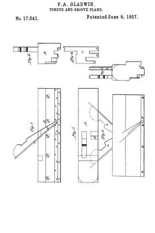
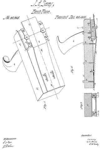
Be it known that I, TIMOTHY O. CALLAHAN, of Boston, in the county of Suffolk and State of Massachusetts, have made an invention of a new and useful Plane for Finishing Board Floors of Halls, Dwellings, Navigable Vessels, &c.; and do hereby declare the following to be a full, clear, and exact description thereof, due reference being had to the accompanying drawing making part of this specification, and in which —

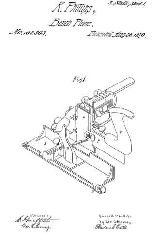
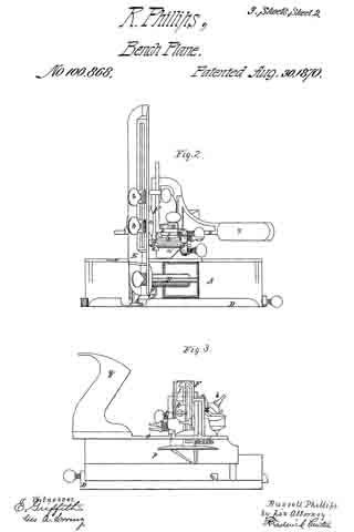
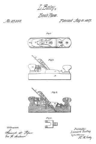
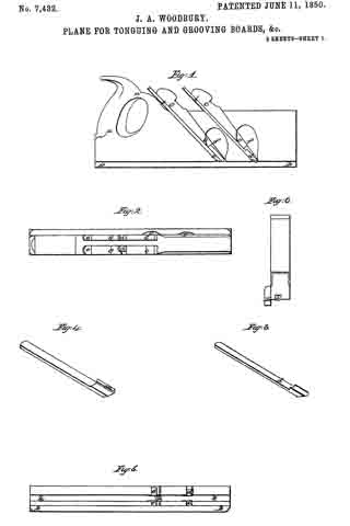
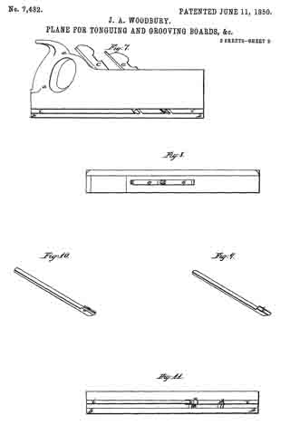
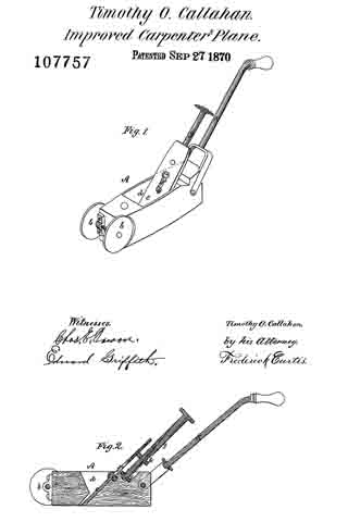
Figure 1 is a perspective view; and
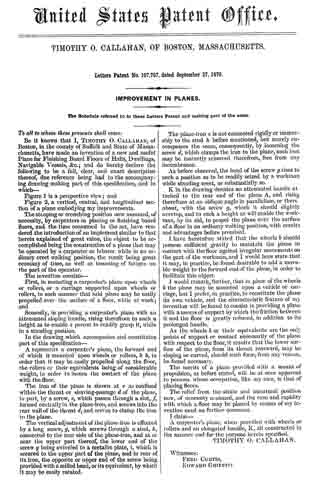
Figure 2, a vertical, central, and longitudinal section of a plane embodying my improvements.

The stooping or crouching position now assumed, of necessity, by carpenters in planing or finishing board floors, and the time consumed in the act, have rendered the introduction of an implement similar to that herein explained of great value, the object to the accomplished being the construction of a plane that may be operated by a carpenter or laborer while in an ordinary erect walking position, the result being great economy of time, as well as lessening of fatigue on the part of the operator.

The invention consists —

First, in mounting a carpenter’s plane upon wheels or rollers, or a carriage supported upon wheels or rollers, in such manner that said plane may be easily propelled over the surface of a floor, while at work; and

Secondly, in providing a carpenter’s plane with an attenuated sloping handle, rising therefrom to such a height as to enable a person to readily grasp it, while in a standing position.

In the drawing which accompanies and constitutes part of this specification —

A represents a carpenter’s plane, the forward end of which is mounted upon wheels or rollers, b b, in order that it may be easily propelled along the floor, the rollers or their equivalents being of considerable weight, in order to insure the contact of the plane with the floor.

The iron of the plane is shown at c as confined within the throat or shaving-passage d of the plane, in part, by a screw, e, which passes through a slot, f formed centrally in the plane-iron, and screws into the rear wall of the throat d, and serves to clamp the iron to the plane.

The vertical adjustment of the plane-iron is effected by a long screw, g, which screws through a stud, h, connected to the rear side of the plane-iron, and at or near the upper part thereof, the lower end of the screw g being swiveled to a metallic plate, i, which is secured to the upper part of the plane, and in rear of its iron, the opposite or upper end of the screw being provided with a milled head, or its equivalent, by which it may be easily rotated.

The plane-iron c is not connected rigidly or immovably to the stud h before mentioned, but merely encompasses the same, consequently, by loosening the screw d, which clamps the iron to the plane, such iron may he instantly removed therefrom, free from any incumberance.

As before observed, the head of the screw g rises to such a position as to be readily seized by a workman while standing erect, or substantially so.

K in the drawing denotes an attenuated handle attached to the rear end of the plane A, and rising therefrom at an oblique angle in parallelism, or there about, with the screw g, which it should slightly overtop, and to such a height as will enable the workman, by its aid, to propel the plane over the surface of a floor in an ordinary walking position, with results and advantages before premised.

l have heretofore stated that the wheels b should possess suflicient gravity to maintain the plane in contact with the floor against irregular movements on the part of the workman, and I would here state that it may, in practice, be found desirable to add a movable weight to the forward end of the plane, in order to facilitate this object.

I would remark, further, that in place of the wheels b the plane may he mounted upon a vehicle or carriage, but I prefer, in practice, to constitute the plane its own vehicle, and the characteristic feature of my invention will be found to consist in providing a plane with a means of support by which the friction between it and the floor is greatly reduced, in addition to its prolonged handle.

As the wheels b or their equivalents are the only points of support or contact necessarily of the plane with respect to the floor, it results that the lower surface of the plane, from its throat rearward, may be sloping or curved, should such form, from any reason, be found necessary.

The merits of a plane provided with a means ol propulsion, as before stated, will be at once apparent to persons whose occupation, like my own, is that of planing floors.

The relief from the strain and unnatural position now, of necessity assumed, and the case and rapidity with which a floor may he planed hy means of my invention need no further comment.

I claim —

A carpenter’s plane, when provided with wheels or rollers and an elongated handle, K, all constructed in the manner and for the purpose herein specified.

TIMOTHY O. CALLAHAN.

Witnesses:
FRED CURTIS,
EDWARD GRIFFITH.

No. 106,868 – Improvement In Carpenters’ Planes (Russell Phillips) (1870)

[paiddownloads id=”171″]106868


UNITED STATES PATENT OFFICE.

_________________

RUSSELL PHILLIPS, OF BOSTON, MASSACHUSETTS.

IMPROVEMENT IN CARPENTERS’ PLANES.

_________________

Specification forming part of Letters Patent No. 106,868, dated August 30, 1870.

_________________

To all whom it may concern:

Be it known that I, RUSSELL PHILLIPS, of Boston, in the county of Suffolk and Commonwealth of Massachusetts, have made an invention of a novel and useful implement which I term a Carpenter’s Combination-Plane; and I do hereby declare the following to be a full, clear, and exact description thereof, due reference being had to the accompanying drawings, making part of this specification, and in which —

Figure 1 is a perspective view; Fig. 2, a plan; Fig. 3, a side elevation; Fig. 4, a vertical section.

This invention combines in one implement elementary features now only found in several independent tools, the result being a great saving in space in transportation, as well as in stores and carpenters’ shops, and enabling a mechanic to obtain, at small comparative cost and in a compact and efficient form, the substitutes for several classes of planes.

I have combined in this instrument a rabbeting-plane and an expansible matching-plane, to operate on and prepare boards of various thicknesses, one side of said rabbeting-plane serving as a fence or guide to the latter, as hereinafter explained.

While this invention consists, primarily, of the combination of a rabbeting-plane and an expansible matching-plane, the latter, in turn, will be found to consist of several members, so organized as to enable one to produce a “tongued groove-connection,” called “matching stuff,” a “cross-channel,” or a “plowed groove of any desired dimensions.”

In the drawings accompanying and illustrating this description of my invention, A denotes a rabbeting-plane, substantially of ordinary construction, with the exception of the removal of the handle, and the erection, at or about its center, of a post or standard, B, which slopes forward at a slight angle, and over the iron ofthe plane, which latter is represented at C. The plane A is further distinguished from others of its class by the addition to its under side of an adjustable gage, D, which converts it into a species of plane called “fillister,” or those in which the width of the rabbet cut by the tool is governed at pleasure.

The standard B supports from its upper part a long horizontal lateral bar or arm, E, departing from it at right angles to the length of the plane, such arm supporting the two movable cutter heads or stocks, which, with their adjuncts, constitute the expansible or variable matching-plane before alluded to, the arrangement of parts, as hereinafter explained, being such that both cutter-heads may be moved together or singly upon the arm and away from the rabbeting-plane A, or toward and away from each other thereupon, the side ofthe rabbeting-plane next adjacent to the said cutter-heads serving, under all circumstances, as a gage or “fence,’ so called, to the matching-plane.

The main or primary cutter-carrier is shown at F in the drawings as composed of a plate or portion, a, sliding upon or against the rear side of the arm E, and connned to such arm, upon which it slides, by clamp-nuts and bolts b b, or their equivalents, the inner end of the said plate a terminating in a right-angular bend or head, c, carrying upon its face the “spur or scoring iron,” such spur-iron a’ being secured in position thereupon by side projections or hooks, e e, and a set-screw, f, as represented, and performing the duties of preparing the way for either one or both of the matching cutters, as the case may be.

Upon the front or inner face of the cutter-carrier F or its cutter-head c, I apply a flat plate or second cutter-head, g, this latter object sliding vertically upon the head c, and being confined thereto by a set-screw or other device. The cutter-head g carries upon its inner face a cutter or iron, h, for cutting or plowing a groove, the relationship of the two cutter-heads being such that the head g may be lowered into a working position, or elevated above the same, while the cutter It may be raised or lowered with respect to its head, according to the depth of cut required, it being understood, as before stated, that when the said cutter (or its companion, to be duly referred to) is at work the side or fence i of the rabbeting-plane A serves as a guide or gage to determine the width of the cut thus made.

The iron or cutter It is composed of an upright flat plate, the lower part of which is bent into an angular sloping portion, which, constitutes its cutting-edge, the cutter by this means saving the necessity of employing two spurs to prepare its way, while the lower edge of the head g serves as a “sword,” so called, to determine the thickness of the shaving cut by the said cutter.

The cutter h, may be employed alone, in connection with the rabbeting-plane, to cut a channel, whether such groove be an ordinary cross-groove or the groove required to receive the tongue of the next adjacent board in “matching stuff,” or the said cutter may be employed in connection with the cutter to cut away one side of the tongue used in said operation of matching stuff; or, again, should occasion require, the cutter or iron h may be lowered and work in conjunction with the rabbeting-plane A, thus cutting at one and the same time a rabbet and groove or channel.

The second cutter, before mentioned, is shown at j in the accompanying drawings as mounted upon the inner face of a second cutter-head, k, which makes part of a carrier, l, mounted and sliding upon the first carrier, F, and confined thereto, by clamp-nuts or set-screws, in any proper manner, it being observed that the construction and relationship of this latter cutter-carrier and head with respect to the former being substantially the same as the former in respect to the arm or support E, before mentioned, it being observed that while the cutter or tool may be moved toward or away from the rabbeting-plane, for the purpose of cutting channels of varying width, the two cutters may be separated or contracted, in order to cut a tongue of any given width up to a certain extent.

Upon the outer or remote side ofthe second cutter-head, k, is disposed an adjustable gage for determining the depth of the cut made by either one or both the cutters h or j, (in connection with the rabbeting-plane as a side gage,) to produce a cross-channel or plow a groove.

As it becomes necessary to produce a sword to regulate the thickness of the shaving cut by the second cutter or iron, j, I form it (the sword) upon the under side of a fiat plate, o, which in turn is suspended from the under side of the carrier l, applied adjustably thereto, and confined in place by set-screws or their equivalents, in order that the lateral position of the said sword with respect to the said cutter j may be varied, as it sometimes becomes desirable that this sword shall travel in the center, or thereabout, of the groove or channel formed by such cutter.

Upon the upper side of the rear extremity of the sword, which is shown at p, or its supporting-plate o, I mount the handle of the combination-instrument, such handle being represented at q in the drawings.

An instrument constructed and organized as above explained may be used as a rabbeting-plane, or fillister simply.

By lowering the cutter h, to the proper extent and employing the side of the rabbeting-plane as a guide or gage, a cross-channel may be cut or a groove may be plowed.

By lowering the second cutter, j , and adjusting the distance between the two to the width of tongue required in machine-stuff, such tongue will be cut to any desired gage, or, as before stated, the second cutter, j, maybe employed alone, in connection with the spur-iron a’, to cut a channel or groove.

For extreme variations in the extent of cuts made by my present invention, I shall adapt cutters of varying widths; but it will be evident that considerable variations maybe made without removing the cutter at the time in use.

In the use of the rabbeting-plane alone, the cutter-head c should be inverted end for end to serve as a gage.

Although I have in the present instance represented one of the cutter-carriers as supported and sliding upon the arm E and the other carrier applied in similar manner to the first, I would remark that I intend applying each carrier by itself to the bed or frame of the tube.

I claim —

The herein-described carpenter’s plane.

RUSSELL PHILLIPS.

Witnesses:
EDW. GRIFFITH,
FRED. CURTIS.

No. 99,137 – Improvement In Joiners’ Planes (George Cyrus Beckwith) (1870)

[paiddownloads id=”162″]99137


United States Patent Office.


GEORGE CYRUS BECKWITH, OF BOSTON, MASSACHUSETTS.

Letters Patent No. 99,137, dated January 25, 1870.
_________________

IMPROVEMENT IN JOINERS’ PLANES.

_________________

The Schedule referred to in these Letters Patent and making part of the same.

_________________

To all whom it may concern:

Be it known that I, GEORGE CYRUS BECKWITH, of Boston, in the county of Suffolk, and State of Massachusetts, have made a new and useful Invention, having reference to Joiners’ Planes; and do hereby declare the same to be fully described in the following specification, and represented in the accompanying drawings, of which —

Figure 1 is a top view;
Figure 2, a side elevation;
Figure 3, an end view; and
Figure 4, a longitudinal section of a joiners’ plane, containing my invention.

This plane has a stock, capable of being expanded and contracted, for the purpose of adapting it to hold plane-irons or cutters, and throat-pieces, of different sizes or widths. lt also has a new and peculiar mechanism for holding the plane-iron or cutter in place in the stock and throat-piece.

The stock is mainly composed of two jaws A B, the handle C being affixed to one of them, viz, that marked A.

Screws a a go through holes made in the jaw B, and screw into projections b b, extended from the jaw A.

Furthermore, a duplex thumb-screw, D, goes through the upper parts of the middles of the two jaws, and over the plane-iron or cutter E, which, with a wooden base-plate or throat-piece, F, is arranged between the two jaws, in manner as represented.

The duplex thumb-screw has two screw-threads c d, which are pitched or run in opposite directions, relatively to one another, one being what is usually termed “a right-hand screw,” and the other “a left-hand screw.”

One of these screws is screwed into the jaw-plate A, and the other into the jaw-plate B, the whole being so that a person, by revolving the duplex screw in one direction, will cause the jaw-plates to recede from one another, and, by turning the said screw in the opposite direction, will cause the two plates or jaws to approach one another. The screws a a serve to compress the jaws upon a throat-piece, when placed between them.

For better supporting a throat-piece by the jaws, I usually make each of the latter with a tongue, f, projecting from its inner side, such tongue being to enter a corresponding groove, g, made in the next adjacent edge of the throat-piece. This throat-piece may have a flat bottom, or it may have a bottom formed like that of any common moulding-plane.

It is intended, by my invention, to have a series of throat-pieces of different widths, and also to have a series of plane-irons or cutters, and cap-irons, to correspond with such, the same being to enable a joiner with one stock, and such a series of throat-pieces and plane-irons, and cap-irons, to compose such a plane as his necessities may require front time to time, whether such be a plane for moulding, or for plane-surface work.

The throat-piece F has a chip-throat, h, made through it, such being to receive the plane-iron or cutter E, and the cap-iron H.

For the support of the plane-iron, the two jaw-plates are provided with rebated ledges, one of which is shown at i, in fig. 4.

Furthermore, a stud, k, extends from the inner face of each jaw-plate, in manner as shown in figs. 1 and 4. These studs serve as bearings or fulcra for the cap-plate, which is passed underneath both of them, and, at its lower part, rests on the plane-iron or cutter.

There is, between the two screws of the thumb-screw D, an arm, l, which turns freely on the shank of the screw, or is pivoted to the screw, so as to be capable of turning up and down thereon.

A cammed lever, L, jointed to the said arm, either bears upon the plane-iron, or upon a spring, n, projected from the rear part of the arm, and resting on the plane-iron.

By pressing down the tail or handle o of the cammed lever L, the arm I will be elevated against the cap-iron, and the cam p of the lever will be forced against the plane-iron, and thus, by means of the iron and the cammed lever, and the supports of the plane-iron and the cap-iron, such plane-iron and cap-iron may be fastened simultaneously in place in the stock and throat-piece.

In the above-described plane, I claim, as my invention, the following, viz:

The stock, as composed of the two jaws A B, and their clamping and expanding dowels or screws a a D, substantially as set forth, in combination with a separate throat-piece, F, as explained.

Also, the combination of the arm Z and the cammed lever L, applied to the duplex extension-screw D, and arranged with the plane-cutter E and the cap~iron H, as explained.

GEORGE CYRUS BECKWITH.

Witnesses :
R. H. EDDY,
S. N. PIPER.

No. 105,869 – Improvement In Carpenters’ Planes (Charles E. Tucker) (1870)

[paiddownloads id=”169″]105869


United States Patent Office.


CHARLES E. TUCKER, OF BOSTON, MASSACHUSETTS, ASSIGNOR TO
HIMSELF AND T. L. APPLETON, OF SAME PLACE.

Letters Patent No. 105,869, dated July 26, 1870
_________________

IMPROVEMENT IN CARPENTERS’ PLANES.

_________________

The Schedule referred to in these Letters Patent and making part of the same.

_________________

To all whom it may concern:

Be it known that I, CHARLES E. TUCKER, of Boston, in the county of Suffolk and State of Massachusetts, have invented certain new and useful Improvements in Carpenters’ Planes; and I do hereby declare that the following is a full and exact description thereof reference being had to the accompanying drawing and to the letters of reference marked thereon.

To enable others skilled in the art to make and use my invention, I will proceed to describe its nature, construction, and use.

The nature of my invention consists in the construction and arrangement of the parts composing my invention, as will he hereinafter fully described and set forth.

Drawing.

Figure 1 represents a perspective view of my invention.
Figure 2 is a plan, showing the under side of the plane.
Figure 3 is a cross-section of the plane.

General Description.

The body of my plane consists, essentially, of two parts, C and C’, each of which parts have a downwardly projecting flange, H and H’; these two flanges together constitute the fence, and, being connected with the parts C C’, are adjustable in relation to each other.

This adjustment is effected by loosening the screws E and E’, fig. 1, which will allow the part C, to which the flange H is attached, to he moved, so that the flange H may be in contact with the flange H’, as shown in fig. 1, or may be at a distance from it, as shown in figs. 2 and 3.

The width of groove to be cut will depend upon the distance that the flanges H and H’ are from each other, and, as the flanges are adjustable, it will be seen that, with this plane, a groove of any width may he cut.

A and A’ are plane-irons attached to the parts B and B’ by set-screws S and S, as shown.

If desirable, a single iron may be used to take the place of the two irons A and A.

When a single iron is used it must be changed for each adjustment of the flanges H and H’, that is, for each width of groove required.

Each part of the plane is provided with a marker, one of which is shown at M, arranged as in an ordinary grooving-plane.

I am aware of the patent granted to T. Duvall, March 23, 1869, and therefore do not claim the features of his device.

Claim.

What I claim as my invention, and desire to secure by Letters Patent of the United States, is —

The parts C C’, flanges H H’, set~screws E E’, parts B B’, and planing-knives A A’, when constructed and arranged substantially as shown and described.

CHARLES E. TUCKER.

Witnesses:
FRANK G. PARKER,
E. A. NICKERSON.

No. 86,741 – Improvement In Box-Scraper (William Dutton) (1869)

[paiddownloads id=”148″]86741


United States Patent Office.


WILLIAM DUTTON, OF BOSTON, MASSACHUSETTS.

Letters Patent No. 86,741, dated February 9, 1869.

_________________

IMPROVEMENT IN BOX-SCRAPER.

_________________

The Schedule referred to in these Letters Patent and making part of the same.

_________________

To all whom it may concern:

Be it known that I, WILLIAM DUTTON, of Boston, in the county of Suffolk, and State of Massachusetts, have invented a new and useful Irnprovernent in Combined Planer and Scraper; and I do hereby declare that the following is a full, clear, and exact description thereof, which will enable those skilled in the art to make and use the same, reference being had to the accompanying drawings, forming part of this specification.

This invention relates to a new and useful improvement in tools used for scraping and planing boxes or barrels, and for removing the marks therefrom; and the invention consists in attaching to a single stock or handle an adjustable scraper, and an adjustable “planing-iron,” as will be hereinafter more fully described.

Figure 1 represents a top view of the tool.
Figure 2 is a longitudinal side view, (in section through the line x x,) so as to show the position and method of fastening and adjusting the scraper and planer-“bits.”

Similar letters of reference indicate corresponding parts.

A is a metallic stock, or shell, so formed that a planing-iron, or bit, is confined to it at about the same angle it would occupy in a joiner’s plane.
B represents the iron, or “bit,” of the plane.
C is the scraper.
D is the shank, to which a handle, of wood or other material, may be attached, or the shank may be extended, so as to form a handle itself.
E is the handle.

Both of the bits, B and C, have slot-holes, so that they can be adjusted or set, for properly operating on the wood.

They are fastened by the thumb-screw F and the screw-lever G, as seen in the drawing.

The manner of operating with the tool will be readily understood from the drawing.
I claim as new, and desire to secure by Letters Patent —

The stock A, adapted to receive the adjustable bits B C, all the parts being constructed and arranged as described, for the purpose specified.

WM. DUTTON.

Witnesses:
ALBERT O. NORTON,
MARTHA A. NORTON.

No. 72,443 – Improvement In Carpenters’ Planes (Leonard Bailey) (1867)

[paiddownloads id=”134″]72443


United States Patent Office.


LEONARD BAILEY, OF BOSTON, MASSACHUSETTS.

Letters Patent No. 72,443, dated December 24, 1867.
_________________

IMPROVEMENT IN CARPENTERS’ PLANES.

_________________

The Schedule referred to in these Letters Patent and making part of the same.

_________________

TO ALL PERSONS TO WHOM THESE PRESENTS SHALL COME:

Be it known that I, LEONARD BAILEY, of Boston, in the county of Suffolk, and State of Massachusetts, have invented a new and useful Improvement in Bench-Planes; and I do hereby declare the same to be fully described in the following specihcation, and represented in the accompanying drawings, of which —

Figure 1 is a top view, and Figure 2, a longitudinal section of a plane-iron and its cap-iron, and their holding-devices, such cap-iron being constructed in accordance with my improvement.

Figure 3 is a longitudinal section of the plane-iron and cap-iron, as ordinarily constructed, that is to say, with one bend, a, only near the bearing-edge of the cap-iron.

My object is to use very thin steel plane-irons, and in so doing I find that they are liable to buckle under the pressure of the cap, which causes them to chatter, and makes them otherwise imperfect; and my invention consists in the providing of an auxiliary point of contact between the cap and plane-iron, and at the point where the plane-iron tends to buckle or rise from its bed or base, and thus have a pressure at that point in addition to that at the cutting-edge, which firmly holds this thin plane-iron to its bed.

The cap-iron, as commonly constructed, that is, as shown at D, in fig. 3, when applied to the plane-iron E, will rest thereon only at the extreme lower end of the cap-iron, and also at or very near its upper end. There will be along angular space, b, between the two irons, when they are clamped together by the holding-devices which are represented in figs. 2 and 3, at A, B, and C, and consist of a screw, A, a bearing, B, and a cam-lever, C, arranged in a manner well known.

The dfficulty experienced from the construction of the cap-iron with the single bend a, is, that it allows of vibration of the cap-iron and the plane-iron while in use, such vibration being productive of what joiners term “chattering,” and consequent defective operation of the plane.

In carrying out my improvement, I make the cap-iron with an additional bend, b, (see figs. 2 and 3,) at a short distance back of its lower end or toe, or at a distance therefrom equal to about double the distance at which such lower edge or toe is to be from the main bend a, or the toe of the bearer B, the same being as shown in figs. 2 and I, so as to cause the cap-iron D’ to bear on the plane-iron E’ in three places, or at the toe and auxiliary bend of the cap-iron, and along from such bend to the heel or upper end of the cap-iron. This construction or formation of the cap-iron D’ completely obviates the difficulty above mentioned, and is a very valuable and useful improvement.

In all bench~planes the plane-iron must project slightly beyond its bed or bearing, the edge of the bed beyond which it projects serving as a fulcrum to the force of the pressure ofthe cap upon the extreme edge of the plane-iron. When thick plane-irons are used, their stiffness may resist the pressure of the cap sufficiently to prevent buckling or rising of the plane-iron from its bed; but in thin steel plane-irons which I use, the pressure of the cap upon the projecting portion of the plane~iron causes this portion to yield slightly, and of course produces buckling at some point behind, and generally close to the fulcrum. To prevent this buckling or rising, and still use the thin steel plane-irons, I put an extra bend in the cap, so that it shall have a point of impact with the thin steel at the place where it tends, from the pressure on its projecting edge, and the fulcrum behind that edge, to risefrom its bed, and thus I effectually prevent “buckling” and “chattering,” whilst I can avail myself of the economy of thin steel for the plane-irons.

What I claim as my invention, and desire to secure by Letters Patent in the adaptation of thin steel to the plane-irons of bench-planes, is —

The auxiliary point of impact between the cap and the thin plane-iron, at the point or portion thereof where the thin steel tends to buckle under the pressure of the cap upon the projecting edge of the plane-iron, substantially in the manner described.

LEONARD BAILEY.

Witnesses:
R. H. EDDY,
F. P. HALE, Jr.

No. 67,398 – Improvement In Bench-Planes (Leonard Bailey) (1867)

[paiddownloads id=”130″]67398


United States Patent Office.


LEONARD BAILEY OF BOSTON, MASSACHUSETTS.

Letters Patent No. 67,398, dated August 6, 1867.
_________________

IMPROVEMENTS IN BENCH-PLANES.

_________________

The Schedule referred to in these Letters Patent and making part of the same.

_________________

TO ALL PERSONS TO WHOM THESE PRESENTS SHALL COME:

Be it known that I, LEONARD BAILEY, of Boston, in the county of Suffolk, and State of Massachusetts, have invented a new and useful Improvement in Joiners’ Planes; and I do hereby declare the same to be fully described in the following specification, and represented in the accompanying drawings, of which —

Figure 1 is a top view.

Figure 2, a side elevation, and

Figure 3 a longitudinal section of a plane provided with my invention.

The stock of the plane I construct in two parts, A B, the throat C for the reception ofthe plane-iron being formed in both of them in manner as represented. The lower portion B of the stock I make of wood, and the upper portion A of iron or metal, each being formed in manner as represented in the drawings. The portion A is placed on the top of the part B, and they are connected by clamp-screws a b going down through slots c d made in the part A, the same being so as to enable the part A to he moved a little lengthwise or adjusted on the part B, as occasion may require, in order to bring the plane-iron supporting-face e of such part A flush or even with the upper surface of a thin plate when glued or fixed to the plane-iron or supporting-face f of the part B. As the lower surface of the part B may become worn away, from use of the plane, the opening of the lower part of the throat will grow wider, and finally become so wide as to render it necessary to glue, or fix on the back or inclined face of that part of the throat which is on the part B, a thin layer or plate of wood or other material of sufficient thickness to bring the plane-iron in its true relation with the front edge of the opening of the throat. The advantage of applying the parts A and B to each other in manner or so as to enable the part A to be moved and adjusted on the part B will thus be apparent. The plane-iron is represented at C’ as provided with a cap-iron, D, which is fastened to the plane-iron by means of a clamp-screw, g, which goes through a slot, k, made lengthwise in the plane-iron and screws into the cap-iron. The cap-iron, near its upper end or heel, and directly over the slot h, I form with a hole or slot, k, to receive the shorter arm l of a forked lever, D’, which, with its fulcrum m, is arranged in the part A in manner as represented. The said forked lever is shown in top view in Figure 4, its shorter arm being arranged at or about at a right angle with its longer or furcated arm. The two prongs of the forked arms embrace the shank of a nut, E, and enter a groove, l’, made in and around the shank. This nut is screwed on a vertical male screw, F, extending up from the part A and near to its rear handle m’, in manner as shown in the drawings. The object of the said nut and furcated lever, as arranged and applied to the part A or the plane-stock, and the cap of the plane-iron, as explained and represented, is to enable a person to move the said plane-iron lengthwise in order to properly adjust its cutting-edge with reference to the bottom surface of the plane-stock. Were the hole k in the plane-iron instead of in the cap-iron, the plane-iron, as it might become worn up by the process of sharpening it, would require a new hole or series of holes in it to render it available, but by having the hole k in the cap-iron, such hole not only serves, with the shorter arm of the lever D, as a means of readily attaining the proper position of the plane-iron and its cap-iron in the stock, but enables the plane-iron to be adjusted by the action of the lever and the nut and screw, and to be adjusted on the cap-iron, as occasion may require, after a sharpening of the plane may have taken place. In order to aid in depressing the heel of the fastening bearer or lever G from the head of the screw H, as well as to afford a means of aiding in throwing up the cam-lever I, and to enable the cam o of such lever to turn without friction on the cap-iron, I affix to the bearer, on its under side, a spring plate, p, it being arranged with the bearer and its lever I in manner as represented.

What I claim as my invention in the above-described joiner’s plane is as follows:

I claim the arrangement of the two parts A B of the stock together, and with slots c d and clamp-screws a b, as described, whereby such parts may be adjusted with reference to each and clamped together as and for the purpose specified.

I also claim the combination as well as the arrangement of the adjusting screw F and nut E, or the equivalent thereof, and the bent lever, with the plane-stock.

Also, the arrangement of the hole k in the cap-iron to operate with the adjusting lever, combined with the screw and nut, or the equivalent thereof, and applied to the stock, as set forth.

LEONARD BAILEY.

Witnesses:
R. H. EDDY,
GEO. H. ANDREWS.

No. 55,599 – Improvement In Spokeshaves (Leonard Bailey) (1866)

[paiddownloads id=”118″]55599


UNITED STATES PATENT OFFICE.

_________________

LEONARD BAILEY, OF BOSTON, MASSACHUSETTS.

IMPROVEMENT IN SPOKESHAVES.

_________________

Specification forming part of Letters Patent No. 55,599, dated June 19, 1866.

_________________

To all whom it may concern:

Be it known that I, LEONARD BAILEY, of Boston, in the county of Suffolk and State of Massachusetts, have invented an Improved Spokeshave; and I do hereby declare the same to be fully described in the following specification, and represented in the accompanying drawings, of which —

Figure 1 denotes a top view, Fig. 2 a front elevation, Fi g. 3 a transverse section, and Fig. 4 a longitudinal section, of it.

In carrying out my invention I construct the stock of the spokeshave in two separate parts. and so that each of its handles shall be divided into two parts length wise, in manner as shown at a a’ in Figs. 1, 2, and 4. The two lowermost parts, a’ a’, of the handles I combine in one piece with the cutter rest or supporter — that is, so as to extend in opposite directions therefrom — and I also combine the other two or upper parts, a a, of the handles with the adjustable shank-piece c, so as to be in one piece therewith and to extend in opposite directions from it, in manner as exhibited in the figures.

The cutter or shave iron d, resting on the part b, I secure thereto by means of a clamp-bar, e, which is arranged on the cutter and directly over the part b, and is held in place (and so as to conbine the cutter to the said part D) by means of two screws, f f, which go through the lower parts of the handles and screw through the said clamp-bar e, each of such screws being arranged at right angles, or thereabout, with the lower or bearing surface of the part b.

Furthermore, the clamp-bar is caused, near its ends, to abut against two shoulders, i i, formed in or on the stock. These shoulders are arranged in front of the clamp-bar, and not only serve to prevent the downward strain of the screws from breaking the said screws, but co-operate with the screws in setting the bar closely against the cutter or shave-iron, so as to confine it firmly to its bed.

The parts a a touch the parts a’ a’ simply at or near their extremities, the same being in order that such parts a a, with the extension portion c, may constitute a bow or curved spring, to raise the said portion relatively to the cutter, and so as to increase the throat of the implement.

The screws f f are to extend through the parts a a, and screw into nuts g g, so applied to them as to act against the said parts a a, the said nuts and screws serving to effect a counter-movement of the part c, for the purpose of disconnecting the throat of the spoke shave.

The arrangement of the screws f f, the shoulders i i, and the clamp-bar e relatively to the cutter or iron d, the bed on which it rests, and the bottom, surface of the part b renders the clamp very efficient in holding the cutter down to the bed, however the clamp, by the action of the screws, is driven downward in a direction which is at an obtuse angle, its surface in contact with the plane-iron. The screws f f, by their arrangeinent, perform the duty not only of holding the clamp down upon the plane iron, but of co-operating with their nuts in springing the upper parts, a a, ot the handle, so as to regulate the distance of the throat-piece c from the plane-iron.

What I claim in the above improved spoke-shave is as follows:

1. The combination of the screws f f and nuts g g, or their equivalents, with the clamp-bar e, and with the stock divided length wise into two parts or portions, constructed substantially in manner and so as to operate as described.

2 The arrangement of the clamp-bar e with the screws f f and nuts g g, and with the stock divided lengthwise into two parts or portions, constructed substantially in manner and so as to operate with the said screws and nuts, substantially as set forth.

3. The combination and arrangement of the shoulders i i with the screws f f, the clamp-bar e, the cutter d, and bed b, or the stock, substantially as set forth.

LEONARD BAILEY.

Witnesses:
R. H. EDDY,
FREDERICK CURTIS.

No. 19,359 – Securing The Plane Iron To Its Stock (P.A. Gladwin) (1858)

[paiddownloads id=”71″]19359


UNITED STATES PATENT OFFICE.

_________________

P. A. GLADWIN, OF BOSTON, MASSACHUSETTS.

METHOD OF SECURING THE PLANE-IRON TO ITS STOCK.

_________________

Specification of Letters Patent No. 19,359, dated February 16, 1858.

_________________

To all whom it may concern:

Be it known that I, P. A. GLADWIN, of Boston, in the county of Suffolk and State of Massachusetts, have invented a new and useful Improvement in Joiners’ Planes; and I do hereby declare that the following is a full, clear, and exact description of the same, reference being had to the annexed drawings, making a part of this specification, in which —

Figure 1, is a longitudinal vertical and central section of my iinproveinent. Fig. 2, is a transverse section of do, taken in the line (x), (x), Fig. 1, and looking in the direction indicated by the arrow. Fig. 3, is a plan or top view of do.

Similar letters of reference indicate corresponding parts in the several figures.

This invention consists in a novel manner of securing the iron in the plane, as hereinafter described, whereby the iron may be readily adjusted in the plane and at the same time firmly secured therein.

To enable those skilled in the art to fully understand and construct my invention I will proceed to describe it.

A, represents the stock of a plane constructed externally in the usual way and provided with an ordinary cutter or “iron” B.

C, is the “throat” of the plane in which the iron B, is placed or fitted and secured. This throat is not provided with the usual grooves at its sides (a) to receive a wooden wedge as ordinary planes, the sides of the throat being perfectly vertical and the space between the sides being equal to the width of the iron B, as shown clearly in Fig. 2. The back (b) of the throat C, has the usual inclination, and its front is of double inclined form as usual and shown at (c) (d) Fig. 1. On the inclined part (c) of the front of the throat C, a plate D, is placed. This plate has an oval opening (e) made in it as shown clearly in Fig. 2, and the lower edge of the plate has a foot piece or projection (f) at each end, the lower surfaces of which are parallel with the outer surface of the cover or cap E, of the iron, see Fig. 1.

F, is a plate on the inner side of which a projecting ledge or bit (g) is formed. This plate is secured to the part (c) of the front side of the throat by a screw (d’) which passes through the oval opening (e) in the plate D, the plate being allowed to turn on said screw and the ledge or bit (g) also fits within this opening as shown clearly in Figs. 1 and 2. The ledge or bit (g) is not at the center of the plate F, but is rather at one side of it, the screw (d’) passing through one end of the ledge or bit (g) as shown clearly in Fig. 2. The plate F, is provided with a thumb piece (h) at its upper end.

In consequence of having the bit (g) placed at one side of the center or screw (d’) and having said bit fitted within the oval opening (e) of the plate D, the plate D, will be raised and lowered turning the plate F, on its screw or center (d and it will be seen that when the plate F, is turned in the direction indicated by arrow (1) the foot pieces or projections (f), (f), will be forced down or against the cap or cover E, of the iron B, and will retain the iron firmly in its place as shown in black in Fig. 1, and in red in Fig. 2. By turning the plate in the opposite direction as indicated by arrow (2) the foot pieces or projections (f), (f) will be raised and the iron may be entirely withdrawn from the stock or adjusted or set as desired and then firmly secured by turning plate F, in the direction indicated by arrow 1.

This invention is extremely simple and allows of the ready adjustment of the iron.
It may be applied to any ordinary plane with the greatest facility, the device being made of varying sizes to suit different sized planes.

Having thus described my invention what I claim as new and desire to secure by Letters Patent, is,

The two plates D, F, constructed as shown, viz., the plate D, being provided with the foot pieces or projections (f), (f), and the oval opening (e), and the plate F, provided with the bit (g) and pivoted to the part (c) of the throat C, so that the bit may work within the oval opening (e) of the plate D, substantially as and for the purpose set forth.

P. A. GLADWIN.

Witnesses:
SAMUEL CALDIROTT,
J. B. CALDIROTT.

No. 14,979 – Method Of Securing Plane Bits (Thomas D. Worrall) (1856)

[paiddownloads id=”33″]13957


UNITED STATES PATENT OFFICE.

_________________

THOMAS D. WORRALL, OF BOSTON, MASSACHUSETTS.

METHOD OF SECURING PLANE-BITS.

_________________

Specification of Letters Patent No. 14,979, dated May 27, 1856.

_________________

To all whom it may concern:

Be it known that I, THOMAS D. WORRALL, of Boston, in the county of Suffolk, and State of Massachusetts, have invented an Improvemnt in Carpenters’ Molding-Planes; and I do hereby declare that the same is fully described and represented in the following specification and the accompanying drawings, of which —

Figure 1, is a top view, and Fig. 2, a side elevation of a plane containing my improvement. Fig. 3, a vertical, central and longitudinal section of it. Fig. 4, a side view of the clamp to be hereinafter described. Fig. 5, a front view of said clamp. Fig. 6, a front view of the plane iron as removed from its stock.

The nature of my invention consists in an improved arrangement of clamping mechanism, or that used for retaining the plane-iron within the throat of its stock. In the said drawings A, denotes the stock; B, the cutter or plane-iron; and C, the throat of the stock.

In order to hold the plane iron within the stock, I employ a clamp or piece of metal, D, made to extend partially around it or embrace it and to be arranged with respect to it as seen in the drawings, the said clamp being placed in a recess a, leading out of the rear and upper part of the throat and made of a suitable size to allow the clamp to be moved backward far enough to draw the plane iron closely against the surface of the throat. A female screw, b, is formed through the rear part of the clamp and so as to receive a male screw, C’, out on the end of a long rod E, which extends longitudinally through the stock A and from its rear end to the clamp and has a shoulder, d, and a flat head or handle, e, as seen in the drawings. By turning the rod so as to cause the screw, C’, to enter the clamp, the said clamp may be drawn down closely upon the plane-iron so as to confine it closely or firmly in the throat of the stock.

By my arrangement of the confining contrivances, the throat of the plane-iron is not obstructed by any device, extending across it transversely, the plane cutter being held in place by the backward draft of the clamp and the bearing of the rod of the shoulder E, against the rear end of the plane stock.

I do not claim merely holding the plane or cutter in place in its throat by a wedge, screw, or equivalent device forced into the throat and across it and against the plane-iron, but

What I do claim is —

The arrangement of the clamp, D, and the screw rod E with respect to the plane cutter and its stock substantially as described.

In testimony whereof, I have hereunto set my signature this twenty-seventh day of February A. D. 1856.

THOS. D. WORRALL

Witnesses:
R. H. EDDY,
F. P. HALE, Jr.

No. 7,432 – Plane For Tonguing And Grooving Boards (James A. Woodbury) (1850)

[paiddownloads id=”4″]7432


UNITED STATES PATENT OFFICE.

_________________

JAMES A. WOODBURY, OF BOSTON, MASSACHUSETTS.

PLANE FOR TONGUING AND GROOVING BOARDS, &c.

_________________

Specification of Letters Patent No. 7,432, dated June 11, 1850.

_________________

To all whom it may concern:

Be it known that I, JAMES A. WOODBURY, of Boston, in the county of Suffolk and State of Massachusetts, have invented certain new and useful Improvements in Apparatus for Tonguing and Grooving Boards, Planks, &c., and that the following description, taken in connection with the accompanying drawings hereinafter referred to, forms a full and exact specification of the same, wherein I have set forth the nature and principles of my said improvements by which my invention may be distinguished from others of a similar class together with such parts as I claim and desire to have secured to me by Letters Patent.

The figures of the accompanying plate of drawings represent my improvements.

Figure 1 is a side elevation of hand plane arranged with my improvements for cutting, or forming tongues in boards or planks. Fig. 2 is a top view of the same.

Fig. 3 is an isometrical perspective view of a gouge used in said plane, and Fig. 4 is a similar view of a smoothing chisel set behind this gouge in said plane; and Fig. 5 is a plan of the underside of said plane, and Fig. 6 is an end view of the same. Precisely similar views of a hand plane for forming grooves in boards or planks, to those represented in Figs. 1, 2, 3, 4, 5 and 6, are shown respectively in Figs. 7, 8, 9, 10, 11 and 12.

As the implements for forming tongues and grooves are now arranged, there is but a single cutting chisel of the ordinary shape or construction, the edge of which penetrates into the wood, and tears out the shaving from the sides of the groove or tongue, and leaves said sides rough and imperfect. While in cross-grained lumber and wet wood it is almost impossible to form a tongue or groove with the tools now in common use.

The defective operation of the tools heretofore devised, in the particular above noted, has long been sought to be remedied, and by my improvements the difliculties and imperfections above referred to are entirely obviated.

In my improved apparatus I use two cutting tools or chisels. That which first enters the wood is a gouge-cutter with a semi-circular cutting edge, which operates to take out the greater portion of the shaving required to be removed from the groove, or on each side of the tongue. And behind this gouge cutter is set a smoothing cutter havlng a common chisel edge at the bottom, and on each side thereof a cutting or face, the chisel edge operating to smooth the bottom of the groove &c., and the cutting lips serving to smooth the sides of the grooves and tongues.

The two hand planes shown in the drawings, are constructed in most respects, in the plane stocks, like those in common use for forming tongues and grooves. The handles of both stocks are shown at a a–a a, Figs. 1 and 7, and the guiding ledges which fit against the face of the boards or planks, are shown at b b–b b, in said figures, and in Figs. 5, 6, 11 and 12. They are both also contrived in the usual way, with the wooden wedges, c c c &c., Figs. 1 and 2, 7 and 8, for confining the cutting tools in proper position. The plane for forming the tongue has two sets or series of gouges and smoothing chisels, above referred to, as shown at d, e–d, e, Figs. 1, 2 and 5, and two throats, f f–g g, on each side for the delivery or escape of the shavings, as shown in said Figs. 1 and 2. It also has the usual groove, h h, Figs. 5 and 6, on its under side, which fits, and plays over the tongue as it is made.

The grooving plane requires discharging throats but on one side, and has the usual tongue, i i, Figs. 7, 11 and 12, along its under side through which the cutting tools pass, and which fits into, and plays through the groove, as it is made deeper and deeper in the board or plank.

As before suggested, and explained, the main feature of my invention consists in the use of gouges, d–d, in the tonguing plane, and k, in the grooving plane, to precede a smoothing tool, e–e and l, in said tonguing and grooving planes respectively; the said smoothing tools having lips to cut smoothly on the sides of the grooves and tongues to be formed. The gouges, d–d and k, have semi-circular cutting edges, and should be so set in the plane stocks, see Figs. 1 and 5, 7 and 11, as that the corners should penetrate into, and engage with the wood first, so as to turn the shavings up into the discharging throats freely. The smoothing irons in the tonguing plane have but one smoothing lip or face, as shown at m, Figs. 4 and 5, there being two such tools the front or cutting edge of the lip of one of which cuts on each side of the tongue, while the grooving plane has but one such tool, with a lip, n–n, on each side, the front or cutting edge of which serves to smooth each side of the groove. The smoothing tools which are set behind the gouges in both plane-stocks, shown in the drawings, should, like the gouges, to be so fixed in position, as the upper corners of the front or cutting edges of the side lips, m–n, n, shall first engage with, and penetrate the wood, as, by thus arranging them a “drawing stroke,” (so to speak,) is produced, as the planes are moved along, and the shavings, as before suggested, are more freely discharged through the throats formed in the stocks for the purpose.

It will be evident to any mechanic versed in the arts of carpentry or joinery, that the arrangement of tools for forming tongues and grooves hereinabove suggested, and described, may be used in stationary positions in a manner which will be readily understood, on the sides of power planing machines; or a series of alternate gouges smoothing cutters constructed as above described, may be set in a revolving frame or stock, and produce a much improved result on that which is now effected in such machines. A sufficient number of alternate gouges and smoothing cutters, should be used to out the tongue or groove of any required depth, by passing the board or plank once through the machine. The great end attained by any of the arrangements above described being the removal first by the gouges of the larger portion of the shaving, and then smoothing the sides and bottom of the grooves and sides faces of the tongues and the sunken or rebated edges adjacent to the same, by the smoothing tool, having the lips as described.

Having thus described my improvements, in tonguing and grooving apparatus, I shall state my claim as follows:

What I claim as my invention, and desire to have secured to me by Letters Patent in said apparatus, is —

The combination of a gouge or gouges, (for removing the bulk or greater portion of a shaving in forming tongues or grooves in boards or planks,) with smoothing tools having a chisel edge, a cutting and side lip on either or both sides thereof, (for smoothing the sides and bottom of the grooves, and the edges about the tongues, as set forth) ; said gouges being set in front of said smoothing tools, and the whole being arranged, and operating substantially, as hereinabove set forth.

Boston March 13th 1850.
JAMES A. WOODBURY.

Witnesses:
EZRA LINCOLN,
ROBERT L. HARRIS.

No. 17,541 – Tonguing And Grooving Hand Plane (Porter A. Gladwin) (1857)

[paiddownloads id=”43″]17541


UNITED STATES PATENT OFFICE.

_________________

PORTER A. GLADWIN, OF BOSTON, MASSACHUSETTS, ASSIGNOR TO HIMSELF AND THOS. F.
CALDICOTT.

TONGUING AND GROOVING HAND-PLANE.

_________________

Specification of Letters Patent No. 17,541, dated June 9, 1857.

_________________

To all whom it may concern:

Be it known that I, PORTER A. GLADWIN, of Boston, in the county of Suffolk and State of Massachusetts, have invented an Improved Tongue and Groove Plane or “Match-Plane,” as usually termed; and I do hereby declare that the same is fully described and represented in the following specification and the accompanying drawings, of which —

Figure 1, is a side elevation of my improved plane. Fig. 2, a front end view of it. Fig. 3, a top view of it. Fig. 4, a front view of its plane iron or cutter. Fig. 5, is an end view, and Fig. G, a, side view of the ordinary match plane.

The common match plane is made with two separate throats for the reception of separate cutters, which are arranged so as to stand or slant in opposite directions as shown at a, and b, in Fig. 6.

In Fig. 5 c, and d, represent the vertical guides of the tonguing and grooving cutters, their lower edges being arranged on a level with each other while both of such guides are placed between the tonguing and grooving cutters. After the plane has been used to form a tongue it must be turned around or reversed in the hand in order to enable it to make a groove. This is not the case with my improved match plane which always works in one direction whether it be used for cutting a tongue or for making a groove.

In Figs. 1, 2, and 3, A, denotes the stock or body of the plane, which is constructed with a single throat, B, for the reception of a cutter, or plane iron C, formed as shown in front view in Fig. 4, that is, with a grooving cutting edge, i, and tonguing cutting edges, k, k, arranged with respect to one another as shown in said figure. This cutter, C, stands or slants in one direction and operates with vertical guides c’, d’, and horizontal guides f’, g’, h’, arranged as shown in Figs. 1 and 2.

In the common match plane, the vertical guides, c, d, (see Fig. 5) are arranged below the horizontal guides, and so that their lower edges may be on a level, whereas in my improved plane, the vertical guides, c’, d’, are arranged so that one of them viz d’ extends below the other, while the horizontal guide, f’, of the tonguing cutter is arranged between the said two guides, c’, d’. This latter arrangement enables the plane to be used with one handle and either for tonguing or grooving, while its handle is grasped by the hand of a workman, it not being necessary to reverse the plane during the performance of those operations.

The advantages of the improved match plane will be apparent.

I do not claim the combination of tonguing and grooving cutters, upright and horizontal guides in one stock, wherein the tonguing and grooving cutters are arranged to slant in opposite directions, but

What I do claim as an improvement in the match plane is,

The tonguing and grooving cutter or cutters in a single throat and to slant in one direction in combination with arranging the vertical guides so that one shall stand below the other, and the horizontal tongue guide be arranged between as specified.
In testimony whereof I have hereunto set my signature.

PORTER A. GLADWIN.

Witnesses:
R. H. EDDY,
F. P. HALE, Jr.

No. 98,305 – Whalebone Shaving Plane (James A. Sevey) (1869)

[paiddownloads id=”53″]98305


UNITED STATES PATENT OFFICE.


JAMES A. SEVEY, OF BOSTON, MASSACHUSETTS.

Letters Patent No. 98,305, dated December 28, 1869.
_________________

IMPROVEMENT IN PLANE FOR SHAVING WHALEBONE.

_________________

The Schedule referred to in these Letters Patent and making part of the same.

_________________

To all persons to whom these presents may come:

Be it known that I, JAMES A. SEVEY, of Boston, in the county of Suffolk, and State of Massachusetts, have invented a new and useful or Improved Machine or Implement for Stripping or Shaving Whalebone ; and I do hereby declare the same to be fully described in the following specification, and represented in the accompanying drawings, of which —

Figure 1 denotes a perspective view of it :
Figure 2, a verticle and longitudinal section ; and
Figure 3, a transverse section of it.

In such drawings —

E denotes a plane-stock, made of wood, or other proper material, and provided with a handle, a, which extends from it in manner as exibited in figs. 1 and 2.

At or near its heel, the said stock is rebated entirely across it, as shown at b c d, in fig. 2, and also in fig. 1.

Within the recess or rebate, I arrange, at suitable distances apart, and parallel to each other, two metallic blocks or plane-iron supporters A A, they being rebated on their inner edges, as shown at e e, in fig. 3, in order to receive and support a plane-iron or cutter, C, the bevel f of whose cutting-edge, is arranged upward, or in a manner as shown in fig. 2.

The plane-iron C is held to these supporters A A by means of clamp-screws g g, screwed into the supporters, and arranged, with reference to the plane-iron, in manner as represented.

Each supporter is held in place by three screws, S S P, two of which go through the supporter and screw into the plane-stock. The third screw, P, is arranged between the screws S S, and is screwed through the plane-stock, and against the supporter, the whole being as shown in fig. 2.

By means of these adjusting-screws S S P, the inclination or bevel of the knife or plane-iron can be so adjusted as to bring the cutting-edge thereof down to a plane, L L, which extends from the lower edge of the front end of a plate-spring, M, to the lower edges of the four screws g g.

In advance of the plane-iron C there is a spring-plate or throat-piece M, which is secured to the plane-stock E by means of two screws, B B, which go through slots h h, (made in the plate M,) and screw into the stock.

Furthermore, certain adjusting-screws, D D D, screw down through the stock E, and against the upper surface of the plate M. These screws, with the screws BB, and the slots h h, are to adjust the elastic throat-piece M, or enable it to be perfectly adjusted with reference to the cutting-edge of the plane-iron C.

The implement is to be used in the manner of a common carpenter’s plane, the spring-plate M being first properly adjusted, with reference to the cutting-edge of the plane-iron, so as to cause such edge, when forced against the end of a slab of whalebone, to strike it at the requisite depth.

As soon as the plane-iron enters the slab, the incline f will raise the shaving or part to be split, or force it up from the part below it, so as to split it therefrom.

The spring-plate or throat-piece, operating in conjunction with the knife-edge of the plane f, will not only yield, so as to allow the plane-iron to hit the end of the lab at the proper depth, but will afterward press upon the upper surface of the portion to be removed, and hold the whole down to the bench.

The implement, on being moved forward, will separate a strip of even thickness from the slab, however irregular the slab may be on its upper surface.

I am aware of the plane described in the United States patent, No. 50,947, dated November 14, 1865, and granted to Harrison Ogborn, and I make no claim thereto. My plane differs from it, in having its cutter C sustained by two adjustable supporters A A, which answer not only as means of holding the cutter, but as guides for the shaving, to direct it properly through and out the plane.

My plane also has the elastic throat-piece M. provided with adjustments, by which it can be adjusted both laterally and longitudinally, with respect to the edge of the plane-iron C ; whereas, the throat-piece of Ogborn’s plane is inelastic, and adjustable only laterally, or up and down.

The elastic or spring throat-piece M does not project over the plane-iron, but is arranged in front of it, and with its working end in the same plane with the cutting-edge of the knife C.

In order for the knife C to cut, the throat-piece M must first spring upward, and, while the shaving is being cut, the throat-piece is borne down on it by the inherent elastic force of the throat-piece, the same enabling very thin, and smooth, and even shavings to be removed from the whalebone. Consequently,

What I claim as my invention is as follows :

The combination and arrangement of the spring or elastic throat-piece M, (provided with adjusting-devices, as described,) with the plane-stock E, and the cutter or plane-iron C.

Also, the combination and arrangement of the plane-iron supporters A A, and the clamp-screws g, and adjusting-screws S S P, with the plane-stock E, the cutter C, and the mouth-piece M, provided with devices for adjusting it, as set forth.

J. A. SEVEY.

Witnesses:
R. H. EDDY,
F. P. HALE, Jr.